Horizon Hobby Hangar 9 ultra stick pnp User manual

Ultra Stick™PNP
Instruction Manual
Bedienungsanleitung
Manuel d’utilisation
Manuale di Istruzioni

2EN
NOTICE
All instructions, warranties and other collateral documents are subject to change at the sole discretion of Horizon
Hobby, LLC. For up-to-date product literature, visit horizonhobby.com or towerhobbies.com and click on the support
or resources tab for this product.
Age Recommendation: Not For Children Under 14 Years. This Is Not A Toy.
SAFETY WARNINGS AND PRECAUTIONS
Read and follow all instructions and safety precautions before use. Improper use can result in fire, serious injury and
damage to property.
Components
Use only with compatible components. Should any compatibility questions exist, please refer to the product
instructions, component instructions or contact the appropriate Horizon Hobby office.
Flight
Fly only in open areas to ensure safety. It is recommended flying be done at radio control flying fields. Consult local
ordinances before choosing a flying location.
Propeller
Always keep loose items that can become entangled in the propeller away from the prop. This includes loose clothing
or other objects such as pencils and screwdrivers. Keep your hands away from the propeller as injury can occur.
Batteries
Always follow the manufacturer’s instructions when using and disposing of any batteries. Mishandling of Li-Po
batteries can result in fire causing serious injury and damage.
Small Parts
This kit includes small parts and should not be left unattended near children as choking and serious injury could result.
MEANING OF SPECIAL LANGUAGE
The following terms are used throughout the product literature to indicate various levels of potential harm when
operating this product:
WARNING: Procedures, which if not properly followed, create the probability of property damage, collateral damage,
and serious injury OR create a high probability of superficial injury.
CAUTION: Procedures, which if not properly followed, create the probability of physical property damage AND a
possibility of serious injury.
NOTICE: Procedures, which if not properly followed, create a possibility of physical property damage AND a little or
no possibility of injury.
WARNING: Read the ENTIRE instruction manual to become familiar with the features of the product before
operating. Failure to operate the product correctly can result in damage to the product, personal property and
cause serious injury.
This is a sophisticated hobby product. It must be operated with caution and common sense and requires some basic
mechanical ability. Failure to operate this Product in a safe and responsible manner could result in injury or damage
to the product or other property. This product is not intended for use by children without direct adult supervision. Do
not attempt disassembly, use with incompatible components or augment product in any way without the approval
of Horizon Hobby, LLC. This manual contains instructions for safety, operation and maintenance. It is essential to
read and follow all the instructions and warnings in the manual, prior to assembly, setup or use, in order to operate
correctly and avoid damage or serious injury.
SAFE OPERATING RECOMMENDATIONS
• Inspect your model before every flight to ensure it is airworthy.
• Be aware of any other radio frequency user who may present an interference problem.
• Always be courteous and respectful of other users in your selected flight area.
• Choose an area clear of obstacles and large enough to safely accomodate your flying activity.
• Make sure this area is clear of friends and spectators prior to launching your aircraft.
• Be aware of other activities in the vicinity of your flight path that could cause potential conflict.
• Carefully plan your flight path prior to launch.
• Abide by any and all established AMA National Model Aircraft Safety Code.
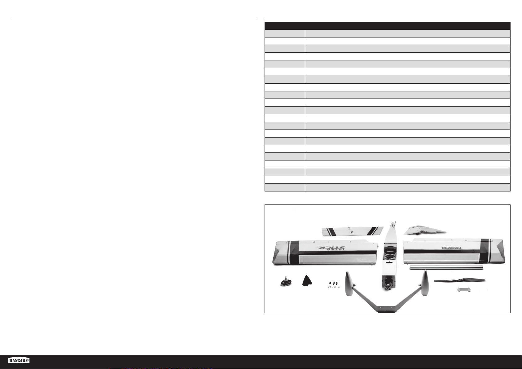
BEFORE STARTING ASSEMBLY
• Remove parts from bag.
• Inspect fuselage, wing panels, rudder and stabilizer for damage.
• If you find damaged or missing parts, contact your place of purchase.
• Charge transmitter and receiver batteries.
• Center trims and sticks on your transmitter.
• For a computer radio, create a model memory for this particular model.
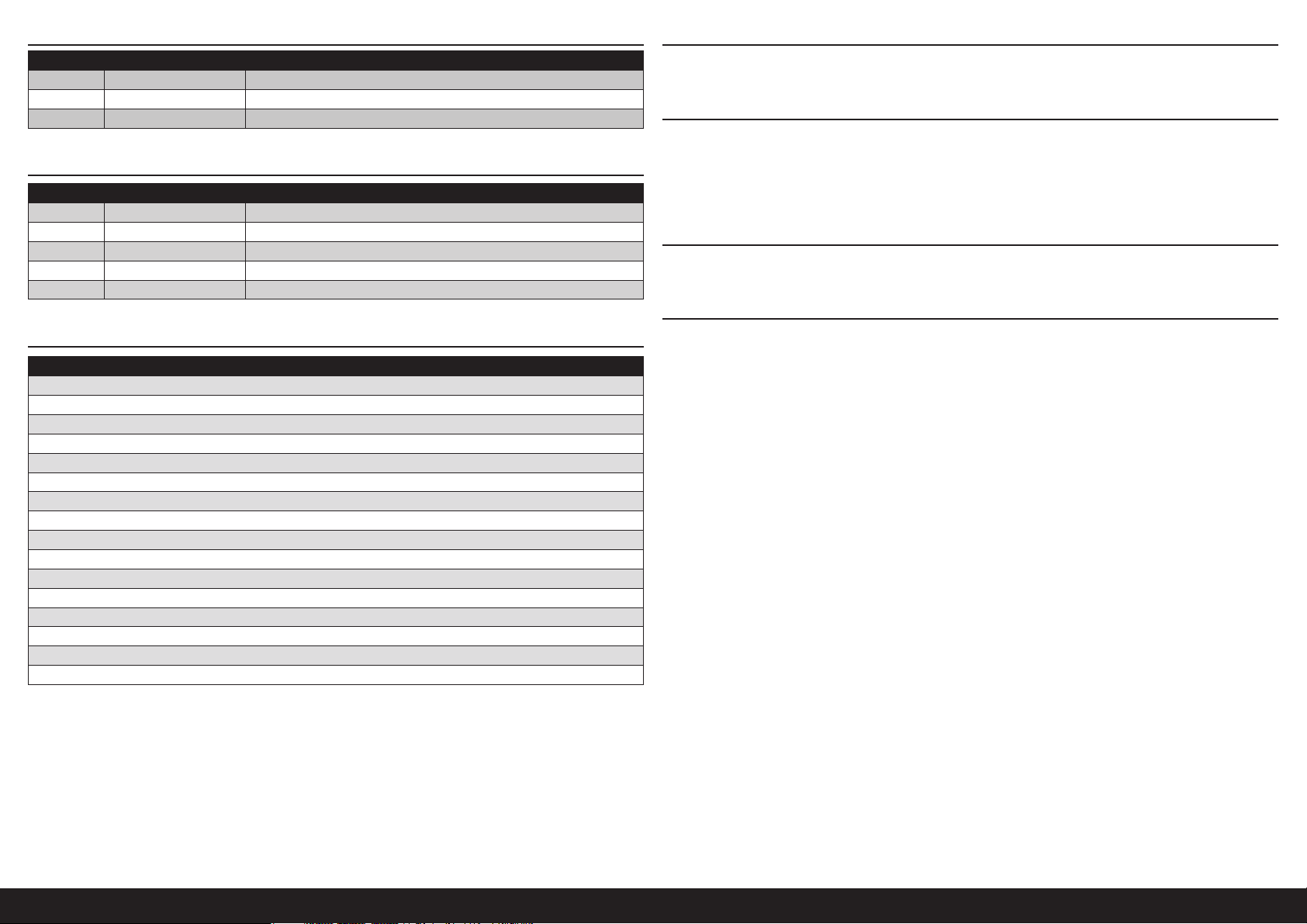
• Bind your transmitter and receiver, using your radio system’s instructions.
NOTICE: Rebind the radio system once all control throws are set. This will keep the servos from moving to their
endpoints until the transmitter and receiver connect. It will also guarantee the servo reversal settings are saved in the
radio system.
FAA INFORMATION
If you own this product, you may be required to register with the FAA.
For up-to-date information on how to register with the FAA, please visit https://registermyuas.faa.gov/.
For additional assistance on regulations and guidance on UAS usage, visit knowbeforeyoufly.org/.

3 EN
Ultra Stick PNP
Part # Description
APC13080E Electric Propeller, 13 x 8E
EFLM7450 BL50 BL Outrunner Motor, 525Kv
EFLR7145 26g Digital MG Mini Servo
HAN234506 Landing Gear
HAN234507 Wheel Pants
HAN234512 Decal Set
HAN234514 Wheels
HAN234517 Tailwheel Assembly
HAN477501 Fuselage
HAN477502 Wing Set
HAN477503 Fin and Rudder
HAN477504 Horizontal Stabilizer
HAN477505 Wing Tube
HAN477508 Aileron & Flap; Right-Hand
HAN477509 Aileron & Flap; Left-Hand
HAN477510 Aileron Set
HAN477511 Hardware Set
HAN477513 Hatch
HAN477515 Battery Tray
HAN477516 Pushrod Set
SPMXAE1060 Avian 60Amp Brushless Smart ESC 6S
REPLACEMENT PARTS
TABLE OF CONTENTS
Replacement Parts........................................................................................................................................................3
Required for Completion ...............................................................................................................................................4
Optional Parts...............................................................................................................................................................4
Required Tools and Adhesives.......................................................................................................................................4
Building Precautions.....................................................................................................................................................4
Removing Wrinkles .......................................................................................................................................................4
Optional Float Installation..............................................................................................................................................4
Transportation and Storage...........................................................................................................................................4
Receiver Installation......................................................................................................................................................5
Rudder and Elevator Installation....................................................................................................................................5
Landing Gear Installation ..............................................................................................................................................6
Elevator and Rudder linkage Connections .....................................................................................................................7
Wing Installation ...........................................................................................................................................................7
Motor Battery and Propeller Installation ........................................................................................................................8
Center of Gravity...........................................................................................................................................................9
Control Throws ...........................................................................................................................................................10
Aerobatic Mixing.........................................................................................................................................................10
Preflight Checklist.......................................................................................................................................................10
Daily Flight Checks .....................................................................................................................................................11
Limited Warranty ........................................................................................................................................................11
Warranty and Service Contact Information ..................................................................................................................12
Academy of Model Aeronautics National Model Aircraft Safety Code............................................................................12

4EN
REQUIRED FOR COMPLETION
# Required Part # Description
1 SPMAR637T AR637T 6CH SAFE and AS3X TelemRx
1 SPMX46S50 4000mAh 6S 22.2V Smart G2 50C
1 SPMX56S30 5000mAh 6S 22.2V Smart G2 30C
REQUIRED TOOLS AND ADHESIVES
Description
Balancing stand
7/8-inch box wrench or socket
Felt-tipped pen
Hemostats
Hex wrench set: Metric
Hobby knife with #11 blade
Hook and loop tape
Low-tack tape
Needle nose pliers
Nut driver set: Metric
Paper towels
Phillips screwdriver: #1, #2
Ruler
Tapered reamer
Tie wraps
Threadlock (blue)
BUILDING PRECAUTIONS
During assembly, we recommend resting the parts on a soft surface such as a soft towel to help prevent denting the
sheeting.
REMOVING WRINKLES
The covering of your model may develop wrinkles during shipping and will require the use of a heat gun (HAN100)
and covering glove (HAN150) or covering iron (HAN101) with a sealing iron sock (HAN141) to remove them. Use
caution while working around areas where the colors overlap to prevent separating the colors. Avoid using too much
heat, which could separate the colors. Placing a cool damp cloth on adjacent colors will also help in preventing the
separation of the colors while removing wrinkles.
OPTIONAL FLOAT INSTALLATION
The Ultra Stick PNP fuselage has been prepared for float installation. For additional details, we recommend
downloading the Ultra Stick 10cc manual (HAN2345).
TRANSPORTATION AND STORAGE
Use the three-view drawing at the back of the manual to determine how much room will be required to transport
and store your model. We also recommend the use of wing bags to help protect these surfaces during transport and
storage. The control horns and linkages can cause damage to other surfaces even when placed in storage bags.
Always transport and store the wings so the linkages do not contact other panels to prevent damage.
# Required Part # Description
SPMAR8360T AR8360T 8CH SAFE Telemetry RX
1 SPMR6775 NX6 6 Ch Transmitter Only
1 SPMR8200 NX8 8 Ch DSMX Transmitter Only
1 SPMX40006S30 4000mAh 6S 22.2V Smart 30C; IC5
1 SPMX50006S30 5000mAh 6S 22.2V Smart 30C; IC5
OPTIONAL PARTS

5 EN
Ultra Stick PNP
2. Slide the wheel collar and bracket down and away from the
bottom of the fin.
RUDDER AND ELEVATOR INSTALLATION
1. Remove the 3mm nut from the fin mounting post. Use a
1.5mm hex wrench to loosen the setscrew that secures the
wheel collar on the tail gear wire.
3. Fit the fin into position in the fuselage.
4. Slide the elevator on the fin mounting posts.
5. Fit the tail wheel bracket over the rear fin mounting post.
Thread an M3 locknut on the mounting post.
RECEIVER INSTALLATION
1. Make the connections from the rudder and elevator servos
to the receiver. Also connect the extensions for the flaps and
ailerons.
All servo extensions have been provided when
using an eight channel radio. No Y-harnesses will be
required. Mixing at the transmitter will be required.
When using a six channel radio, a Y-harness has
been included for the flaps. Mixing at the transmitter
will be required to operate the ailerons.
Using a five channel radio will require the use of the
included Y-harness for the flaps, and an additional
Y-harness (SPMA3058) for the ailerons.
2. Secure the receiver in the fuselage. Use the instructions
included with the receiver for additional mounting details.
Make sure none of the wires from the receiver interfere with
the operation of the servos.
3. Check that the servo arms for the elevator (1) and rudder (2)
are at 90-degrees to the pushrods. Adjust the sub-trim of the
radio or reposition the servo arms as necessary.
4. Label the extensions for the ailerons and flaps.

6EN
7. Place the thin M3 washer on the forward fin mounting post.
Thread an M3 locknut on the fin mounting post. Use a 5.5mm
hex wrench to tighten both M3 locknuts. Make sure no to
over-tighten the nuts, which could damage the stabilizer, fin,
or fuselage.
6. Use a #2 Phillips screwdriver to install the M3 x 10 self-
tapping screw through the hole in the bracket and into the
fuselage. Do not over-tighten the screw and damage the
fuselage.
8. Slide the wheel collar against the bracket, then tighten the
setscrew using a 1.5mm hex wrench.
It is recommended to place a drop of threadlock
on the setscrew to keep it from vibrating loose.
It is not essential to use threadlock if the model
will be disassembled for transport.
LANDING GEAR INSTALLATION
1. Slide an M4 washer on the M4 x 20 socket head cap screw.
Place a drop of threadlock on the screw. Prepare all three
screws.
It is not essential to use threadlock if the model
will be disassembled for transport.
2. Use the screws to attach the landing gear to the bottom of the
fuselage. Use a 3mm hex wrench to tighten the screws. Do
not over-tighten the screws and damage the fuselage.
3. The completed landing gear will look like the photo, with the
wheel pants facing as shown.

7 EN
Ultra Stick PNP
ELEVATOR AND RUDDER LINKAGE CONNECTIONS
1. Remove the 2mm nut from the elevator ball link. Thread the
screw Use a 1.5mm hex wrench to thread the screw through
the center hold of the elevator control horn.
2. With the radio on and the elevator stick and trim centered,
use a ruler to check that the elevator is aligned with the
stabilizer.
3. If the elevator and stabilizer are not aligned, thread the ball on
the elevator in or out to correct the alignment. Make sure to
thread the ball end at the control horn and servo arm equally
as not to damage the ball ends.
4. Once the elevator and stabilizer are aligned, use a 1.5mm hex
wrench to tighten the screw while holding the 2mm locknut
with hemostats or needle nose pliers.
5. Repeat the steps for the elevator to attach the rudder pushrod
and ball end to the rudder control horn.
WING INSTALLATION
1. Connect the leads from the flap and aileron extensions to
the leads from the wing. Mark each lead so they can be
reconnected in the same positions.
2. With the radio on and the aileron stick and trim centered,
check that the aileron is aligned with the wing tip. Adjust the
linkage as necessary to correct the alignment.
3. With the radio on and the flap switch centered, check that
the flap is aligned with the aileron. Adjust the linkage as
necessary to correct the alignment.
4. Slide the wing tube into the wing tube socket.
The wing tube may be a tight fit in the socket.
Polishing the wing tube with fine sandpaper or
steel wool will help ease the installation of the wing
tube. Do not force the wing tube in the sockets as
it can damage the structure inside the wing.
5. Slide the wing panels together. They will fit tightly together
when in the correct position.

8EN
6. Connect the leads for the flaps and ailerons.
Make sure the extensions will not interfere with the
operation of the rudder and elevator servos.
7. Fit the dowels on the leading edge of the wing into the holes
in the fuselage. Make sure the leads for the flaps and ailerons
are inside the fuselage.
8. Place the wing bolt plate on the wing, then thread the 1/4-20
x 13/4-inch nylon wing bolts into the blind nuts in the fuselage
to secure the wing.
Finger-tighten the wing bolts. Over-tightening the wing
bolts can damage the wing structure or wing bolt plate.
MOTOR BATTERY AND PROPELLER INSTALLATION
1. The photo shows the order of the items as installed on the
motor.
Use caution around the motor once the propeller
has been installed. The propeller can cause injury if
the motor starts when the battery is connected.
3. Fit the propeller on the adapter. Thread the propeller nut on
the adapter and tighten the nut using a 7/8-inch socket or
box end wrench.
Do not use pliers to tighten the nut, as they
will damage the aluminum nut over time.
2. Slide the propeller adapter, propeller drive washer and
spinner backplate on the motor shaft.
4. Fit the spinner cone in position. Position the spinner cone so it
does not contact the propeller, Secure the spinner cone using
the provided screw and 1.5mm hex wrench.
5. Secure the motor battery in the fuselage using the hook and
loop straps.
Use hook and loop tape (not included) between
the battery and battery tray to secure the
battery during more aggressive flying.

9 EN
Ultra Stick PNP
CENTER OF GRAVITY
An important part of preparing the aircraft for flight is properly balancing the model.
1. Attach the wing panels to the fuselage. Make sure to connect the leads from the aileron to the appropriate leads
from the receiver. Make sure the leads are not exposed outside the fuselage before tightening the wing bolts. Your
model should be flight-ready before balancing.
2. The recommended Center of Gravity (CG) location for your model is 4 inches (102mm) behind the leading edge of
the wing.
3. When balancing your model, make sure it is assembled and ready for flight. Support the plane upright at the
marks made on the wing with your fingers or a commercially available balancing stand.
The suggested Center of Gravity (CG) is the recommended balance point for first flights. This provides a safe and stable
setting so you may comfortably explore the performance and handling of your model.
The CG Range of 33/4inches to 41/4inches (95mm to 108mm) is the extremes of balance to which the model was flight
tested, and found to be flyable. The stability and performance of the model will vary when adjusted within this range.
As each pilot’s flying style and preferences are different, we suggest that you make small adjustments to the CG until
you find the feel that you prefer.
CAUTION: You must adjust your aircraft’s center of gravity
and balance your model properly before attempting flights.
4 inches
(102mm)
6. The battery cover is held in position using magnets and is not
a structural part of the airframe.
An thumb screw and M3 lock washer have been provided
to secure the cover when performing aggressive maneuvers
that may cause the cover to come loose. Lightly finger-
tighten the screw so it doesn’t vibrate loose in flight.
DECAL INSTALLATION
1. Apply the decals to your model using the photos located
in this section of the manual and the box art from your
model. Use a spray bottle and a drop of dish washing liquid
or glass cleaner sprayed in the location of the decal to
allow repositioning of the decal. Use a paper towel as a
squeegee to remove excess water from under the decal.
Allow the model to rest overnight so the remaining water can
evaporate.

10EN
CONTROL THROWS
1. Turn on the transmitter and receiver of your model. Check the movement of the rudder using the transmitter.
When the stick is moved to the right, the rudder should also move right. Reverse the direction of the servo at the
transmitter if necessary.
2. Check the movement of the elevator with the radio system. Moving the elevator stick toward the bottom of the
transmitter will make the elevator move up.
3. Check the movement of the ailerons with the radio system. Moving the aileron stick to the right will make the
right aileron move up and the left aileron move down.
4. Use a ruler to adjust the throw of the elevator, ailerons and rudder.
Surface Rate Exponential Direction Throw
Aileron
High 25% Up 19/16 inch (40mm)
Down 13/8inch (35mm)
Low 15% Up 19/32 inch (15mm)
Down 19/32 inch (15mm)
Elevator
High 25% Up 125/32 inch (45mm)
Down 125/32 inch (45mm)
Low 15% Up 25/32 inch (20mm)
Down 25/32 inch (20mm)
Rudder
High 25% Left 317/32 inch (90mm)
Right 317/32 inch (90mm)
Low 15% Left 125/32 inch (45mm)
Right 125/32 inch (45mm)
Flaps Take-Off 13/16 inch (30mm)
Landing 125/32–23/8inch (45–60mm)
AEROBATIC MIXING
The Ultra Stick 10cc is configured with separate aileron and flap servos which allows you to add a variety of mixes that
will greatly enhance the maneuverability of your model. Using these mixes is optional, and when setting them up, we
recommend testing them at a higher altitude until you have become familiar with their effects on your model.
It is recommended to start with one mix and experiment with it until you are comfortable with how your model reacts,
then add each additional mix, one at a time.
We have thoroughly tested these mixes during our flight testing. We do recommend that you experiment with them and
make any adjustment, as each model and pilot will have their own interpretation of these mixes. Again, test them at a
higher altitude until you become familiar with how your model will react to each mix.
Flap to Elevator Mixing:
Mixing the elevator to the flaps will eliminate any pitch changes when the flaps are applied. This will make take-off and
landing much smoother. We recommend mixing 21/32 inch (17mm) of down elevator to full down flap.
Rudder to Elevator Mixing:
Using a rudder to elevator mix will help in obtaining and maintaining knife-edge flight. We recommend starting with a
mix of 5/16 inch (8mm) down elevator with full right rudder, and a mix of 13/32 inch (10mm) of down elevator to full
left rudder.
Crow Mixing:
Using crow mixing will greatly slow your model during landing and extreme aerobatic maneuvers. We recommend
131/32 inches (50mm) of down flap, mixed with 19/16 inches (40mm) of up ailerons and 19/32 inch (15mm) of down
elevator. The roll rate of your model will be reduced with full crow, but will still remain fully controllable and aerobatic in
this configuration.
Elevator to Flap Mixing:
For improved pitch response and a tighter turning radius, we recommend using elevator to flap mixing. Mix 35mm of
down flaps to full up elevator.
Aileron to Flap Mixing:
The roll rate can be increased by mixing the flaps to match the throws of the ailerons.
PREFLIGHT CHECKLIST
• Charge the transmitter, receiver and motor batteries. Follow the instructions provided with the charger. Follow all
manufacturer’s instructions for your electronic components.
• Check the radio installation and make sure all control surfaces (aileron, elevator, rudder, and flaps) move correctly
(i.e., the correct direction and with the recommended throws).
• Check all the hardware (control horns, servo horns, and clevises) to make sure they are secure and in good condition.
• Prior to each flying session (and especially with a new model), perform a range check of your radio system. See your
radio manual for the recommended range and instructions for your particular radio system.

11 EN
Ultra Stick PNP
DAILY FLIGHT CHECKS
• Check the battery voltage of the transmitter battery. Do not fly below the manufacturer’s recommended voltage.
Doing so can cause your aircraft to crash.
• Check all hardware (linkages, screws, nuts, and bolts) prior to each day’s flight. Ensure that binding does not occur
and that all parts are properly secured.
• Ensure all surfaces are moving in the proper manner.
• Perform a ground range check before each day’s flying session.
• All servo leads and switch harness plugs should be secured in the receiver.
LIMITED WARRANTY
What this Warranty Covers
Horizon Hobby, LLC, (Horizon) warrants to the original purchaser that the product purchased (the “Product”) will be free from
defects in materials and workmanship at the date of purchase.
What is Not Covered
This warranty is not transferable and does not cover (i) cosmetic damage, (ii) damage due to acts of God, accident, misuse,
abuse, negligence, commercial use, or due to improper use, installation, operation or maintenance, (iii) modification of or to
any part of the Product, (iv) attempted service by anyone other than a Horizon Hobby authorized service center, (v) Product
not purchased from an authorized Horizon dealer, (vi) Product not compliant with applicable technical regulations, or (vii) use
that violates any applicable laws, rules, or regulations.
OTHER THAN THE EXPRESS WARRANTY ABOVE, HORIZON MAKES NO OTHER WARRANTY OR REPRESENTATION,
AND HEREBY DISCLAIMS ANY AND ALL IMPLIED WARRANTIES, INCLUDING, WITHOUT LIMITATION, THE IMPLIED
WARRANTIES OF NON-INFRINGEMENT, MERCHANTABILITY AND FITNESS FOR A PARTICULAR PURPOSE. THE PURCHASER
ACKNOWLEDGES THAT THEY ALONE HAVE DETERMINED THAT THE PRODUCT WILL SUITABLY MEET THE REQUIREMENTS
OF THE PURCHASER’S INTENDED USE.
Purchaser’s Remedy
Horizon’s sole obligation and purchaser’s sole and exclusive remedy shall be that Horizon will, at its option, either (i) service,
or (ii) replace, any Product determined by Horizon to be defective. Horizon reserves the right to inspect any and all Product(s)
involved in a warranty claim. Service or replacement decisions are at the sole discretion of Horizon. Proof of purchase is
required for all warranty claims. SERVICE OR REPLACEMENT AS PROVIDED UNDER THIS WARRANTY IS THE PURCHASER’S
SOLE AND EXCLUSIVE REMEDY.
Limitation of Liability
HORIZON SHALL NOT BE LIABLE FOR SPECIAL, INDIRECT, INCIDENTAL OR CONSEQUENTIAL DAMAGES, LOSS OF PROFITS
OR PRODUCTION OR COMMERCIAL LOSS IN ANY WAY, REGARDLESS OF WHETHER SUCH CLAIM IS BASED IN CONTRACT,
WARRANTY, TORT, NEGLIGENCE, STRICT LIABILITY OR ANY OTHER THEORY OF LIABILITY, EVEN IF HORIZON HAS BEEN
ADVISED OF THE POSSIBILITY OF SUCH DAMAGES. Further, in no event shall the liability of Horizon exceed the individual price
of the Product on which liability is asserted. As Horizon has no control over use, setup, final assembly, modification or misuse,
no liability shall be assumed nor accepted for any resulting damage or injury. By the act of use, setup or assembly, the user
accepts all resulting liability. If you as the purchaser or user are not prepared to accept the liability associated with the use of
the Product, purchaser is advised to return the Product immediately in new and unused condition to the place of purchase.
Law
These terms are governed by Illinois law (without regard to conflict of law principals). This warranty gives you specific legal
rights, and you may also have other rights which vary from state to state. Horizon reserves the right to change or modify this
warranty at any time without notice.
WARRANTY SERVICES
Questions, Assistance, and Services
Your local hobby store and/or place of purchase cannot provide warranty support or service. Once assembly, setup or
use of the Product has been started, you must contact your local distributor or Horizon directly. This will enable Horizon to
better answer your questions and service you in the event that you may need any assistance. For questions or assistance,
please visit our website at www.horizonhobby.com, submit a Product Support Inquiry, or call the toll free telephone number
referenced in the Warranty and Service Contact Information section to speak with a Product Support representative.
Inspection or Services
If this Product needs to be inspected or serviced and is compliant in the country you live and use the Product in, please use
the Horizon Online Service Request submission process found on our website or call Horizon to obtain a Return Merchandise
Authorization (RMA) number. Pack the Product securely using a shipping carton. Please note that original boxes may be
included, but are not designed to withstand the rigors of shipping without additional protection. Ship via a carrier that
provides tracking and insurance for lost or damaged parcels, as Horizon is not responsible for merchandise until it arrives
and is accepted at our facility. An Online Service Request is available at http://www.horizonhobby.com/content/service-
center_render-service-center. If you do not have internet access, please contact Horizon Product Support to obtain a RMA
number along with instructions for submitting your product for service. When calling Horizon, you will be asked to provide
your complete name, street address, email address and phone number where you can be reached during business hours.
When sending product into Horizon, please include your RMA number, a list of the included items, and a brief summary of
the problem. A copy of your original sales receipt must be included for warranty consideration. Be sure your name, address,
and RMA number are clearly written on the outside of the shipping carton.
NOTICE: Do not ship LiPo batteries to Horizon. If you have any issue with a LiPo battery, please contact the
appropriate Horizon Product Support office.
Warranty Requirements
For Warranty consideration, you must include your original sales receipt verifying the proof-of-purchase date. Provided
warranty conditions have been met, your Product will be serviced or replaced free of charge. Service or replacement
decisions are at the sole discretion of Horizon.
Non-Warranty Service
Should your service not be covered by warranty, service will be completed and payment will be required without notification or
estimate of the expense unless the expense exceeds 50% of the retail purchase cost. By submitting the item for service you
are agreeing to payment of the service without notification. Service estimates are available upon request. You must include this
request with your item submitted for service. Non-warranty service estimates will be billed a minimum of ½ hour of labor. In
addition you will be billed for return freight. Horizon accepts money orders and cashier’s checks, as well as Visa, MasterCard,
American Express, and Discover cards. By submitting any item to Horizon for service, you are agreeing to Horizon’s Terms and
Conditions found on our website http://www.horizonhobby.com/content/service-center_render-service-center.
ATTENTION: Horizon service is limited to Product compliant in the country of use and ownership. If received,
a non-compliant Product will not be serviced. Further, the sender will be responsible for arranging return
shipment of the un-serviced Product, through a carrier of the sender’s choice and at the sender’s expense.
Horizon will hold non-compliant Product for a period of 60 days from notification, after which it will be
discarded.
10/15

12EN
WARRANTY AND SERVICE CONTACT INFORMATION
Country of
Purchase Horizon Hobby Contact Information Address
United States
of America
Horizon Service Center
(Repairs and Repair
Requests)
servicecenter.horizonhobby.com/
RequestForm/
2904 Research Road
Champaign, IL 61822
Horizon Product Support
(Product Technical
Assistance)
productsupport@horizonhobby.com
877-504-0233
Sales websales@horizonhobby.com
800-338-4639
European
Union
Horizon Technischer Service service@horizonhobby.eu Hanskampring 9
D 22885 Barsbüttel, Germany
Sales: Horizon Hobby GmbH +49 (0) 4121 2655 100
ACADEMY OF MODEL AERONAUTICS NATIONAL MODEL AIRCRAFT SAFETY CODE
Effective January 1, 2018
A model aircraft is a non-human-carrying device capable of sustained flight within visual line of sight of the
pilot or spotter(s). It may not exceed limitations of this code and is intended exclusively for sport, recreation,
education and/or competition. All model flights must be conducted in accordance with this safety code and
related AMA guidelines, any additional rules specific to the flying site, as well as all applicable laws and
regulations.
As an AMA member I agree:
• I will not fly a model aircraft in a careless or reckless manner.
• I will not interfere with and will yield the right of way to all human-carrying aircraft using AMA’s See and Avoid
Guidance and a spotter when appropriate.
• I will not operate any model aircraft while I am under the influence of alcohol or any drug that could adversely affect
my ability to safely control the model.
• I will avoid flying directly over unprotected people, moving vehicles, and occupied structures.
• I will fly Free Flight (FF) and Control Line (CL) models in compliance with AMA’s safety programming.
• I will maintain visual contact of an RC model aircraft without enhancement other than corrective lenses prescribed to
me. When using an advanced flight system, such as an autopilot, or flying First-Person View (FPV), I will comply with
AMA’s Advanced Flight System programming.
• I will only fly models weighing more than 55 pounds, including fuel, if certified through AMA’s Large Model Airplane
Program.
• I will only fly a turbine-powered model aircraft in compliance with AMA’s Gas Turbine Program.
• I will not fly a powered model outdoors closer than 25 feet to any individual, except for myself or my helper(s)
located at the flightline, unless I am taking off and landing, or as otherwise provided in AMA’s Competition
Regulation.
• I will use an established safety line to separate all model aircraft operations from spectators and bystanders.
For a complete copy of AMA’s Safety Handbook please visit:
www.modelaircraft.org/files/100.pdf
EU Compliance Statement: Hereby, Horizon
Hobby, LLC declares that the device is in
compliance with the following:
2014/30/EU EMC Directive
RoHS 2 Directive 2011/65/EU;
RoHS 3 Directive - Amending 2011/65/EU Annex II
2015/863
The full text of the EU declaration of conformity is
available at the following internet address: https://www.
horizonhobby.com/content/support-render-compliance.
EU Manufacturer of Record:
Horizon Hobby, LLC
2904 Research Road
Champaign, IL 61822 USA
EU Importer of Record:
Horizon Hobby, GmbH
Hanskampring 9
22885 Barsbüttel Germany
WEEE NOTICE:
This appliance is labeled in accordance with
European Directive 2012/19/EU concerning
waste of electrical and electronic equipment
(WEEE). This label indicates that this product should
not be disposed of with household waste. It should be
deposited at an appropriate facility to enable recovery and
recycling.

13 DE
Ultra Stick PNP
HINWEIS
Alle Anweisungen, Garantien und andere Begleitdokumente können von Horizon Hobby, LLC nach eigenem Ermessen
geändert werden. Um aktuelle Produktinformationen zu erhalten, besuchen Sie horizonhobby.com oder www.
towerhobbies.com und klicken Sie auf die Registerkarte Support oder Ressourcen für dieses Produkt.
Nicht geeignet für Kinder unter 14 Jahren. Dies ist kein Spielzeug.
WARNUNGEN UND SICHERHEITS-VORKEHRUNGEN
Bitte lesen und befolgen Sie alle Anweisungen und Sicherheitsvorkehrungen vor dem Gebrauch. Falscher, nicht
sachgemäßer Gebrauch kann Feuer, ernsthafte Verletzungen und Sachbeschädigungen zur Folge haben.
Komponenten
Verwenden Sie mit dem Produkt nur kompatible Komponenten. Sollten Fragen zur Kompatibilität auftreten, lesen Sie
bitte die Produkt- oder Bedienungsanweisung oder kontaktieren den Service von Horizon Hobby.
Fliegen
Fliegen Sie um Sicherheit garantieren zu können, nur in weiten offenen Gegenden. Wir empfehlen hier den Betrieb auf
zugelassenen Modellflugplätzen. Bitte beachten Sie lokale Vorschriften und Gesetze, bevor Sie einen Platz zum Fliegen
wählen.
SPEZIELLE BEDEUTUNGEN
Die folgenden Begriffe werden in der gesamten Produktliteratur verwendet, um auf unterschiedlich hohe
Gefahrenrisiken beim Betrieb dieses Produkts hinzuweisen:
WARNUNG: Wenn diese Verfahren nicht korrekt befolgt werden, ergeben sich wahrscheinlich Sachschäden,
Kollateralschäden und schwere Verletzungen ODER mit hoher Wahrscheinlichkeit oberflächliche Verletzungen.
ACHTUNG: Wenn diese Verfahren nicht korrekt befolgt werden, ergeben sich wahrscheinlich Sachschäden UND die
Gefahr von schweren Verletzungen.
HINWEIS: Wenn diese Verfahren nicht korrekt befolgt werden, können sich möglicherweise Sachschäden UND
geringe oder keine Gefahr von Verletzungen ergeben.
WARNUNG: Lesen Sie die GESAMTE Bedienungsanleitung, um sich vor dem Betrieb mit den Produktfunktionen
vertraut zu machen. Wird das Produkt nicht korrekt betrieben, kann dies zu Schäden am Produkt oder persönlichem
Eigentum führen oder schwere Verletzungen verursachen.
Dies ist ein hochentwickeltes Hobby-Produkt. Es muss mit Vorsicht und gesundem Menschenverstand betrieben
werden und benötigt gewisse mechanische Grundfähigkeiten. Wird dieses Produkt nicht auf eine sichere und
verantwortungsvolle Weise betrieben, kann dies zu Verletzungen oder Schäden am Produkt oder anderen Sachwerten
führen. Dieses Produkt eignet sich nicht für die Verwendung durch Kinder ohne direkte Überwachung eines
Erwachsenen. Verwenden Sie das Produkt nicht mit inkompatiblen Komponenten oder verändern es in jedweder Art
ausserhalb der von Horizon Hobby, LLC vorgegebenen Anweisungen. Diese Bedienungsanleitung enthält Anweisungen
für Sicherheit, Betrieb und Wartung. Es ist unbedingt notwendig, vor Zusammenbau, Einrichtung oder Verwendung
alle Anweisungen und Warnhinweise im Handbuch zu lesen und zu befolgen, damit es bestimmungsgemäß betrieben
werden kann und Schäden oder schwere Verletzungen vermieden werden.
Propeller
Halten Sie lose Gegenstände, die sich im Propeller verfangen können, immer vom Propeller fern. Dazu gehören lose
Kleidung oder andere Gegenstände wie Stifte und Schraubendreher. Halten Sie Ihre Hände vom Propeller fern, da es zu
Verletzungen kommen kann.
Akkus
Folgen Sie immer den Herstelleranweisungen bei dem Gebrauch oder Entsorgung von Akkus. Falsche Behandlung von
LiPo Akkus kann zu Feuer mit Körperverletzungen und Sachbeschädigung führen.
Kleinteile
Dieser Baukasten beinhaltet Kleinteile und darf nicht unbeobachtet in der Nähe von Kindern gelassen werden, da die
Teile verschluckt werden könnten mit ernsthaften Verletzung zur Folge.
EMPFEHLUNGEN ZUM SICHEREN BETRIEB
• Überprüfen Sie zur Flugtauglichkeit ihr Modell vor jedem Flug.
• Beachten Sie andere Piloten deren Sendefrequenzen ihre Frequenz stören könnte.
• Begegnen Sie anderen Piloten in ihrem Fluggebiet immer höflich und respektvoll.
• Wählen Sie ein Fluggebiet, dass frei von Hindernissen und groß genug ist.
• Stellen Sie vor dem Start sicher, dass die Fläche frei von Freunden und Zuschauern ist.
• Beobachten Sie den Luftraum und andere Flugzeuge/Objekte die ihren Flugweg kreuzen und zu einem Konflikt
führen könnten.
• Planen Sie sorgfältig ihren Flugweg vor dem Start.
VOR DEM ZUSAMMENBAU
• Entnehmen Sie zur Überprüfung jedes Teil der Verpackung.
• Überprüfen Sie den Rumpf, Tragflächen, Seiten- und Höhenruder auf Beschädigung.
• Sollten Sie beschädigte oder fehlende Teile feststellen, kontaktieren Sie bitte den Verkäufer.
• Laden des Senders und Empfängers.
• Zentrieren der Trimmungen und Sticks auf dem Sender.
• Sollten Sie einen Computersender verwenden, resetten Sie einen Speicherplatz und benennen ihn nach dem Modell.
• Sender und Empfänger jetzt nach den Bindeanweisung des Herstellers zu binden.
HINWEIS: Das Funksystem nach dem Einstellen der Ruderausschläge erneut binden. Damit wird verhindert, dass sich
die Servos auf ihre Endpunkte bewegen, ehe Sender und Empfänger verbunden sind. Außerdem wird garantiert, dass
die Servo-Umkehreinstellungen im Funksystem gespeichert werden.

14DE
Teile-Nr. Beschreibung
APC13080E Elektro Propeller, 13 x 8
EFLM7450 BL50 Bürstenloser Außenläufer-Motor, 525kV
EFLR7145 26g Digitaler MG Mini-Servo
HAN234506 Fahrwerk Set
HAN234507 Radverkleidung
HAN234512 Dekorbogen
HAN234514 Räder
HAN234517 Spornrad m. Zbh.
HAN477501 Rumpf
HAN477502 Tragflächen
HAN477503 Finne u. Seitenruder
HAN477504 Höhenruder
HAN477505 Tragflächenverbinder
HAN477508 Querruder & Klappe; rechte Seite
HAN477509 Querruder & Klappe; linke Seite
HAN477510 Querrudersatz
HAN477511 Kleinteile Set
HAN477513 Abdeckung
HAN477515 Akkufach
HAN477516 Gestänge / Anlenkungen Set
SPMXAE1060 Avian 60A bürstenloser Smart-Geschwindigkeitsregler 6S
ERSATZTEILE
INHALTSVERZEICHNIS
Warnungen und Sicherheits-vorkehrungen .................................................................................................................13
Empfehlungen zum sicheren Betrieb...........................................................................................................................13
Vor dem Zusammenbau..............................................................................................................................................13
Ersatzteile...................................................................................................................................................................14
Zur Fertigstellung erforderlich.....................................................................................................................................15
Optionale Teile ............................................................................................................................................................15
Erforderliche Werkzeuge und Klebstoffe......................................................................................................................15
Vorsichtsmaßnahmen beim Zusammenbau.................................................................................................................15
Falten entfernen .........................................................................................................................................................15
Montage der optionalen Schwimmer...........................................................................................................................15
Transport und Lagerung..............................................................................................................................................15
Montage des Empfängers ...........................................................................................................................................16
Montage der Seiten- und Höhenruder .........................................................................................................................16
Montage des Fahrwerks .............................................................................................................................................17
Verbindung von Höhenruder und Gestänge..................................................................................................................18
Montage der Tragfläche ..............................................................................................................................................18
Montage von Motor-Akku und Propeller......................................................................................................................19
Anbringen der Decals..................................................................................................................................................20
Der Schwerpunkt........................................................................................................................................................20
Ruderausschlag..........................................................................................................................................................21
Mischung für den Kunstflug........................................................................................................................................21
Vorflugkontrolle ..........................................................................................................................................................22
Täglicher Flug Check .................................................................................................................................................22
Garantie Und Service Informationen............................................................................................................................22
Garantie und Service Kontaktinformationen.................................................................................................................23

15 DE
Ultra Stick PNP
ZUR FERTIGSTELLUNG ERFORDERLICH
Erforderliche
Anz.
Teile-Nr. Beschreibung
1 SPMAR637T AR637T mit 6Kanälen SAFE und AS3X-Telemetrieempfänger
1 SPMX46S50 4000 mAh 6S 22,2 V Smart G2 50C
1 SPMX56S30 5000 mAh 6S 22,2 V Smart G2 30C
ERFORDERLICHE WERKZEUGE UND KLEBSTOFFE
Beschreibung
Balancierständer
7/8Zoll (22mm) Ring- oder Steckschlüssel
Faserstift
Klemme
Sechskantsatz, Metrisch
Hobbymesser mit # 11 Klinge
Klettband
Kreppband
Spitzzange
Steckschlüsselsatz, Metrisch
Papiertücher
Phillips Schraubendreher: #1,#2
Lineal
Zulaufende Reibahle
Kabelbinder
Gewindesicherung (blau)
VORSICHTSMASSNAHMEN BEIM ZUSAMMENBAU
Während des Zusammenbaus empfehlen wird, dass die Teile auf einer weichen Oberfläche, wie einem Handtuch,
abgelegt werden, um ein Eindrücken der Bleche zu verhindern.
FALTEN ENTFERNEN
Beim Versand können an der Abdeckung Ihres Modells Falten entstehen. Um diese zu entfernen, benötigen Sie
eine Heißluftpistole (HAN100) und einen Schutzhandschuh (HAN150) oder ein Heißsiegelgerät (HAN101) mit einem
Folienbügeleisen-Schutzbezug (HAN141). Seien Sie vorsichtig, wenn Sie um Bereiche herum arbeiten, in denen sich die
Farben überschneiden, um zu vermeiden, dass die Farben sich trennen. Indem Sie zu hohe Temperaturen vermeiden,
beugen Sie einer Trennung der Farben vor. Um eine Trennung der Farben während des Entfernens der Falten zu
verhindern, hilft außerdem das Auflegen eines kühlen, feuchten Tuches auf angrenzende Farben.
MONTAGE DER OPTIONALEN SCHWIMMER
Der Rumpf des Ultra Stick PNP eignet sich zum Montieren von Schwimmern. Für weitere Einzelheiten empfehlen wir
den Download des Ultra Stick 10cc Handbuchs (HAN2345).
TRANSPORT UND LAGERUNG
Das Glattschleifen der Innenseite der Motorhaube trägt auch dazu bei, die Abnutzung der Abdeckung unter der
Motorhaube zu verhindern. Wir empfehlen außerdem die Verwendung von Tragflächentaschen, um die Oberflächen bei
Transport und Lagerung zu schützen. Selbst wenn sie in Taschen gelagert sind, können die Steuerhörner und Gestänge
Schäden an anderen Oberflächen verursachen. Die Tragflächen immer so transportieren und lagern, dass die Gestänge
keine anderen Teile berühren und somit Schäden verhindert werden.
Erforderliche
Anz.
Teile-Nr. Beschreibung
SPMAR8360T AR8360T SAFE-Telemetrieempfänger mit 8 Kanälen
1 SPMR6775 Nur NX6 6-Kanal-Sender
1 SPMR8200 NX8 8-Kanal-DSMX-Sender
1 SPMX40006S30 4000 mAh 6S 22,2 V Smart 30C; IC5
1 SPMX50006S30 5000 mAh 6S 22,2 V Smart 30C; IC5
OPTIONALE TEILE

16DE
2. Die Anschlaghülse und die Halterung nach unten und weg von
der Unterseite des Seitenleitwerks schieben.
MONTAGE DER SEITEN- UND HÖHENRUDER
1. Die 3-mm-Mutter aus dem Halterungspfosten des
Seitenleitwerks entfernen. Mit einem 1,5mm Sechskant
die Feststellschraube lösen, die die Anschlaghülse auf dem
Spornrad sichert.
3. Das Seitenleitwerk in seine Position am Rumpf schieben.
4. Das Höhenruder auf die Halterungspfosten des
Seitenleitwerks schieben.
5. Die Spornradhalterung über dem hinteren Halterungspfosten
des Seitenleitwerks einsetzen. Eine M3-Kontermutter auf den
Halterungspfosten drehen.
MONTAGE DES EMPFÄNGERS
1. Die Servos von Seitenruder und Höhenruder mit dem
Empfänger verbinden. Auch die Erweiterungen für Klappen
und Querruder anschließen.
Alle Servo-Erweiterungen wurden bei Nutzung eines 8-Kanal-
Funksystems bereitgestellt. Es sind keine Y-Kabelbäume
erforderlich. Eine Mischung am Sender ist erforderlich.
Bei Nutzung eines 6-Kanal-Funksystems wurde ein
Y-Kabelbaum für die Klappen mitgeliefert. Eine Mischung
am Sender ist zum Steuern der Querruder erforderlich.
Bei Nutzung eines 5-Kanal-Funksystems ist der mitgelieferte
Y-Kabelbaum für die Klappen sowie ein zusätzlicher
Y-Kabelbaum (SPMA3058) für die Querruder zu verwenden
2. Den Empfänger im Rumpf fixieren. Weitere Informationen zur
Montage sind der dem Empfänger beiliegenden Anleitung zu
entnehmen. Sicherstellen, dass keines der Empfängerkabel
den Betrieb der Servos beeinträchtigt.
3. Überprüfen, dass sich die Servoarme für das Höhenruder
(1) und Seitenruder (2) im 90-Grad-Winkel zum Gestänge
befinden. Die Ersatztrimmung des Funks anpassen oder die
Servoarme neu positionieren, falls erforderlich.
4. Die Erweiterungen für Querruder und Klappe kennzeichnen.

17 DE
Ultra Stick PNP
7. Die dünne M3-Unterlegscheibe auf dem vorderen
Halterungspfosten des Seitenleitwerks platzieren. Eine M3-
Gegenmutter auf den Halterungspfosten des Seitenleitwerks
drehen. Die beiden M3-Kontermuttern mit einem 5,5mm
Sechskant festziehen. Die Muttern nicht zu stark anziehen,
um den Stabilisator, das Seitenleitwerk oder den Rumpf nicht
zu beschädigen.
6. Mit einem Nr.2 Kreuzschlitzschraubendreher eine M3 x 10
Blechschraube durch das Loch in der Halterung in die Rumpf
schrauben. Die Schraube nicht zu fest anziehen und den
Rumpf nicht beschädigen.
8. Die Anschlaghülse gegen die Halterung schieben und die
Feststellschrauben mit einem 1,5mm Sechskant festziehen.
Es wird empfohlen, einen Tropfen Gewindesicherung auf
die Mutter zu geben, um ein Lösen unter Vibrationen zu
verhindern. Gewindesicherung muss nicht aufgetragen
werden, wenn das Modell zum Transport demontiert wird.
MONTAGE DES FAHRWERKS
1. Schieben Sie eine M4-Unterlegscheibe auf die M4 x 20
Zylinderschraube mit Innensechskant. Einen Tropfen
Gewindesicherung auf die Schraube auftragen. Alle drei
Schrauben vorbereiten.
Gewindesicherung muss nicht aufgetragen werden,
wenn das Modell zum Transport demontiert wird.
2. Mithilfe der Schrauben das Fahrwerk auf der Rumpfunterseite
befestigen. Die Schrauben mit einem 3mm Sechskant
festziehen. Die Schrauben nicht zu fest anziehen und den
Rumpf nicht beschädigen.
3. Das komplette Fahrwerk gleicht der Abbildung, die
Radverkleidungen weisen in die dargestellte Richtung.

18DE
VERBINDUNG VON HÖHENRUDER UND GESTÄNGE
1. Die 2-mm-Mutter vom Kugelgelenk des Höhenruders
entfernen. Die Schraube festziehen. Die Schraube mithilfe
eines 1,5-mm-Sechskant durch das mittlere Loch auf dem
Steuerhorn des Höhenruders befestigen.
2. Bei eingeschaltetem Funkgerät sowie zentriertem
Höhenruder-Hebel und zentrierter Trimmung mithilfe
eines Lineals prüfen, ob das Höhenruder am Stabilisator
ausgerichtet ist.
3. Sind Höhenruder und Stabilisator nicht aufeinander
ausgerichtet, den Gelenkkopf am Höhenruder nach innen
oder außen drehen, um die Ausrichtung zu korrigieren. Das
Gelenkkopfende gleichmäßig auf Steuerhorn und Servoarm
drehen, um die Gelenkkopfenden nicht zu beschädigen.
4. Sobald Höhenruder und Stabilisator ausgerichtet sind, die
Schraube mithilfe eines 1,5-mm-Sechskants festziehen
und dabei die 2-mm-Kontermutter mit Klemmen oder
Nadelzangen halten.
5. Die Schritte für das Höhenruder wiederholen, um Seitenruder-
Gestänge und Gelenkkopfende am Seitenruder-Steuerhorn zu
befestigen.
MONTAGE DER TRAGFLÄCHE
1. Die Leitungen der Klappen- und Querrudererweiterungen
an den Leitungen des Empfängers anschließen. Jede
Leitung markieren, um sie wieder in den gleichen Positionen
anzuschließen.
2. Bei eingeschaltetem Funkgerät sowie zentriertem Querruder-
Hebel und zentrierter Trimmung prüfen, ob das Querwerk
an der Tragflächenspitze ausgerichtet ist. Das Gestänge ggf.
justieren, um die Ausrichtung zu korrigieren.
3. Bei eingeschaltetem Funkgerät sowie zentriertem Klapp-
Schalter prüfen, ob die Klappe am Querruder ausgerichtet
ist. Das Gestänge ggf. justieren, um die Ausrichtung zu
korrigieren.
4. Das Steckungsrohr in die Steckungsrohrbuchse schieben.
Das Steckungsrohr kann sich schwer in die Buchse einsetzen
lassen. Das Polieren des Flügelrohrs mit feinem Sandpapier
oder Stahlwolle erleichtert die Installation des Flügelrohrs.
Drücken Sie das Flügelrohr nicht mit Gewalt in die Hülsen, da
dies die Struktur im Inneren des Flügels beschädigen kann.
5. Die Tragflächen zusammenschieben. In der korrekten Position
liegen sie eng zusammen.

19 DE
Ultra Stick PNP
6. Die Leitungen für Klappen und Querruder anschließen.
Sicherstellen, dass die Erweiterungen den Betrieb der Servos
von Seitenruder und Höhenruder nicht beeinträchtigen.
7. Die Passstifte auf der Vorderkante des Flügels in die Löcher
im Rumpf einpassen. Darauf achten, dass sich die Leitungen
für die Klappen und Querruder im Rumpf befinden.
8. Zum Sichern des Flügels die Flügelschraubenplatte des
Flügels auf den Flügel platzieren, dann die 1/4-20 x 445mm
(13/4Zoll) Nylon-Flügelschrauben in die Blindmuttern im
Rumpf schrauben.
Die Flügelschrauben handfest anziehen. Ein Überdrehen
der Flügelschrauben kann die Tragflächenstruktur
oder die Flügelschraubenplatte beschädigen.
MONTAGE VON MOTOR-AKKU UND PROPELLER
1. Die Abbildung zeigt, in welcher Reihenfolge die Elemente am
Motor montiert werden.
Sobald der Propeller installiert ist, vorsichtig mit dem Motor
umgehen. Der Propeller kann Verletzungen verursachen,
wenn der Motor bei angeschlossenem Akku startet.
3. Montieren Sie den Propeller auf dem Adapter. Die
Propellermutter auf den Adapter drehen und die Mutter
mithilfe eines 7/8Zoll (22mm) Ring- oder Steckschlüssel
festziehen.
Keine Zangen zum Anziehen der Mutter verwenden, da
diese die Aluminiummutter mit der Zeit beschädigen.
2. Propelleradapter, Propellerunterlegscheibe und Spinner-
Rückplatte auf die Motorwelle schieben.
4. Bringen Sie den Spinnerkegel in Position. Den Spinnerkegel
so positionieren, dass er den Propeller nicht berührt. Den
Spinnerkegel mithilfe der mitgelieferten Schraube und eines
1,5-mm-Sechskants sichern.
5. Den Motor-Akku mit den Klettbändern im Rumpf sichern.
Klettband (nicht im Lieferumfang enthalten) zwischen
Akku und Akkufach verwenden, damit der Akku
bei aggressivem Flugstil in Position bleibt.

20DE
DER SCHWERPUNKT
Ein wichtiger Teil bei der Vorbereitung des Flugzeugs für den Flug ist das ordnungsgemäße Ausbalancieren des
Modells.
1. Die Tragflächen am Rumpf anbringen. Sicherstellen, dass die Leitungen vom Querruder an den entsprechenden
Leitungen vom Empfänger angeschlossen sind. Sicherstellen, dass die Leitungen nicht außerhalb des Rumpfs
liegen, ehe die Flügelschrauben festgezogen werden. Das Modell sollte vor dem Ausbalancieren flugbereit sein.
2. Der empfohlene Schwerpunkt (CG) für das Modell liegt 102mm hinter der Vorderkante des Flügels.
3. Beim Ausbalancieren des Modells sicherstellen, dass es zusammengebaut und flugbereit ist. Das Flugzeug mit
den Fingern oder einem käuflich erhältlichen Ständer aufrecht an den auf dem Flügel angebrachten Markierungen
abstützen.
Der empfohlene Schwerpunkt (CG) ist der empfohlene Gleichgewichtspunkt für die ersten Flüge. Dieser bietet eine
sichere und stabile Einstellung zum bequemen Erkunden von Leistung und Handhabung des Modells.
Der CG-Bereich von 95mm bis 108mm stellt das Extrem des Gleichgewichts dar, mit dem das Modell im Flug getestet
wurde und sich als flugfähig erwies. Die Stabilität und Leistung des Modells variiert bei der Einstellung innerhalb dieses
Bereichs. Da der Flugstil und die Vorlieben eines jeden Piloten unterschiedlich sind, empfehlen wir, kleine Änderungen
am CG vorzunehmen, bis sich das bevorzugte Fluggefühl einstellt.
ACHTUNG: Vor einem Flug muss der Schwerpunkt des Flugzeug ausgerichtet
und das Flugzeug ordnungsgemäß ausbalanciert sein.
4 inches
(102mm)
6. Die Akkuabdeckung wird mithilfe von Magneten gesichert
und ist kein Strukturbauteil des Flugzeugs.
Daumenschraube und M3-Unterlegscheibe sind
im Lieferumfang enthalten, um die Abdeckung bei
aggressiven Flugmanövern vor einem Ablösen zu
sichern. Die Schraube leicht mit der Hand anziehen,
damit sie sich nicht durch Vibrationen löst.
ANBRINGEN DER DECALS
1. Die Decals auf dem Modell anhand der in diesem
Abschnitt der Anleitung befindlichen Abbildungen und
der Verpackungsgestaltung des Modells aufbringen. Mit
einer Sprühflasche und einem Tropfen Geschirrspüler oder
Glasreiniger auf die Position der Decals sprühen, um eine
Neupositionierung des Decals zu ermöglichen. Ein Papiertuch
als Abzieher verwenden und überflüssiges Wasser unter dem
Decal entfernen. Das Modell über Nacht ruhen lassen, sodass
das verbleibende Wasser verdunsten kann.
Table of contents
Languages:
Other Horizon Hobby Aircraft manuals

Horizon Hobby
Horizon Hobby PT-17 User manual

Horizon Hobby
Horizon Hobby Hangar 9 User manual

Horizon Hobby
Horizon Hobby E-FLITE Slow Ultra Stick 1.2m User manual

Horizon Hobby
Horizon Hobby E-FLITE Slow Ultra Stick 1.2m User manual

Horizon Hobby
Horizon Hobby Cirrus SR22T User manual

Horizon Hobby
Horizon Hobby Carbon Cub FX-3 User manual
Popular Aircraft manuals by other brands

Cessna
Cessna 172 P Pilot's operating handbook and flight manual

FLYSURFER
FLYSURFER PSYCHO4 user manual

Triple Seven
Triple Seven ROOK2 user manual

Textron
Textron Cessna Citation Excel Operation manual

Diamond Aircraft
Diamond Aircraft DV 20 KATANA Maintenance manual

Aerospool
Aerospool WT9 Dynamic LSA / Club Pilot operating handbook