EN
7
Switching OFF SAFE Select Binding Sequence
Install Bind Plug
RX in Bind Mode
Bind TX to RX Remove Bind Plug
Install Bind Plug Remove Bind Plug
RX in Bind Mode Bind TX to RX
This product requires an approved Spektrum™DSM2®/DSMX®compatible
transmitter. Visit www.bindnfly.com for a complete list of approved transmitters.
The aircraft has an optional SAFE Select feature, which can be switched ON or
OFF easily by binding in a specific manner as described below.
IMPORTANT: Before binding a transmitter, read the Transmitter Setup section of this
manual to ensure that your transmitter is properly programmed for this aircraft.
Transmitter and Receiver Binding / Switching ON and OFF SAFE Select
Bind Plug Installation
BIND PLUG
Binding Procedure / Switching OFF SAFE Select
IMPORTANT: The included AR636A receiver has been programmed for
operation specifically for this aircraft. Refer to the receiver manual for
correct setup if the receiver is replaced or is used in another aircraft.
CAUTION: When using a Futaba®transmitter with a Spektrum DSM
module, you must reverse the throttle channel and rebind. Refer to
your Spektrum module manual for binding and failsafe instructions. Refer to
your Futaba transmitter manual for instructions on reversing the throttle
channel.
1. Make sure the transmitter is powered off.
2. Move the transmitter controls to neutral (flight controls: rudder, elevators
and ailerons) or to low positions (throttle, throttle trim). *
3. Install a bind plug in the receiver bind port.
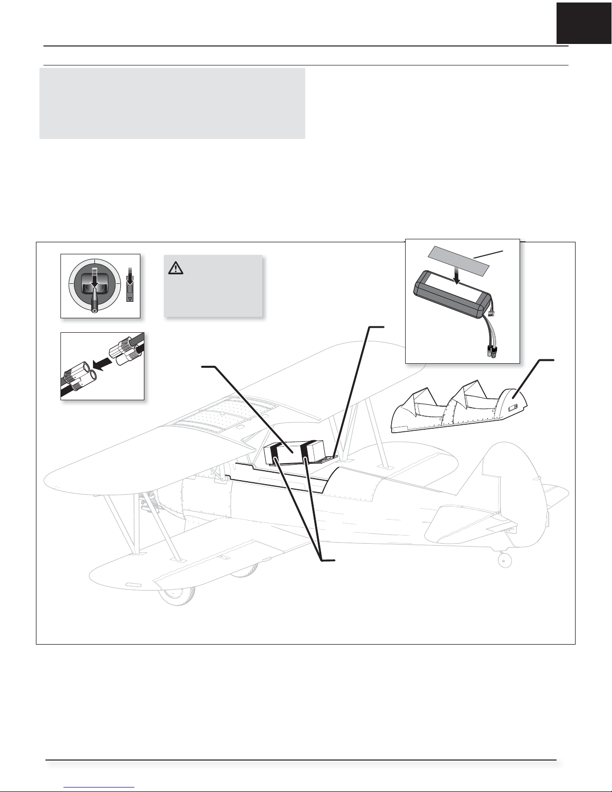
4. Place the aircraft level on its wheels, connect the flight battery to the ESC,
then turn ON the switch. The ESC will produce a series of sounds. 3 flat
tones followed immediately by 2 ascending tones confirm that the LVC is
set correctly for the ESC.
The orange bind LED on the receiver will begin to flash rapidly. DO
NOT remove the bind plug at this time.
5. Take 3 steps away from the aircraft /receiver and then power ON the
transmitter while holding the transmitter bind button or switch. Refer to
your transmitter’s manual for specific binding instructions.
IMPORTANT: Do not to point the transmitter’s antenna directly at the
receiver while binding.
IMPORTANT: Keep away from large metal objects while binding.
6. The receiver is bound to the transmitter when the orange bind light on
the receiver stays orange. The ESC will produce a series of sounds. 3 flat
tones followed immediately by 2 ascending tones. The tones indicate the
ESC is armed, provided the throttle stick and throttle trim are low enough
to trigger arming.
7. Remove the bind plug from the bind port.
IMPORTANT: Once bound, the receiver will retain its bind and last setting
until it has been intentionally changed, even when power is cycled ON and
OFF. However, if you notice that bind has been lost, simply repeat the binding
processs.
SAFE Select OFF Indication
Every time the receiver is powered ON the surfaces will cycle back and forth
once to indicate that SAFE Select has been switched OFF.
The throttle will not arm if the transmitter’s throttle control is not put at the
lowest position. If you encounter problems, follow the binding instructions and
refer to the transmitter troubleshooting guide for other instructions. If needed,
contact the appropriate Horizon Product Support office.
Binding Procedure / Switching ON SAFE Select
IMPORTANT: The included AR636A receiver has been programmed for
operation specifically for this aircraft. Refer to the receiver manual for
correct setup if the receiver is replaced or is used in another aircraft.
CAUTION: When using a Futaba®transmitter with a Spektrum DSM
module, you must reverse the throttle channel and rebind. Refer to
your Spektrum module manual for binding and failsafe instructions. Refer to
your Futaba transmitter manual for instructions on reversing the throttle
channel.
1. Make sure the transmitter is powered off.
2. Move the transmitter controls to neutral (flight controls: rudder, elevators
and ailerons) or to low positions (throttle, throttle trim).*
3. Install a bind plug in the receiver bind port.
4. Place the aircraft level on its wheels, connect the flight battery to the ESC,
then turn ON the switch. The ESC will produce a series of sounds. 3 flat
tones followed immediately by 2 ascending tones confirm that the LVC is
set correctly for the ESC. The orange bind LED on the receiver will begin to
flash rapidly.
5. Remove the bind plug from the bind port.
6. Take 3 steps away from the aircraft /receiver and then power ON the
transmitter while holding the transmitter bind button or switch. Refer to
your transmitter’s manual for specific binding instructions.
IMPORTANT: Do not to point the transmitter’s antenna directly at the
receiver while binding.
IMPORTANT: Keep away from large metal objects while binding.
7. The receiver is bound to the transmitter when the orange bind light on
the receiver stays orange. The ESC will produce a series of sounds. 3 flat
tones followed immediately by 2 ascending tones. The tones indicate the
ESC is armed, provided the throttle stick and throttle trim are low enough
to trigger arming.
IMPORTANT: Once bound, the receiver will retain its bind and last setting
until it has been intentionally changed, even when power is cycled ON and
OFF. However, if you notice that bind has been lost, simply repeat the binding
processs.
SAFE Select ON Indication
Every time the receiver is powered ON the surfaces will cycle back and forth
twice with a slight pause at neutral position to indicate that SAFE Select is
switched ON.
The throttle will not arm if the transmitter’s throttle control is not put at the
lowest position. If you encounter problems, follow the binding instructions and
refer to the transmitter troubleshooting guide for other instructions. If needed,
contact the appropriate Horizon Product Support office.
*Failsafe
If the receiver loses transmitter communication, the failsafe will activate. When activated, failsafe moves the throttle channel to its preset
failsafe position (low throttle) that was set during binding. All other channels move to actively level the aircraft in flight.
Switching ON SAFE Select Binding Sequence