Horst Welding CHC25 User manual

HORST WELDING
8082 Rd 129 Listowel, ON N4W 3G8 Canada
519-291-4162
1-866-567-4162
Fax 1-519-291-5388
Rev 220620 HWA00102 CHC.Header Wagon Assembly.Ref.Book.SIS.190220
Assembly
and Reference Book
Please review and understand the assembly manual d understand the assembly manual
before attempting to assemble this machinery. before attempting to assemble this machinery.
PRINTED IN CANADA
!
!
CAUTION
Operational Hazard
Personal Protection Equipment
(PPE) is required during
assembly.
SNL00001
!
CAUTION
Operational Hazard
Machine assembly should be done by
Two Wheel Steer HEADER WAGON
CHC25, CHC30, CHC36

2
Reference Information � � � � � � � � � � � � � � � � � � 2
Alignment . . . . . . . . . . . . . . . . . . . . . . . . . . . . . . .2
. . . . . . . . . . . . . . . . .3
Tire Pressure Table. . . . . . . . . . . . . . . . . . . . . . . .3
. . . . . . . . . . . .3
California Proposition 65 . . . . . . . . . . . . . . . . . . .4
Assembly Safety � � � � � � � � � � � � � � � � � � � � � � � 4
Bolt Torque Table . . . . . . . . . . . . . . . . . . . . . . . . .5
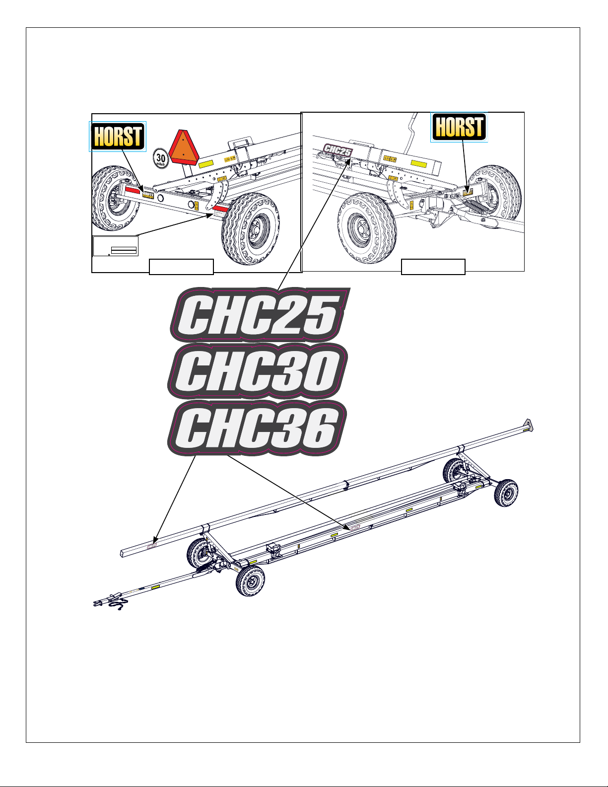
Label Layout CHC Series . . . . . . . . . . . . . . . . . . .6
Product labels and Serial Plate . . . . . . . . . . . . . . . . 6
. . . . . . . . . . . . . . . . . . 6
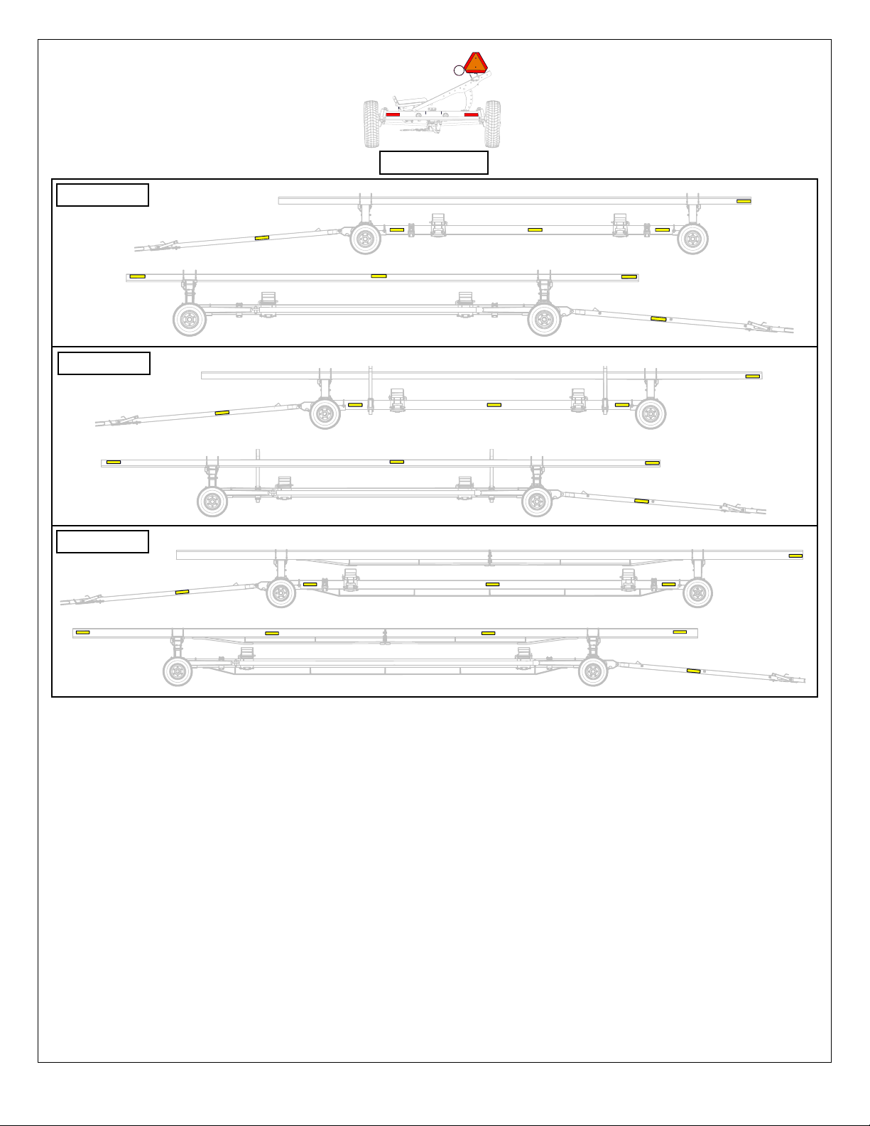
Safety Label Layout . . . . . . . . . . . . . . . . . . . . . . . . . 7
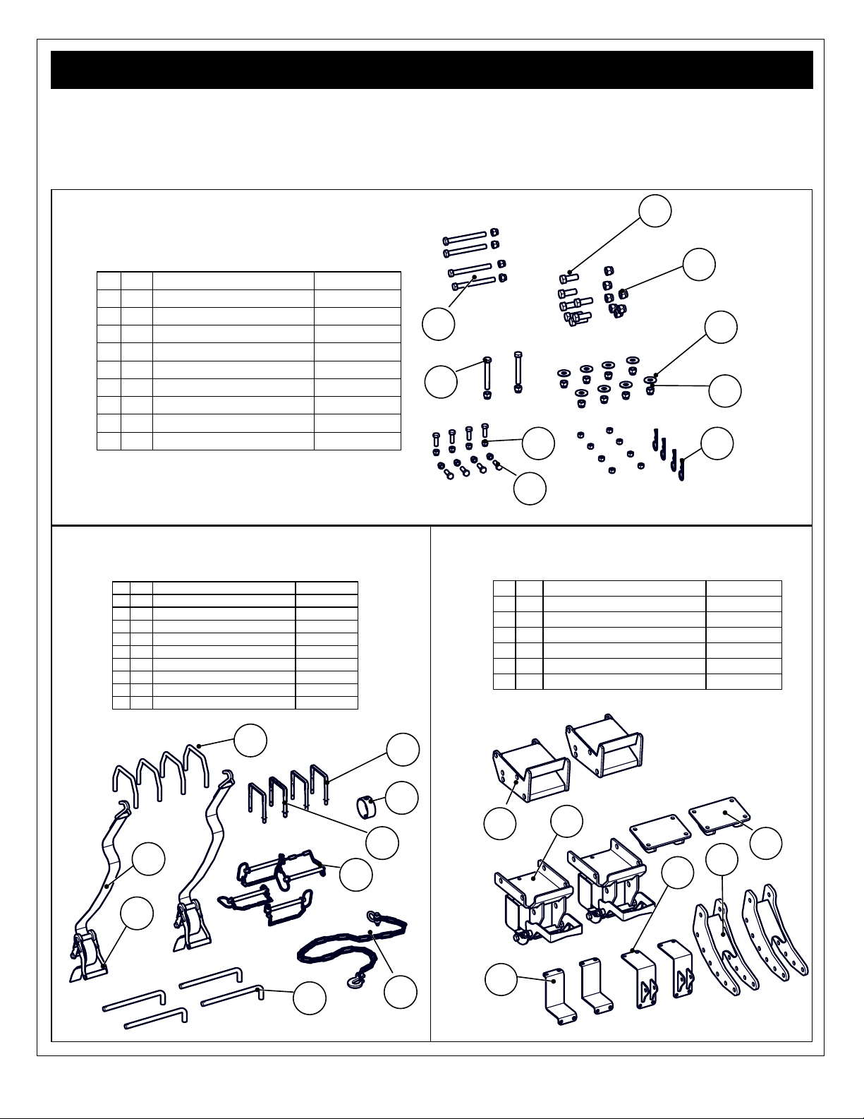
Parts � � � � � � � � � � � � � � � � � � � � � � � � � � � � � � � � � 9
Hardware Bag. . . . . . . . . . . . . . . . . . . . . . . . . . . .9
Parts Bag . . . . . . . . . . . . . . . . . . . . . . . . . . . . . . .9
Crated. . . . . . . . . . . . . . . . . . . . . . . . . . . . . . . . . .9
Chassis Parts . . . . . . . . . . . . . . . . . . . . . . . . . .10
Assembly � � � � � � � � � � � � � � � � � � � � � � � � � � � � 11
STEP 1 . . . . . . . . . . . . . . . . . . . . . . . . . . . . . . . . 11
Reach & Bottom Rail. . . . . . . . . . . . . . . . . . . . . . . . 11
STEP 2 . . . . . . . . . . . . . . . . . . . . . . . . . . . . . . . .12
Mount Tongue Assembly: . . . . . . . . . . . . . . . . . . . . 12
Safety Chain: . . . . . . . . . . . . . . . . . . . . . . . . . . . . . 12
Wheels . . . . . . . . . . . . . . . . . . . . . . . . . . . . . . . . . . 12
STEP 3 . . . . . . . . . . . . . . . . . . . . . . . . . . . . . . . .13
Diagonal Channels . . . . . . . . . . . . . . . . . . . . . . . . . 13
STEP 4 . . . . . . . . . . . . . . . . . . . . . . . . . . . . . . . .14
Top Rail . . . . . . . . . . . . . . . . . . . . . . . . . . . . . . . . . . 14
. . . . . . . . . . . . . . 14
. . . . . . . . . . . . . 14
STEP 5 . . . . . . . . . . . . . . . . . . . . . . . . . . . . . . .15
Ratchet Strap . . . . . . . . . . . . . . . . . . . . . . . . . . . . . 15
Header Pad. . . . . . . . . . . . . . . . . . . . . . . . . . . . . . . 15
Accessories � � � � � � � � � � � � � � � � � � � � � � � � � � 16
Tongue Spring Balancer Kits Assembly . . . . . . .16
Tongue Spring Balancer - Wagon Models. . . . . . . . 16
LK Series Road Signal Kit . . . . . . . . . . . . . . . . .17
Rear: . . . . . . . . . . . . . . . . . . . . . . . . . . . . . . . . . . . . 17
Front:. . . . . . . . . . . . . . . . . . . . . . . . . . . . . . . . . . . . 17
Reach Tube. . . . . . . . . . . . . . . . . . . . . . . . . . . . . . . 17
. . . . . . . . . . . . . . .18
. . . . . . . . . . . . . . . . . . . . . . . . . . . 18
CHC Replacement . . . . . . . . . . . . . . . . . . . . . . . . . 18
HBAFK Honey Bee AirFLEX®Pad Adapter Kit . .19
Whats Included: . . . . . . . . . . . . . . . . . . . . . . . . . . . 19
Honey Bee AirFLEX®Adapter . . . . . . . . . . . . . . . . . 19
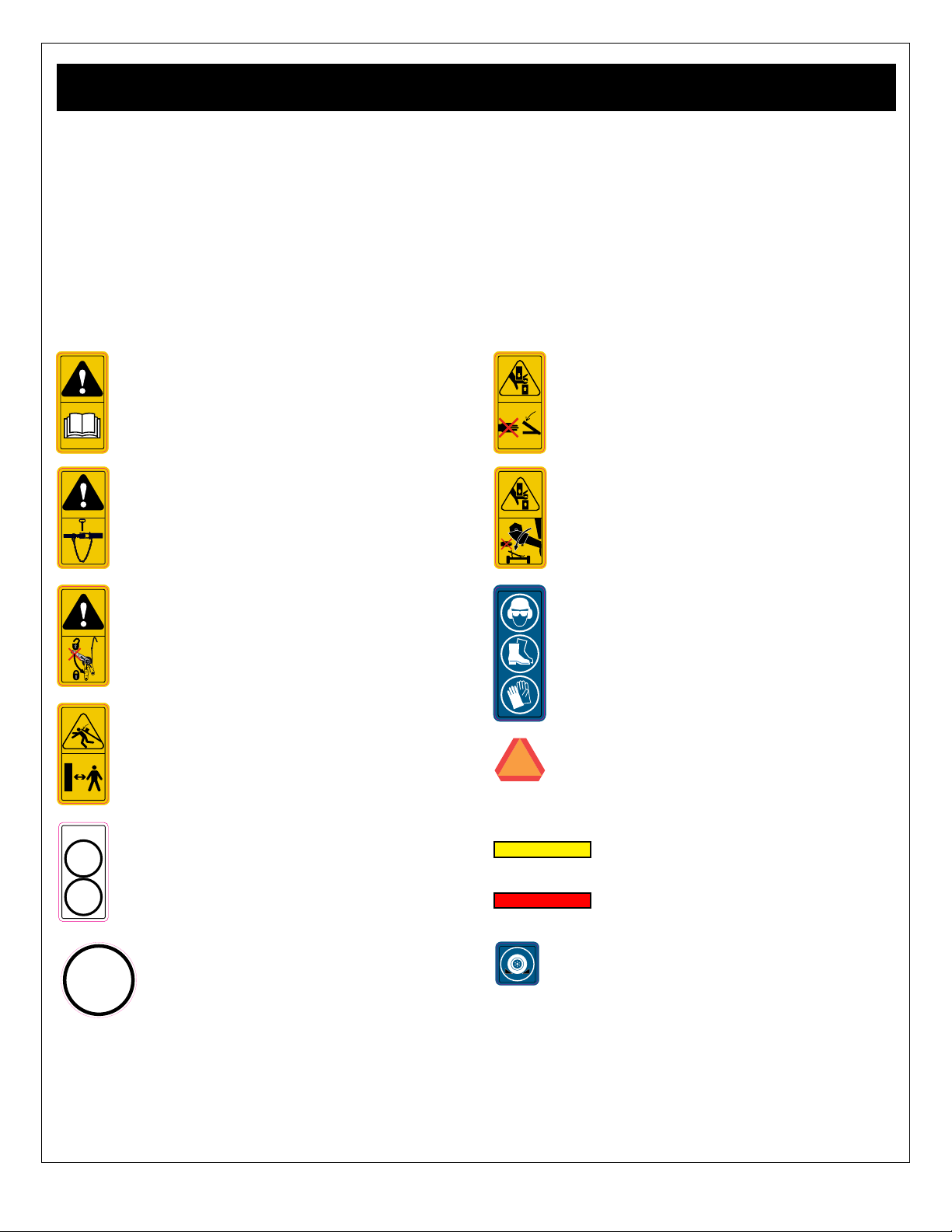
!
CAUTION
Prepare
Read and understand ALL safety and
operating instructions in the owner
manual, read and understand ALL
safety labels located on the machine.
SL00004
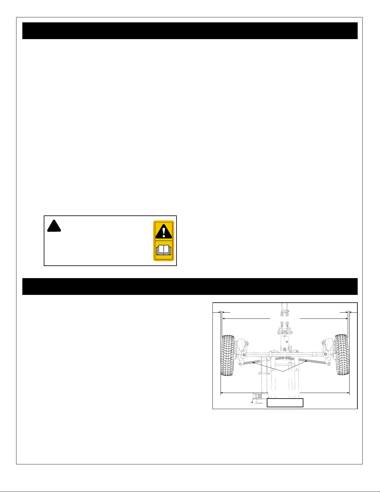
Alignment is set at the factory with proper toe-in settings on the front
steering axles. Check alignment as outlined below.
To check toe-in:
• Position the tongue parallel to the reach tubes
• Run a string or straight edge from front to back along the outside
of the front and rear wheels, check both sides.
•
• Measure across the front of the wheels, - dimension A
• Then across the back of the wheels, - dimension B.
• Dimension A measurement should be approximately 0.32 -
If adjustment is required, loosen the tie rod end jam nuts, then:
• Adjust as required by turning the two tie rods.
•
0.6cm - 0.32cm
1/16” - 1/8”
0.16cm - 0.32cm
1/16” - 1/8”
Dimension A
Dimension B
Tie Rods
Front axle

3
tires are
inspected after unit is loaded. Do not exceed maximum recommended tire
pressure.
It is an extremely important safety procedure to apply and
maintain proper wheel mounting torque on your trailer axle.
Torque wrenches are the best method to assure the proper
amount of torque is being applied to a fastener.
Wheel lugs should be torqued before rst road use and after
each wheel removal. Check and re torque after the rst 10
miles, 25 miles, and again at 50 miles. Check periodically
thereafter.
Note: Wheel lugs must be applied and maintained at the
proper torque levels to prevent loose wheels, broken studs,
and possible dangerous separation of wheels from your axle.
1. Start all lugs by hand to prevent cross threading.
2. Tighten lugs in sequence, as shown in the diagram.
3. Tighten the lugs - see chart
Wheel Lug Torque Sequence
lbs-ft
N-m
lbs-ft
N-m
1/2" 90 122 65 88
1/2" (brake drum) 100 136 75 102
9/16" 120 163 90 122
5/8 180 244 130 176
3/4 300 407 220 298
Torque
Dry
Torque
Lubricated
Wheel Nut / Bolt
Size
5 Bolt 6 Bolt 8 Bolt 10 Bolt
55
5
59
4
4
4
4
3
3
3
3
22
2
2
1
1
1
1
6
6
6
7
7
8
810
Tire PSI kPa
Tires: 20.5 x 8 - 10 (F Range)
tire 105 723
Tires: 26 x 12 12 ply tire 62 427
Tires: 235/85 R16 (F Range)
Highway Trailer tire 95 655
Tires: 11L x 15 (F Range) Highway
90 620
225/75 R15 Load Range D 65 448
The SIS and standard is part of the US Federal Regulation 49CFR Part 562.
on public roads.
Header Wagons is 30 mile/h.
You may see a warning label similar to the following:
WARNING
Cancer and Reproductive Harm
www.P65 Warnings.ca.gov
This warning is required by California Proposition 65 (Prop 65), which is meant to notify California residents of exposures
30
mile/h
IL00009
S
.
I
.
S
S
y
m
b
o
l
:
U
.
S
.
m
o
d
e
l
s
o
n
l
y

4
Read and understand the Assembly Manual and all safety signs before starting.
!
CAUTION
Operational Hazard
Personal Protection Equipment
(PPE) is required while assembling
or maintaining this machine.
SNL00001
!
CAUTION
Heavy or bulky parts
lifting equipment or ask for help when lifting or
!
This Safety Alert Symbol means:
ATTENTION!
BECOME ALERT!
YOUR SAFETY IS INVOLVED!
manual. When you see this symbol, read and understand the message, be alert to the potential
hazard in the message. Follow the instructions in the safety message.
1. Follow good safety practices:
•
• Be sure electrical outlets and tools are properly
grounded.
• Use adequate light for the job at hand.
2.
slipping or tripping.
3. Position in a large open area to allow access from all
sides during assembly.
4. When using lifting equipment, place jack stands
under the machine to securely stabilize it before
working on, beside or under it during assembly.
5.
obstructions when lifting the machine during
assembly. Contact with power lines can cause
electrocution. Contact with obstructions can damage
components or cause them to fail.
6.
ask for help.
7. Use properly sized tools, stands, jacks and hoists at
all times.
8.
recheck before using the machine

5
B
A
B
A
8.8 10.9
SAE 2 SAE 5 SAE 8
These tables are offered as the suggested maximum torque values for dry (not lubricated) threaded products and
are only a general guide.
Check tightness of bolts periodically, replace hardware with the same strength bolt.
Torque specication for bolts are identied by their head markings as shown.
See the “Wheel Torque Specication” page for wheel bolt /nut torque settings
METRIC TORQUE SPECIFICATIONS
SAE TORQUE SPECIFICATIONS
N-m lbs-ft N-m lbs-ft N-m lbs-ft N-m lbs-ft
10 mm 6 x 0.75 --- --- --- --- 6 x 1.0 11.3 8.3 16.5 12.2
13 mm 8 x 1.0 27 20 38 28 8 x 1.25 27.3 20.1 40.1 29.6
16 mm 10 x 1.25 52 38 73 54 10 x 1.5 54 40 49 36
18 mm 12 x 1.25 95 70 135 100 12.1.75 93 69 137 101
21 mm 14 x 1.5 150 111 210 155 14 x 2.0 148 109 218 161
24 mm 16 x 1.5 225 166 315 232 16 x 2.0 230 170 338 249
27 mm 18 x 1.5 325 240 460 339 18 x 2.5 329 243 469 346
30 mm 20 x 1.5 460 339 640 472 20 x 2.5 464 342 661 487
34 mm 22 x 1.5 610 450 860 634 22 x 2.5 634 468 904 667
36 mm 24 x 2.0 780 575 1100 811 24 x 3.0 798 588 1136 838
41 mm 27 x 3.0 --- --- --- --- 27 x 3.0 1176 867 1674 1234
46 mm 30 x 2.0 --- --- --- --- 30 x 3.0 1597 1178 2274 1677
Class 10.9Class 8.8
Wrench
Size:
"A"
Thread Size:
"B"
Fine
Thread Size: "B"
Coarse
Class 10.9 Class 8.8
lbs-ft.N-m lbs-ft N-m lbs-ft N-m lbs-ft N-m lbs-ft N-m lbs-ft N-m
7/16” 1/4-28 6 8.1 10 13.6 14 19.0 1/4-20 5 6.8 8 10.8 12 16.3
1/2” 5/16-24 13 17.6 19 25.7 27 36.6 5/16-18 11 14.9 17 23.0 25 33.9
9/16” 3/8-24 23 31.2 35 47.4 49 66.4 3/8-16 20 27.1 31 42.0 44 59.6
5/8” 7/16-20 36 48.8 55 74.5 75 101.6 7/16-14 32 43.4 49 66.4 70 94.9
3/4” 1/2-20 55 74.5 85 115.2 120 162.6 1/2-13 49 66.4 75 101.6 107 145.0
13/16” 9/16-18 79 107.0 122 165.3 172 233.1 9/16-12 70 94.9 109 147.7 154 208.7
15/16” 5/8-18 110 149.1 170 230.4 240 325.2 5/8-11 97 131.4 150 203.3 212 287.3
1-1/8” 3/4-16 192 260.2 297 402.4 420 569.1 3/4-10 173 234.4 266 360.4 376 509.5
1-5/16” 7/8-14 184 249.3 474 642.3 668 905.1 7/8-9 166 224.9 429 581.3 606 821.1
1-1/2” 1.0-12 274 371.3 705 955.3 995 1348.2 1.0-8 250 338.8 644 872.6 909 1231.7
SAE 8SAE 2 SAE 5 SAE 8
Wrench
Size:
"A"
Thread
Size: "B"
Fine
Thread
Size: "B"
Coarse
SAE 2 SAE 5

6
CHC25, CHC30, CHC36
Product labels and serial plate locations on the equipment are shown in the illustrations below. The CHC label locations
are similar for all models, unless otherwise indicated.
Manufactured by
HORST WELDING
MODEL NO.
SERIAL NO.
MADE IN CANADA
• Be sure that the installation area is clean and dry.
•
•
•
•
• Slowly peel back the remaining paper and carefully smooth the remaining portion of the sign in place.
• Small air pockets can be pierced with a pin and smoothed out using the piece of sign backing paper.

7
CHC 25
CHC30
CHC36
Rear all CHC
ASTM D-4956 compliant.
Red x 2 all models
Yellow x 10
Yellow x 9
Yellow x 9
30
mile/h
IL00009
S
.
I
.
S
S
y
m
b
o
l
:
U
.
S
.
m
o
d
e
l
s
o
n
l
y

8
SL00001H
SL00003H
SL00001
SL00001H
SL00003H
SL00001
Tongue
Right Side
Left Side
new labels must be
applied. New safety
your dealer or contact
Horst Wagons
label locations are similar for all models, unless otherwise indicated.
of the equipment or particular equipment feature that requires your SAFETY AWARENESS.
CHC 36 only
SL00006
SL00003H
SNL00002
SNL00002
SNL00002
SNL00002
50
km/h
30
mile/h
MAXIMUM
IL00007
SL00004
SL00005
SNL00001
WARNING
Cancer and
Reproductive Harm
www.P65 Wa
30
mile/h
IL00009
S
.
I
.
S
S
y
m
b
o
l
:
U
.
S
.
m
o
d
e
l
s
o
n
l
y
SL00002

9
potential injury or death, and is important to follow these points to help keep your implement safe for you and others who
may be using it.
• Keep safety signs clean and legible at all times.
•
illegible.
• Replaced parts that displayed a safety sign should
also display the current sign.
•
displayed with it. Use this part number when ordering
replacement parts.
•
Distributor or the factory order desk.
SL00001
SL00002
SL00003
SL00004
SL00005
SL00006
SNL00001
Caution: read and understand ALL safety and
operating instructions in the manual, read and
understand ALL safety labels located on the
this equipment is an informed SAFE operator.
Caution: Accidental wagon disconnection on
a public road could result in death or serious
injury and/or implement damage. Before
hitch
pin is installed.
Caution: an unsecured load may fall from the
wagon and could result in death or serious injury
and/or implement damage. Before transport on
public roads always check the ratchet straps
are tight and in locked position.
Caution: Do not stand under or directly in front
of the top rail while it is being adjusted, potential
collision exists if the rail drops suddenly and
could result in death or serious injury.
hazard and could result in a serious injury. Use
caution and be aware of parts as they are being
Caution: Loading the header on the wagon
presents a potential pinch hazard and could
result in a serious injury. Use caution and be
aware as the header is loaded on potential
pinch points on the header pads and the top
rail.
Caution: Personal Protection Equipment (PPE)
is required when operating or maintaining this
machine. Failure to wear PPE will result in
personal injury.
marking of implements for length / width.
50
km/h
30
mile/h
MAXIMUM
IL00007
Caution: Wagon components are rated at 50
km/h (30 mile/h) maximum speed. Potential for
road users that the wagon displaying the sign
maximum road speed of 40 km/h
(25 mile/h) or less. Ensure the sign is in place
SNL00002
Caution: Block or chock the wheels. Loading
or unloading the wagon presents a potential
when loading or unloading or storing the wagon.
30
mile/h
IL00009
S
.
I
.
S
S
y
m
b
o
l
:
U
.
S
.
m
o
d
e
l
s
o
n
l
y
Header Wagons is 30 mile/h.
U�S� only does not apply in Canada

10
Check for missing or damaged parts� Contact the shipping company if
damage is found� For missing parts contact your dealer
4
x8
8
x7
3
x4
2
x14
6
x7
x2
1
x16
9
7
x8
x4
5
ID Qty Description Used.In.Model
12 5/8 x 4 1/2 Hex Bolt & Locknut All
214 5/8 Lock Nut All
34 5/8 x 6 Bolt & Locknut All
48 5/8 Flat Washer All
54 Hitch Pin (480-009) All
67 3/4" Locking nut CHC36
78 1/2" x 1 1/2" Hex Bolt All
87 3/4 x 2 Hex Bolt CHC36
916 1/2" Lock All
x2
21
19
x2
x2
20
x2
24
x2
23
22
x2
ID Qty Description Used.In.Model
19 2 Top Rail Mount All
20 2 Top Rail Upright Adjustment Assy All
21 2 Moveable Ratchet Mount Assembly All
22 2 Shoe Tube Cradle Assembly All
23 2 CHCUS Lower Shoe Assembly All
24 2 Ratchet Inner Bracket All
x4
10
17
x4
13
18
x4
x4
12
11
14
x4
15
x2
x2
16
ID Qty Description Used.In.Model
10 4 5/8 Bottom Rail U-Bolt All
11 1 CHC Safety Chain Assembly All
12 4 U Bolt .5 x 4 x 7.5 CHC36
13 1 Retainer Ring All
14 4 Shoe Heel Pin All
15 2 CHC Strap Ratchet Kinedyne P/N 804 All
16 2 2" x 52" nylon strap All
17 4 Draw Pin (5/8) c/w Chain & Lynch Pin All
18 4 U Bolt .5 x 4 x 5.5 CHC25 & 30

11
34
x4
25
x2
33
32
26
28
x2
35
36
31
29
30
27
!
CAUTION
Operational Hazard
Personal Protection Equipment
(PPE) is required while assembling
or maintaining this machine.
SNL00001
ID Qty Description Used.In.Model
25 1 13' Round Reach CHC25 & 30
26 1 Bottom Rail CHC25 & 30
27 1 24' Wheelbase HD Bottom Rail CHC36
28 2 Top Rail 36' (4" X 6" X .188 HSS)(Bridged&Split) CHC36
29 1 TOP RAIL 26' (4" X 4" X .188 HSS) CHC25
30 1 CHC Complete Front Axle All
31 1 CHC Complete Rear Axle All
32 1 CHC Tongue Assembly All
33 2 Top Rail Support Channel All
34 4 20.5 x 8-10 (F Range) Tire on 10X6X6 Rim All
35 1 TOP RAIL 31' (4" X 4" X .188 HSS) CHC30
36 1 20ft Reach CHC36
!
CAUTION
Heavy or bulky parts
lifting equipment or ask for help when lifting or

12
This assembly manual is for CHC25, 30, 36 Header Wagon models. The CHC30 is used as an example in the illustrations
1. Clear the area of bystanders, especially small children.
3. Prepare a clean, clear work area that is accessible from all sides.
STEP 1
1. Set the axle assemblies up on
wheel stands, ensure they are
during assembly.
2. Front axle: Insert the reach tube to the reach
3.
4.
brackets on both axles. Center the rail between front and back axles and
Reach
Bottom Rail
(CHC36 shown)
Cradle
Bracket
Reach tube
Retainer ring
!
CAUTION
Heavy or bulky parts
lifting equipment or ask for help when lifting or

13
STEP 2
Wheel assembly
1.
2.
3.
a guide.
4. Repeat for remaining wheels
5.
1.
1. Position the tongue on the bracket assembly, and from the left side
of the tongue bracket, insert the hex bolt.
2. Thread the locking nut onto the bolt and tighten until the bolt is snug
against the plates.
3.
1. Attach the safety chain to the
the coupling link on the chain.
2. Assemble the link with the
coupling bolt and locknut as
shown.
Tongue
Assembly
Coupling
link
!
CAUTION
Heavy or bulky parts
-
!
CAUTION
Operational Hazard
Chock wheels while
assembling the wagon
SNL00002

14
STEP 3
!
CAUTION
Heavy or bulky parts
lifting equipment or ask for help when lifting or
1.
remaining adjuster.
bracket
2. Next, mount the diagonal channel to the left cast
bushings on top of axles, and to the top hole on
3.
the bolt and tighten until the bolt is snug against the
4. Repeat for the remaining axle.
5. Pin the top rail mount to the top of the diagonal
channel.
6.
Top rail mount
Diagonal channel
Cast bushing
!
CAUTION
Operational Hazard
Chock wheels while
assembling the wagon
SNL00002

15
Secure top rail
Bolt top rail
sections
STEP 4
1�
Note: CHC25 & 30 is a 4.0 x 4.0 one piece top rail.
2�
spaced on the diagonal channels from front to back. Clamp or hold the rail
in place.
3.
Repeat for remaining mount.
4. Further adjustment to the top rail position may be necessary depending on
30
mile/h
IL00009
S
.
I
.
S
S
y
m
b
o
l
:
U
.
S
.
m
o
d
e
l
s
o
n
l
y
1.
u-bolt and nuts (if attaching the SIS see below)
2.
3. Loosely fasten the nuts.
4.
the nuts and bolts.
An SIS is required for U.S. customers that intend to
1.
2. Secure with the two bolts and nuts.
3. Loosely fasten with bolts and nuts.
4.
the nuts and bolts.
SIS bracket

16
STEP 5
1. Set the ratchet outer mount on the bottom rail at the preferred location
2.
hex bolts and lock-nuts.
3. Tighten the nuts and bolts
4. Fasten the ratchet to the outer mount with the existing bolt and
locknut.
5. Thread the strap into the ratchet and wind it up.
1.
pins, secure with hitch pins.
2.
3.
the preferred location.
4. Swing the latch up to the quick release catch.
5. Engage the quick release by pulling up on the quick release handle and
lock the header pad in place.
6. Repeat process for second header pad.
Latch
Catch
Outer mount
Inner bracket
Shoe heel pin
Hitch pin
Quick release
handle

17
This instruction sheet applies to:
WA-SBD Double Spring Balancer Assembly
WA-SB Single Spring Balancer Assembly
!
This Safety Alert symbol means
ATTENTION! BECOME ALERT! YOUR SAFETY IS
INVOLVED!
in this instruction, as well as on the machine and in the
operators manual. When you see this symbol, be alert to
any hazards and the possibility of personal injury. Follow the
instructions in the safety message.
•
angle.
• Carefully preassemble the spring balancer assembly as
shown.
• Mount the balancer assembly spring end to the mount
plate on the tongue with the bolt, lock washer and nut.
welded to the tongue)
• Mount the opposite end to the mounting hole in the tongue
bracket with the bolt, lock washer and nut.
•
Assembly process is the same for either balancer accessory
!
CAUTION
Operational Hazard
Chock wheels during
SNL00002
Double Spring
Balancer
Single Spring
Balancer
!
CAUTION
Operational Hazard
Personal Protection Equipment
(PPE) is required while working in
and around this machine.
SNL00001
!
WARNING
Pinch Point Hazard
Be aware of pinch points at the tongue
Preassemble
Preassemble

18
This instruction sheet applies to:
Light bar assembly and mount.
• Assemble the light bracket top plate to the light bar, using two
•
header wagon, fasten the light bracket bottom brace using the
The instructions generally apply to all LK signal kits and CHC header
Light Bracket
Top Plate
Light Bar
Light Bracket
Bottom Brace
Rear
CHC
Front
CHC
Do not fully tighten until all the clamps are in place.
• Route the long cable from the light bar along the reach tube, to
the front of the wagon.
•
top plate, take out any cable slack to the light bar.
•
on the rear
head screws, pull up any cable slack.
•
on the front
head screws, pull up any cable slack.
•
tongue bracket, pull up slack, ensure there is enough cable slack
• Fasten the cable to the three
hinge.
•
range of motion and check that
the cable is free from stretching,
binding or pinching, tighten up all
clamps.
• Place and fasten the remaining
equally along the reach tube.
• Tighten up all remaining clamps
Tongue
CHC
Reach Tube
CHC
Slack
Tongue cable
clamp

19
!
This Safety Alert symbol means
ATTENTION! BECOME ALERT! YOUR SAFETY IS INVOLVED!
and in the operators manual. When you see this symbol, be alert to any hazards and the possibility of
personal injury. Follow the instructions in the safety message.
•
•
•
shoe heal pins.
• Ensure the hitch pins are securely in place.
• Release the shoe lock handle and locate base pad on rail
to desired position, lock the handle.
!
CAUTION
Operational Hazard
Chock wheels during
SNL00002
!
CAUTION
Operational Hazard
Personal Protection Equipment
(PPE) is required while working in
and around this machine.
SNL00001
This pad kit is an upgrade replacement for the CHC Standard
Lower Shoe Assembly
Upper Shoe Assembly
Hitch Pin
Shoe Heal Pin
Lower Shoe Assembly
Upper Shoe Assembly
Hitch Pin
Shoe Heal Pin
!
CAUTION
Heavy or bulky parts
-
Check for missing or damaged parts. Contact the shipping company if damage is found.
For missing parts call your dealer. To order replacement parts call you dealer or go to www.horstwagons and click on
‘Parts

20
®
!
This Safety Alert symbol means
ATTENTION! BECOME ALERT! YOUR SAFETY IS INVOLVED!
and in the operators manual. When you see this symbol, be alert to any hazards and the possibility of
personal injury. Follow the instructions in the safety message.
•
Bee adapters.
• Find the mid paddle support on you Honey
Bee AirFLEX® header and carefully slide the
adapter on to the support.
• Secure the adapter with the bolt and lock nut.
• Repeat for the second adapter.
• Check lock nuts and bolts are tight.
®
The HBAFK Honey Bee AirFLEX® Pad Adapter Kit is designed to bolt on to the Honey Bee AirFLEX ® mid paddle
!
CAUTION
Operational Hazard
Personal Protection Equipment
(PPE) is required while working in
and around this machine.
SNL00001
This is a one time installation, once installed the adaptors can remain on the header.
!
CAUTION
Heavy or bulky parts
-
Check for missing or damaged parts. Contact the shipping company if damage is found.
For missing parts call your dealer. To order replacement parts call you dealer or go to www.horstwagons and click on
‘Parts
The Honey Bee adapter works with the following Horst header wagons:
CHC30 & CHC36
2 pcs Horst / Honey Bee Pad Adapter
2 pcs 3/4-10 lock nut
Honey Bee pad
adapter
Honey Bee AirFLEX ®
mid paddle support
This manual suits for next models
2
Table of contents
Other Horst Welding Tractor Accessories manuals
Popular Tractor Accessories manuals by other brands

Arctic
Arctic Sectional Sno-Pusher CD-6.5 owner's manual

Ventrac
Ventrac KH500 Versa-Loader Owner/operator's manual & parts list

matev
matev FPS JD-2036R operating manual

Toro
Toro 136-8545 installation instructions

Carolina
Carolina Swing Boom Cutter Owner's/operator's manual

Winton
Winton WTL Series owner's manual