Master Language is English Hot Runner System Installation Guide SVC-17-0001_EN-Rev13
RESTRICTED: Property of Synventive. - 359 - All rights reserved. Errors and omissions excepted
For limited third party distribution based on need and intended use. © 2021 Synventive Molding Solutions
H O T R U N N E R T E C H N O L O G Y
Hot Runner System Installation Guide
Service and Maintenance / Nozzle 16E-06 / 22E-06 Series
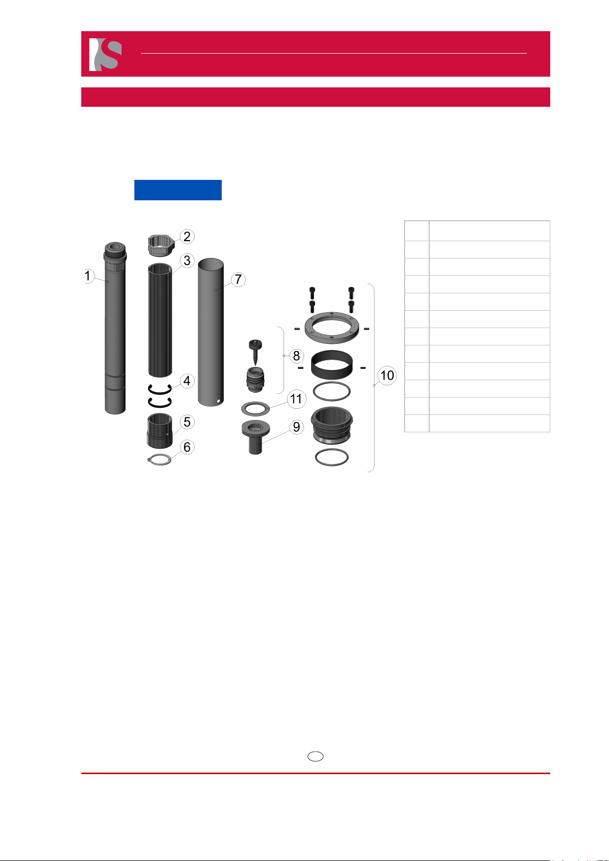
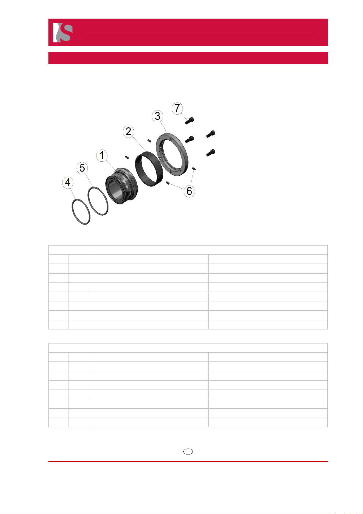
10.1.4 Nozzle 16E-06 / 22E-06 Series
NOTICE
Always tighten the screws to the torque specified in the respective table in section 13.
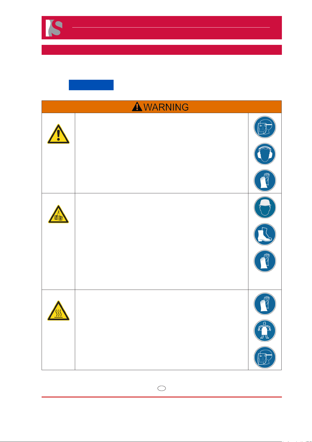
Hazard of Pressurized Air
Pressurized air blow can result in hot plastic or foreign bodies entering the
eyes, causing vision damage.
Following work must be carried out by qualied and experienced persons.
Use personal protective equipment: Face protection, hearing protection and
gloves.
For rst aid contact your medical / safety representing.
Heavy Weight Hazard
Transport and lifting equipment should be operated only by trained
personnel.
Operate lifting and transport equipment slowly and carefully to avoid uncontrolled
swinging of the manifold.
Lifting and transport equipment for lifting Hot Runner Systems shall be approved
and properly rated taking into account the weight and size of the manifold.
When unpacking the Hot Runner System, there is a risk of injury due to falling
parts and sharp edges. Maintain a minimum distance of 1 m from the Hot Runner
System.
Use personal protective equipment, such as head gear, safety shoes and work
gloves.
For rst aid contact your medical / safety representing.
Hot Surfaces Hazard
Contact between the skin and hot surfaces could result in burns.
Use personal protective equipment, such as gloves, apron, sleeves and face
protection, to guard against burns.
When servicing or handling the hot runner system outside the manifold plates
or the injection molding machine, care must be taken to heed the hot surface
exposure warnings.
For rst aid contact your medical / safety representing.