10
ROOM CONSTRUCTION -
GENERAL INFORMATION
A. FRAMING
2” x 4” any suitable wood material,
16” o.c.
B. CEILING LIGHT
No higher than 7’0”.
C. INSULATION
R11 Fiberglass with foil back in walls
and ceiling, foil facing into room.
D. DRYWALL
See local codes. Is not required in
most residences. See local codes
commercial. If drywall is used, apply
1” x 2” nailers so that wall and ceiling
boards can be attached to solid wood.
E. PANELING
Use kiln-dried, clear, T&G softwood
such as California Redwood, Western
Red Cedar, Alaska Yellow Cedar, pine,
spruce or other suitable wood material
(with moisture content not exceeding
11%).
F. BENCHES
Use matching wood of vertical grain.
Fasten from bottom to prevent
burning of bathers.
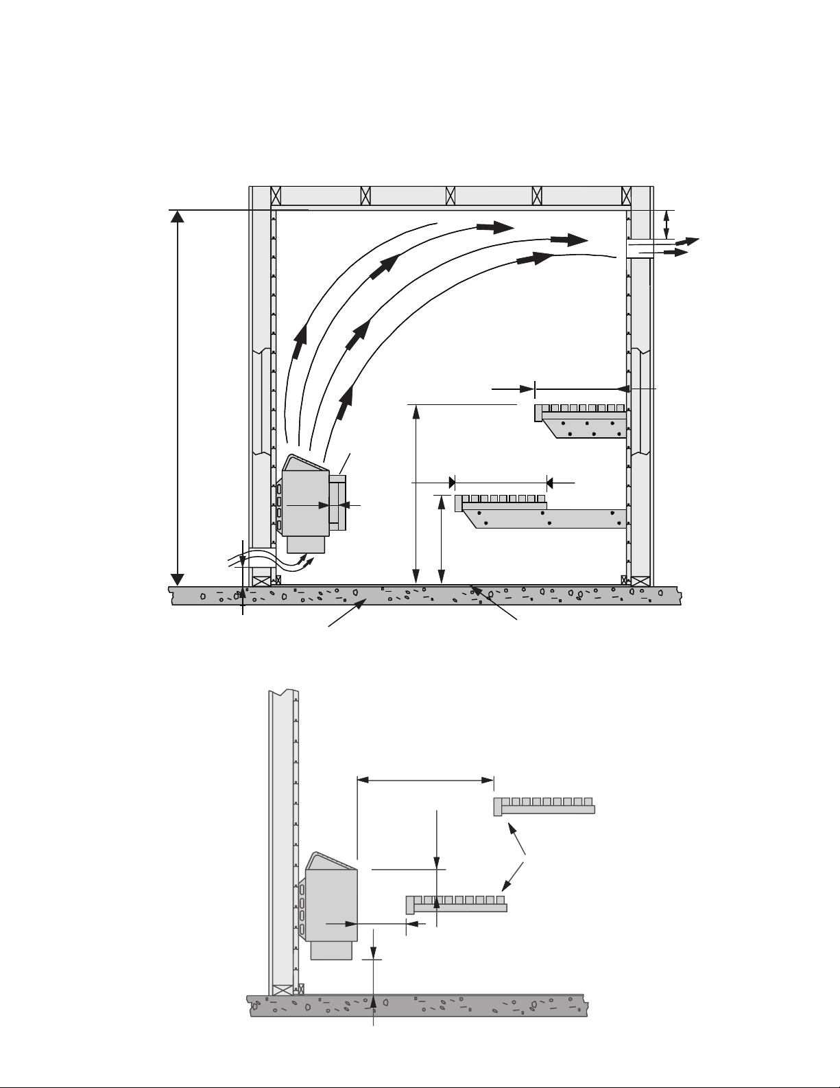
G. HEATER FENCE
Is necessary for safety and should
be constructed of 1” x 4” or 2” x 4”
softwood to match sauna interior. See
gures 2 - 4 clearances from sauna
heater. Fence should attach to wall
and should not be placed higher than
top of heater below rock line.
H. DOOR
Must open out and should not have a
lock.
I. FLOORING
Concrete, ceramic tile, or heavyduty
vinyl.
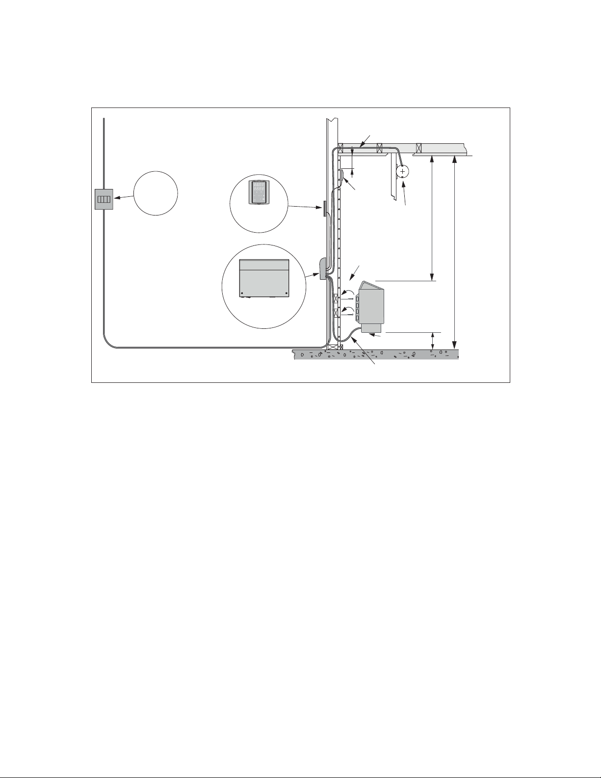
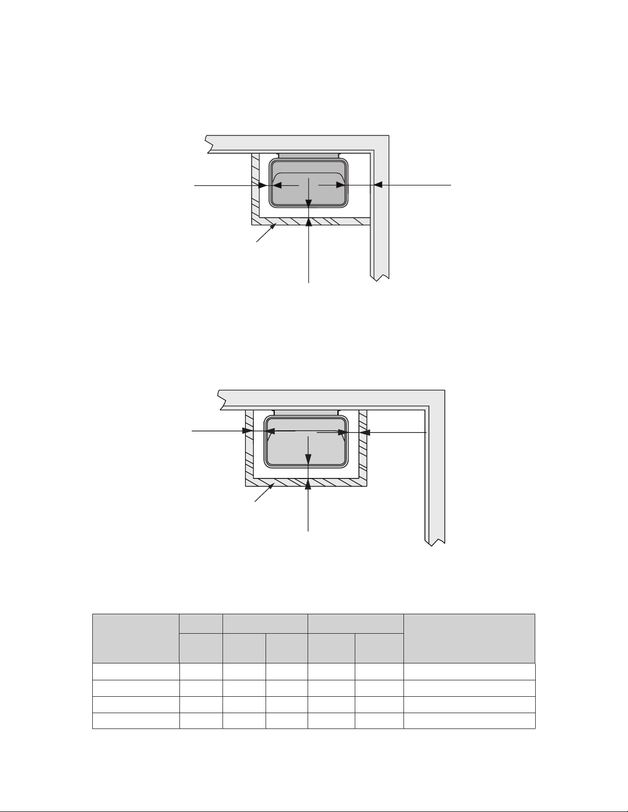
J. VENTILATION
Shouldbeprovidedbylowerventclose
to heater, 4” from oor, and upper
vent on opposite wall (if possible) 6”
from ceiling or as low as 24” from
oor. Vents should be adjustable and
should allow air to change 5 times per
hour. Sauna shall be provided with
intended ventilations as required per
the local code authorities.
K. LIGHT
Should be wall-mounted, vapor proof
type, with rough-in box mounted
ush with inside paneling. It should
mount 6’ 6” from the oor, not directly
over sauna heater, and not over upper
benches; light bulb should not exceed
75 watts.
L. ACCESSORIES
Bucket, dipper and thermometer
are essential. Thermometer should
be placed over the sauna heater, 6”
from ceiling, for correct temperature
reading. Other accessories such as
hygrometer, sand timer, brushes, etc.
are available.
M. MAINTENANCE INSTRUCTIONS
Are included at the end of this manual.
N. WARNING SIGNS
Are furnished with sauna heater. The
metal “CAUTION” sign should be
fastened to wall, close to heater, in a
visible place. The metal “Warning”
sign should be fastened outside, to
the sauna room door.
WARNINGS!
* Do not smoke, use alcohol, or exercise
in the sauna!
* Do not exceed 30-minutes in the sauna
at one time, as excessive exposure can be
harmful to health. The sauna should not
be used as an endurance test!
* Persons with poor health should consult
their physicians before using the sauna!
* Avoid re, do not place any combustible
material over the sauna heater (towels,
bathing suits, wooden bucket or dipper)!
* Use only clean water on the stones -
do not use pool or spa water, as chlorine
gas can be produced and the heating
elements can be damaged!
* Hyperthermia occurs when the internal
temperature of the body reaches a
level several degrees above the normal
body temperatures of 98.6°F (37°C). The
symptoms of hyperthermia include an
increase in the internal temperature of
the body, dizziness, lethargy, drowsiness,
and fainting.
*The effects of hyperthermia include:
A) Failure to perceive heat
B) Failure to recognize the need to exit
the room
C) Unawareness of impending hazard
D) Fetal damage in pregnant women
E) Physical inability to exit the room
F) Unconsciousness
* Warning - the use of alcohol, drugs
or medication is capable of greatly
increasing the risk of fatal hyperthermia!