Hotstart HOTflow User manual

BEFORE YOU INSTALL
HOTow®engine heaters feature an integrated pump that circulates warm coolant throughout the entire engine at uniform
temperatures. Constant circulation of the coolant eliminates hot spots that can deteriorate heater hoses, harm engine seals
and diminish coolant life. However, initial installation of the heating system is critical; even seemingly minor adjustments to port
location, hose routing or heater positioning may help ensure your HOTow®CSM heater preheats your engine effectively.
DANGER
!
Personal injury: This product generates heat during operation. Operation of
a heating system with closed isolation valves could result in high pressure and
serious injury. It is the responsibility of the installer and operator to ensure that no
unsafe condition can result from the generation of pressure. In EU countries, PED
(97/23/EC) compliant pressure relief may be required (125 psi maximum).
Hazardous voltage: Before wiring, servicing or cleaning the heating system,
turn off the power and follow your organization’s lockout and tagout procedure.
Failure to do so could allow others to turn on the power unexpectedly, resulting in
harmful or fatal electrical shock.
CAUTION
!
Electrical hazard: Power source must be properly grounded and in accordance
with national and local electrical codes. A user-supplied circuit breaker (rated at
the appropriate amperage) is required for use in the main power feed line. Do not
connect heater prior to installation.
NOTICE
Read instructions carefully: The Hotstart warranty does not cover any damage
that a heating system may sustain from improper installation, improper operation,
improper specication or corrosion. Before installing your heater, be sure you have
the right heating system for your application. Carefully read all instructions before
installing and energizing your heater. The safety of any system incorporating
this heater is the responsibility of the assembler. The safe and proper use of this
heater is dependent upon the installer following sound engineering practices.
If the equipment is used in a manner not specied by the manufacturer, the
protection provided by the equipment may be impaired. All applicable electrical
safety standards dened by local jurisdictions must be followed. (Reference EU
directive 2006/95/EC in EU countries.)
INSTALLATION INSTRUCTIONS
HOTow®HEATER
CSM MODEL EURO
| page 1
installation instructions
Hotow®csm Heater
customer service:509.536.8660
installation and operation.
Hotstart Manufacturing, Inc. is the owner of
all trademarks and copyrightable material
contained herein; all rights are reserved;
no form of reproduction is authorized
without prior written consent from Hotstart
Manufacturing, Inc.
Original Instructions216229-010 rev3
A. Discharge port
B. Pump/motor
C. Mounting base
D. Element assembly
E. Thermostat
(in element assembly)
F. Customer control
wiring entrance
G. Power in wiring
entrance
H. Suction port
IOM216229-010 rev3
C
C
A B
DE
FG H
Corporate & Manufacturing
Headquarters
5723 E. Alki Ave.
Spokane, WA 99212 USA
509.536.8660
Oil & Gas Ofce
21732 Provincial Blvd.
Suite 170
Katy, TX 77450 USA
281.600.3700
Railroad Ofce
8915 Broadway
Merrillville, IN 46410 USA
219.648.2448
Europe Ofce
Hotstart Europe GmbH
Hansestraße 79
51149 Köln, Germany
+49.2203.98137.30
Asia Pacic Ofce
Hotstart Asia Pacic Ltd.
2-27-15-4F Honkomagome
Bunkyo-ku, Tokyo
113-0021, Japan
+81.3.6902.0551
C
C
A B
DE
FG H
Figure 1. Typical CSM Euro model (above)
and side view (below). Style and conguration
may vary.

INSTALLING THE HEATER
PREPARE COOLANT SYSTEM
1. Drain and ush cooling system to remove any debris
present in the engine’s cooling system.
SELECT PORTS
2. Select return port. The return port will allow heated
coolant to return to the engine. See Fig 2 on following
page. The return port should be located:
• away from the engine thermostat
• toward the rear (ywheel) of the engine
• away from the supply port
• on the same side of the engine as the intended
heater mounting location
3. Select supply port. The supply port will allow coolant
to ow from the engine to the heater. See Fig 2 on
following page. The supply port should be located:
• toward the front (radiator) of the engine
• at the lowest point of the engine’s water jacket
• away from the return port
NOTE: For V-type engines, it is acceptable to
select a supply port on the opposite side
of the engine as long as the supply hose is
routed properly. See PLUMB HEATER.
SELECT HOSE, FITTINGS & VALVES
4. Select ttings. CSM minimum port size tting:
• 20 mm (3/4 inch NPT)
5. Select hoses. CSM minimum hose inner diameter:
• 25 mm (1 inch)
NOTE: Select hoses rated for 121 °C (250 °F) and
690 kPa (100 psi) minimum.
6. Select optional, user-supplied isolation valves.
NOTE: Hotstart recommends installing valves to
isolate the heating system in case of service.
To minimize ow restriction, select full-ow
(full-port) ball isolation valves.
MOUNT HEATER
NOTICE
Vibration damage: Do not mount
heater directly to engine. Engine
vibration will damage heater. If the
heater is installed with rigid pipe,
connect exible hose to inlet and
outlet to isolate from vibration.
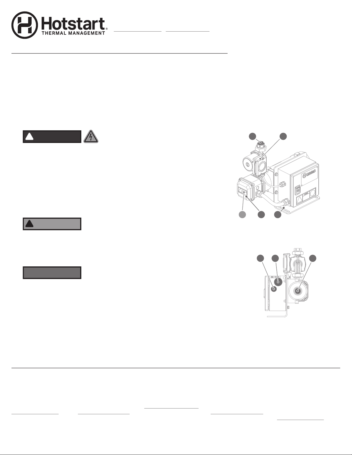
Heater orientation: CSM units must be installed with
discharge port pointing directly upward. See Fig 2 on
following page. Do not mount at an angle. An incorrectly
oriented heater may cause heater failure.
7. Select a heater mounting position. The heater should
be located:
• low enough to allow the return hose to continuously
rise to the return port
• on the same side of the engine as the return port
• in a position to ensure the discharge port points
directly upward
• in a location that allows a minimum of 43 cm
(17 inches) clearance for heating element removal
PLUMB HEATER
NOTICE
High points: Do not allow high
points along heater plumbing.
High points will restrict coolant
ow and damage heater. To avoid
high points, it may be necessary
to change hose routing or lower
heater mounting location.
Dips and bends: Do not allow dips
or bends along heater plumbing.
Dips or bends will allow air pockets
to form, restricting coolant ow
and damaging heater.
90° Fittings: Elbows (90° ttings) along heater plumbing
may restrict ow and damage heater. To minimize ow
restriction, Hotstart recommends sweeping bends or 45°
ttings in place of 90° ttings.
8. Install isolation valves to port ttings.
9. Route and install return hose. The return hose should
continuously rise from the heater to the return port.
10. Route and install supply hose. The supply hose
should continuously descend from the supply port
to the heater.
| page 2
installation instructions
Hotow®csm Heater

REFILL COOLANT
NOTICE
Heater damage: When mixing coolant, only use deionized
or distilled water and low-silicate antifreeze. Refer to your
engine’s manufacturer recommendations. Do not exceed
60% antifreeze to 40% water ratio. Never add unmixed
water and antifreeze to an engine. Do not add anti-leak or
other coolant additives.
11. Mix coolant according to your engine manufacturer’s
recommendations. Rell cooling system with coolant.
NOTE: Hotstart recommends using a 50% deionized
or distilled water to 50% low-silicate
antifreeze mixture.
12. Start engine. Allow engine to run until engine
thermostat opens, purging air from cooling system.
NOTICE! Engine must be run to eliminate air from
heating system before energizing heater.
13. When engine has reached operating temperature,
shut engine off and check for coolant leaks.
14. Allow engine to cool. Check coolant level and top off
as needed.
WIRE HEATER
15. Connect heater to an appropriately rated power source.
NOTICE! Terminations in all enclosures require that
wire be rated at a minimum of 60 °C. Selected wire
must be sized in accordance with heater amperage.
16. Connect user-supplied 24 V DC control signal wire
(typically to ignition system). NOTICE! The heating
system must be activated only while the engine is not in
operation. To enable automatic shutdown, the heating
system requires a connected 24 V DC signal.
| page 3
installation instructions
Hotow®csm Heater
Figure 2. Example CSM installation (Style B shown). The return hose continuously
rises to the engine and supply hose continuously descends to the heater; the hoses
have no dips, bends or high points. The heater is isolated from engine vibration and
is mounted in the proper orientation. RETURN PORT
• Select a return port away from the engine thermostat.
• Select a return port toward the rear of the engine.
• Select a return port away from the supply port.
SUPPLY PORT
• Select a supply port low on the engine.
• Select a supply port toward the front of
the engine.
• Select a supply port away from the
return port.
HEATER MOUNTING
• Mount the heater in the proper orientation. Ensure
discharge port is pointing directly upward.
• Mount the heater to a vibration-isolated surface.
• Mount the heater on the same side as the return port.
Figure 3.
Typical CSM
Euro model,
showing
electrical
connections.
MAIN
POWER TB1
Line 1 L1
Line 2 L2
Line 3 L3
Neutral N
Ground ground terminal
ELEMENT SIGNAL K1 TORQUE
Element On 13 1.2 N·m
(11 lb·in)
14
CUST. CONTROL &
SYSTEM ON K2
Run Signal (+) A1+
Run Signal (-) A2-
System On (NO) 24
21
System On (NC) 22
21

TROUBLESHOOTING
To ensure coolant is owing, check the outlet temperature.
If the coolant temperature along the return hose exceeds
60 °C (140 °F) or the pump produces a loud, rattling sound
during operation, it may indicate:
• Air pockets are restricting ow. Air may collect due
to loops in hose, routing hose over the top of the
engine, excessive hose lengths, or kinks. Reroute
hoses or change port locations.
• Contaminants in the coolant are restricting ow. Flush
coolant system and rell.
MAINTENANCE & PARTS
CAUTION
!
Electrical hazard: Before wiring, servicing or cleaning
the heating system, turn off the power and follow your
organization’s lockout and tagout procedure. Failure to do
so could allow others to turn on the power unexpectedly,
resulting in harmful or fatal electrical shock.
Personal injury: If equipped with isolation valves, ensure
valves are open before energizing heater. Obstructed ow
may result in an unexpected release of heated coolant,
potentially causing serious injury.
PREVENTATIVE MAINTENANCE
Annually:
• Check and replace cracked or weakened hoses.
• Check electrical wiring for wear and excessive heat.
• Remove element and clean element and tank.
Every three years or 25,000 hours of operation:
• Replace control thermostat.
• Replace contactor.
THERMOSTAT & ELEMENT
To replace the thermostat or clean tank: (See Fig. 5)
| page 4
installation instructions
Hotow®csm Heater
1. Disconnect heater from power
source. Allow heating system
to cool.
2. Remove element assembly
enclosure cover:
hIf cleaning tank, unscrew
wiring enclosure screws to
remove wiring enclosure.
Unscrew element plate screws.
Remove plate and element
from tank.
hIf replacing thermostat,
disconnect terminals from
thermostat sensing unit spade
connectors.
3. Replace thermostat unit or
clean tank.
hIf replacing thermostat,
remove the two thermostat
mounting screws (T25) and
thermostat clip. Remove
thermostat. Ensure thermostat
recess is clean and free of
debris. Install new thermostat
in recess and secure using
new thermostat clip. Reinstall
and tighten clip screws.
hIf cleaning tank, ensure
element O-ring is in place.
4. Reconnect electrical
connections. Reattach
enclosure, element plate,
O-rings and enclosure cover.
5. Reconnect heater to power
source.
USER
SIGNAL
MAIN
ELEMENT ON
A
P
O
N
D
B
C
M
L
K
J
I
H
E
F
G
Figure 5. Cleaning element or
replacing thermostat (below) and
thermostat/element wiring detail
(right). Wiring and conguration
may vary.
Figure 4. Typical CSM Euro wiring schematic. See label attached to
control box lid for your specic wiring schematic.
A. Element O-ring
B. Enclosure gasket
C. Wiring entrance
D. Wiring conduit
E. Enclosure lid gasket
F. Enclosure cover
G. Enclosure screws
H. Thermostat screws
I. Thermostat clip
J. Thermostat
K. Enclosure screws
L. Retaining Ring
M. Wiring enclosure
N. Element plate screws
O. Element assembly
P. Tank
Other Hotstart Heater manuals
Popular Heater manuals by other brands

Toyotomi
Toyotomi zibro RS - 24 operating manual

Phormalab
Phormalab hotdoor HCA01 Assembly instructions

NuTone
NuTone 120 user guide

SUNTEC
SUNTEC KLIMATRONIC HEAT SAFE 1500 instruction manual

Empire Heating Systems
Empire Heating Systems BF-10W-1 installation instructions

IntelliHeat
IntelliHeat iSense ISEN-0750 Installation and operating instructions

Qlima
Qlima R7224S C operating manual

Flandria
Flandria BodyHeat Series Installation maintenance and operating instructions

HAEGER
HAEGER iHeat Plus HE-20T.002B User instructions

Barton
Barton 96968 Owner's manual and safety instructions

Sunshower
Sunshower COMBI WHITE user manual

Uberhaus
Uberhaus HPS-C-GH Operator's manual