Hotsy 1065SS Service manual

9.807-621.0
SERIAL NUMBER:
DATE PURCHASED:
FOR SALES AND SERVICE, PLEASE CONTACT:
®
c
L
I
S
T
E
D
®
OPERATING INSTRUCTIONS AND PARTS MANUAL
Thank you for purchasing a Hotsy Pressure Washer. This manual covers the operation and mainte-
nance of your pressure washer. All information in this manual is based on the latest product informa-
tion available at the time of printing. Hotsy, Inc. reserves the right to make changes at any time with-
out incurring any obligation.
Read instructions carefully before attempting to assemble, install, operate or service this pressure
washer. Failure to comply with instructions could result in personal injury and/or property damage!
MODELS 965SS, 1065SS,
1065SSE, 1075SSE

HOTSY 965SS-1075SS • 9.807-621.0 • Rev. 09/18
OPERATOR’S MANUAL
PRESSURE WASHER
2
965SS SPECIFICATIONS
Pump Volume At Pump Head: 3.0 GPM/180 GPH
Pump Pressure At Pump Head: 3000 PSI
Burner Type: Fuel Oil Fired, 248,000 BTU/Hr.
Burner Fuel Pressure: 205 PSI Max.
Machine Displacement: 270cc
Exhaust Stack Size: 8"
Machine Dimensions: Length=47",
Width=31", Height=47"
1065SS SPECIFICATIONS
Pump Volume At Pump Head: 3.5 GPM/210 GPH
Pump Pressure At Pump Head: 3000 PSI
Burner Type: Fuel Oil Fired, 309,900 BTU/Hr.
Burner Fuel Pressure: 205 PSI Max.
Machine Displacement: 337cc
Exhaust Stack Size: 8"
Machine Dimensions: Length=47",
Width=31", Height=49"
1065SSE SPECIFICATIONS
Pump Volume At Pump Head: 3.5 GPM/210 GPH
Pump Pressure At Pump Head: 3000 PSI
Burner Type: Fuel Oil Fired, 309,900 BTU/Hr.
Burner Fuel Pressure: 205 PSI Max.
Machine Displacement: 389cc Electric Start
Exhaust Stack Size: 8"
Machine Dimensions: Length=47",
Width=31", Height=49"
1075SSE SPECIFICATIONS
Pump Volume At Pump Head: 3.8 GPM/228 GPH
Pump Pressure At Pump Head: 3500 PSI
Burner Type: Fuel Oil Fired, 309,900 BTU/Hr.
Burner Fuel Pressure: 205 PSI Max.
Machine Displacement: 389cc Electric Start
Exhaust Stack Size: 8"
Machine Dimensions: Length=47",
Width=31", Height=49"

3
CONTENTS
HOTSY 965SS-1075SS • 9.807-621.0 • Rev. 09/18
Model Number ______________________________
Serial Number ______________________________
Date of Purchase ____________________________
The model and serial numbers will be found on a decal attached
to the pressure washer. You should record both serial number and
date of purchase and keep in a safe place for future reference.
Important Safety Information 5-6
Component Identication 7
Assembly Instructions 8-9
Installation Instructions 10
Operation Instructions 11-12
General Cleaning Techniques & Storage 13
Maintenance 14
Troubleshooting 15-17
Exploded Views & Parts List 18-20
Control Panel Assembly & Parts List 21
Fuel Tank Assembly & Parts List 22
Hose, Spray Gun & Wand Assembly & Parts List 22
Burner Assembly & Parts List 23
Burner Exploded View and Parts List 24-25
Pump Assembly & Parts List - 965SS 26
Pump Assembly & Parts List, 1065SS, 1065SSE, 1075SSE 27
Coil Outlet Assembly & Parts List
965SS, 1065SS, 1065SSE, 1075SSE 28
Coil Inlet Parts Exploded View and Parts List 29
HS.3 Pump Exploded View and Parts List 30-31
HG.1 Pump Exploded View and Parts List 32-33
Unloader Exploded View and Parts List 34
VBT Unloader Exploded View and Parts List 35
Wiring Diagrams 36-37

HOTSY 965SS-1075SS • 9.807-621.0 • Rev. 09/18
OPERATOR’S MANUAL
PRESSURE WASHER
4
INTRODUCTION & IMPORTANT SAFETY INFORMATION
Thank you for purchasing this Pressure Washer.
We reserve the right to make changes at any time
without incurring any obligation.
Owner/User Responsibility:
The owner and/or user must have an understanding of
the manufacturer’s operating instructions and warnings
before using this pressure washer. Warning information
should be emphasized and understood. If the operator
is not uent in English, the manufacturer’s instruc-
tions and warnings shall be read to and discussed
with the operator in the operator’s native language by
the purchaser/owner, making sure that the operator
comprehends its contents.
Owner and/or user must study and maintain for future
reference the manufacturers’ instructions.
The operator must know how to stop the machine
quickly and understand the operation of all controls.
Never permit anyone to operate the engine without
proper instructions.
SAVE THESE INSTRUCTIONS
This manual should be considered a permanent
part of the machine and should remain with it if
machine is resold.
When ordering parts, please specify model and
serial number. Use only identical replacement parts.
This machine is to be used only by trained operators.
IMPORTANT SAFETY
INFORMATION
READ OPERATOR’S
MANUAL THOROUGHLY
PRIOR TO USE.
WARNING: To reduce the risk
of injury, read operating in-
structions carefully before us-
ing.
1.
Read the owner's manual
thoroughly. Failure to follow
instructions could cause
malfunction of the machine
and result in death, serious
bodily injury and/or prop-
erty damage.
2. Know how to stop the machine and bleed pressure
quickly. Be thoroughly familiar with the controls.
3. Stay alert — watch what you are doing.
WARNING
KEEP WATER
SPRAY AWAY FROM
ELECTRICAL WIRING.
WARNING: Keep wand, hose, and
water spray away from electric wir-
ing or fatal electric shock may result.
4. All installations must comply
with local codes. Contact
your electrician, plumber,
utility company or the selling
distributor for specic details.
WARNING
EAR PROTECTION
MUST BE WORN
WARNING: This machine ex-
ceeds 85 db appropriate ear
protection must be worn.
WARNING
USE PROTECTIVE
EYE WEAR
AND CLOTHING
WHEN OPERATING
THIS EQUIPMENT.
WARNING: High pressure spray
can cause paint chips or other
particles to become airborne
and y at high speeds. To avoid
personal injury, eye, hand and
foot safety devices must be
worn.
5. Eye, hand, and foot protection
must be worn when using this
equipment.
6. Keep operating area clear of all persons.
RISK OF EXPLOSION:
OPERATE ONLY WHERE
OPEN FLAME OR TORCH
IS PERMITTED
WARNING
WARNING: Flammable liquids
can create fumes which can ig-
nite, causing property damage
or severe injury.
WARNING: Risk of explosion —
Operate only where open ame
or torch is permitted.
RISK OF FIRE.
DO NOT ADD FUEL
WHEN OPERATING
MACHINE.
WARNING
WARNING: Risk of re — Do not
add fuel when the product is
operating or still hot.
WARNING: Do not use gasoline
crankcase draining or oil con-
taining gasoline, solvents or
alcohol. Doing so will result in
re and/or explosion.
WARNING: Risk of re — Do not
Spray ammable liquids.

HOTSY 965SS-1075SS • 9.807-621.0 • Rev. 09/18
5
PRESSURE WASHER
OPERATOR’S MANUAL
HOT DISCHARGE FLUID:
DO NOT TOUCH OR
DIRECT DISCHARGE
STREAM AT PERSONS.
CAUTION: Hot discharge uid.
Do not touch or direct dis-
charge stream at persons.
WARNING: This machine pro-
duces hot water and must have
insulated components attached
to protect the operator.
13. To reduce the risk of injury, close supervision is
necessary when a machine is used near children.
Do not allow children to operate the pressure
washer. This machine must be attended during
operation.
TRIGGER GUN KICKS
BACK - HOLD WITH
BOTH HANDS
WARNING
WARNING: Grip cleaning wand
securely with both hands be-
fore starting. Failure to do this
could result in injury from a
whipping wand.
14. Never make adjustments on
machine while in operation.
15. Be certain all quick coupler ttings are secured
before using pressure washer.
RISK OF INJECTION
OR SEVERE INJURY
TO PERSONS. KEEP
CLEAR OF NOZZLE.
WARNING
WARNING: High pressure de-
veloped by these machines will
cause personal injury or equip-
ment damage. Keep clear of
nozzle. Use caution when oper-
ating. Do not direct discharge
stream at people, or severe in-
jury or death will result.
WARNING
PROTECT FROM
FREEZING
WARNING: Protect machine
from freezing.
16. To keep machine in best
operating conditions, it is
important you protect machine
from freezing. Failure to protect
machine from freezing
could cause malfunction of the
machine and result in death,
serious bodily injury, and/or property damage. Fol-
low storage instructions specied in this manual.
17. Inlet water must be clean fresh water and no hotter
then 90°F.
IMPORTANT SAFETY INFORMATION
WARNING: This product contains chemicals known
to the state of California to cause cancer and birth
defects or other reproductive harm. Operation of
this equipment may create sparks that can start
res around dry vegetation. A spark arrestor may
be required. The operator should contact: Local
re agencies for laws or regulations relating to re
prevention requirements
.
7. Allow engine to cool for 1-2 minutes before refuel-
ing. If any fuel is spilled, make sure the area is dry
before testing the spark plug or starting the engine.
(Fire and/or explosion may occur if this is not done.)
Gasoline engines on mobile or portable equipment
shall be refueled:
a. outdoors;
b. with the engine on the equipment stopped;
c. with no source of ignition within 10 feet of
the dispensing point; and
d. with an allowance made for expansion of the
fuel should the equipment be exposed to a
higher ambient temperature.
In an overlling situation, additional precautions are
necessary to ensure that the situation is handled
in a safe manner.
WARNING: Risk of injury. Disconnect battery
ground terminal before servicing.
8. When in use , do not place machine near ammable
objects as the engine is hot.
9. Oil burning appliances shall be installed only in
locations where combustible dusts and ammable
gases or vapors are not present. Do not store or
use gasoline near this machine.
10. Use No. 1 or No. 2 heating oil (ASTM D306) only.
NEVER use gasoline in your fuel oil tank. Gasoline
is more combustible than fuel oil and could result
in a serious explosion. NEVER use crankcase or
waste oil in your burner. Fuel unit malfunction could
result from contamination.
11. Do not confuse gasoline and fuel oil tanks. Keep
proper fuel in proper tank.
WARNING
RISK OF INJURY.
HOT SURFACES
CAN CAUSE BURNS
WARNING: Risk of injury. Hot
surfaces can cause burns. Use
only designated gripping areas
of spray gun and wand. Do not
place hands or feet on non-in-
sulated areas of the pressure
washer.
12. Transport/Repair with fuel tank EMPTY or with fuel
shut-off valve OFF.

HOTSY 965SS-1075SS • 9.807-621.0 • Rev. 09/18
OPERATOR’S MANUAL
PRESSURE WASHER
6
IMPORTANT SAFETY INFORMATION
WARNING
RISK OF
ASPHYXIATION: USE
THIS PRODUCT ONLY
IN A WELL
VENTILATED AREA.
WARNING: Risk of asphyxiation.
Use this product only in a well
ventilated area.
18. Avoid installing machines in
small areas or near exhaust
fans. Adequate oxygen is
needed for combustion or
dangerous carbon monoxide
will result.
19. Manufacturer will not be liable for any changes
made to our standard machines or any compo-
nents not purchased from us.
20. The best insurance against an accident is precau-
tion and knowledge of the machine.
WARNING
RISK OF INJURY
FROM FALLS WHEN
USING LADDER.
WARNING: Be extremely careful
when using a ladder, scaffold-
ing or any other relatively un-
stable location. The cleaning
area should have adequate
slopes and drainage to reduce
the possibility of a fall due to
slippery surfaces
.
21. Do not allow acids, caustic or abrasive uids to
pass through the pump.
22. Never run pump dry or leave spray gun closed
longer than 1-2 minutes.
23. Machines with shut-off spray gun should not be
operated with the spray gun in the off position for
extensive periods of time as this may cause dam-
age to the pump.
24. Protect discharge hose from vehicle trafc and
sharp objects. Inspect condition of high pressure
hose before using or bodily injury may result.
25. Before disconnecting discharge hose from water
outlet, turn burner off and open spray gun to al-
low water to cool below 100° before stopping the
machine. Then open the spray gun to relieve pres-
sure. Failure to properly cool down or maintain the
heating coil may result in a steam explosion.
26. Do not overreach or stand on unstable support.
Keep good footing and balance at all times.
27. Do not operate this machine when fatigued or
under the inuence of alcohol, prescription medi-
cations, or drugs.
28. In oil burning models, use only kerosene, No. 1
home heating fuel, or diesel. If diesel is used, add
a soot remover to every tankful.
Follow the maintenance instructions
specied in the manual.

HOTSY 965SS-1075SS • 9.807-621.0 • Rev. 09/18
7
PRESSURE WASHER
OPERATOR’S MANUAL
COMPONENT IDENTIFICATION
Pump — Delivers a specic gpm to the high pressure
nozzle which develops pressure.
Spray Gun — Controls the application of water and
detergent onto cleaning surface with trigger device.
Includes safety latch.
Detergent Injector — Allows you to siphon and mix
detergents.
Wand — Must be connected to the spray gun.
High Pressure Hose — Connect one end to water
pump high pressure discharge nipple and the other
end to spray gun.
Unloader Valve — Safety device which, when the
spray gun closes, redirects ow of water.
Note:If trigger on spray gun is released for more
than 2 minutes, water may leak from the pump
protector. Warm water will discharge from pump
protector onto oor. This system prevents internal
pump damage.
Pump
Unloader
Valve
Detergent
Injector
Spray
Gun
High
Pressure Hose
Wand
Burner
Exhaust
Coil Outlet
Hose
Hanger
Engine
High
Pressure
Nozzle

HOTSY 965SS-1075SS • 9.807-621.0 • Rev. 09/18
OPERATOR’S MANUAL
PRESSURE WASHER
8
ASSEMBLY INSTRUCTIONS
Unpacking
Unpack carefully. Wear safety glasses or goggles while
unpacking, assembling, or operating pressure washer.
If there are missing components or hidden damage,
immediately contact carrier concerning discrepancies.
1. Cut strapping band from pressure washer and pallet.
2. Remove pressure washer from pallet.
Parts Included
• Pressure Washer
• Pressure Hose
• Wand
• Operating Instructions and Parts Manual
• Gasoline Engine Manual
• Parts Bag Containing:
Pressure Nozzles (3 Ea.)
Trigger Gun
Battery Terminals (2 Ea.)
Tools Required
• 8" Adjustable Wrench
• Teon Tape
• Flat Blade Screwdriver
Pressure Hose, Trigger Gun and Wand
1. When assembling, use teon tape on all threaded
plumbing connections to prevent leakage.
2. Install the pressure hose on the pressure washer as
shown in Figure 1.
3. Assemble wand components as shown in Figure 2.
NOTE: The pressure nozzle is not to be installed at
this time.
4. Make sure all plumbing connections are tight.
Battery
WARNING: Wear eye, hand and skin protection when
handling or connecting battery.
WARNING: Batteries generate explosive gases during
normal battery operation.
WARNING: DO NOT expose the battery to ame or
sparks as these gases may ignite.
WARNING: Battery uid is highly acidic. If battery
uid contacts skin or clothing, wash immediately
with soap and water. If battery uid enters eye, im-
mediately ood eye with running cold water for at
least 15 minutes and get immediate medical attention.
1. Electric Start Machines Only: Place battery in bat-
tery box (battery not included). Use a standard 12 volt
automotive battery. Select a battery similar to the one
in Figure 3 for proper t and installation.
2. Install the battery terminals as shown in
Figure 2 - Wand Assembly
Trigger Gun
Quick
Disconnect
Quick Disconnect
Wand
Quick
Disconnect Plug
Pressure
Hose
Figure 3 - Battery Dimensions
6-3/4"
Max
10-1/2"
Max
8-3/4"
Max
Relief Valve
Figure 1 - Pressure Hose Installation
Pressure
Hose

HOTSY 965SS-1075SS • 9.807-621.0 • Rev. 09/18
9
PRESSURE WASHER
OPERATOR’S MANUAL
Figure 4.
3. To reduce the possibility of sparking attach the wires
to the battery in the following order. Refer to Figure
4. First attach the red wire from the voltage regulator
and the red wire from the control box to the positive
“+" terminal of battery. Next, attach the black wire
from the voltage regulator and the black wire from the
control box to the negative “-" terminal of the battery.
To disconnect the battery remove the wires in the
opposite order as installed. Install battery box cover
and fasten in place.
Figure 4 - Battery Installations/Connections
Box Strap
Battery
Box Lid
Red Wire From
Control Box
Black Wire
From Voltage
Regulator
Red Wire From
Voltage Regulator
12 Volt
Battery
Battery
Terminal
Battery Box
Black Wire From
Control Box
ASSEMBLY & INSTALLATION INSTRUCTIONS
INSTALLATION
Responsibility
The owner and/or user must have an understanding
of the manufacturer’s operating instructions and warn-
ings before using this Hotsy pressure washer. Warning
information should be emphasized and understood.
If the operator is not uent in English, the manufac-
turer’s instructions and warnings shall be read to and
discussed with the operator in the operator’s native
language by the purchaser/owner, making sure that
the operator comprehends its contents.
Owner and/or user must study and maintain for future
reference the manufacturers’ instructions.
This manual should be considered a permanent part
of the machine and should remain with it if machine
is resold.
When ordering parts, please specify model and se-
rial number.
Getting Started
IMPORTANT: Proper initial installation of equipment
will assure more satisfactory performance, longer
service life, and lower maintenance cost.
IMPORTANT: The use of a backow preventer on
the water supply hose is recommended and may be
required by local code.
The pressure washer should be run on a level surface
and in a protected area where it is not readily inuenced
by outside forces such as strong winds, freezing
temperatures, rain, etc. The pressure washer should
be located to assure easy access for lling of uids,
adjustments and maintenance. Normal precautions
should be taken by the operator to prevent moisture
from reaching the pressure washer. It is recommended
that a partition be made between the wash area and the
pressure washer to prevent direct spray from the wand
from coming in contact with the pressure washer. Moisture
reaching the equipment will reduce the pressure washer’s
service life. All installations must comply with the local
codes covering such installations.
Venting
CAUTION: All venting must be in accordance with ap-
plicable federal and state laws, and local ordinances.
Consult local heating contractors
.
If the pressure washer is to be used in an enclosed area,
a ue must be installed to vent burner and engine exhaust
to the outside atmosphere. Be sure the ue is the same
size as the burner exhaust vent on the pressure washer.
See Component Identication for location. Poor draft
will cause the pressure washer to soot and not operate
properly. When selecting the location for installation,
beware of poorly ventilated locations or areas where
exhaust fans may cause an insufcient supply of oxygen.
Proper combustion can only be obtained when there is a
sufcient supply of oxygen available for the amount of fuel
being burned. If it is necessary to install the machine in a
poorly ventilated area, outside fresh air may have to be
piped to the burner and a fan installed to bring sufcient
air into the machine. Locate the pressure washer so
that the ue will be as straight as possible and protrude
through the roof at a proper height and location to provide
adequate draft. This oil red pressure washer must have
a draft regulator installed in the ue (available from most
heating contractors). A draft regulator will permit proper
upward ow of exhaust ue gases.
In addition, the pressure washer should never be operated
in an enclosed area where high ambient temperatures
exist. High ambient temperatures (above 100o F) can
cause engine oil failure and will greatly reduce the
engine’s performance.

HOTSY 965SS-1075SS • 9.807-621.0 • Rev. 09/18
OPERATOR’S MANUAL
PRESSURE WASHER
10
INSTALLATION INSTRUCTIONS
Gasoline Engine
The gasoline engine is preset for operation at altitudes
below 1000 feet above sea level. If operated at higher
altitudes, it may be necessary to install a high altitude
main jet in the carburetor. Contact a local authorized
engine sales and service center for details.
Pre-Operation Check
Pump Oil (SAE 30W non-detergent oil)
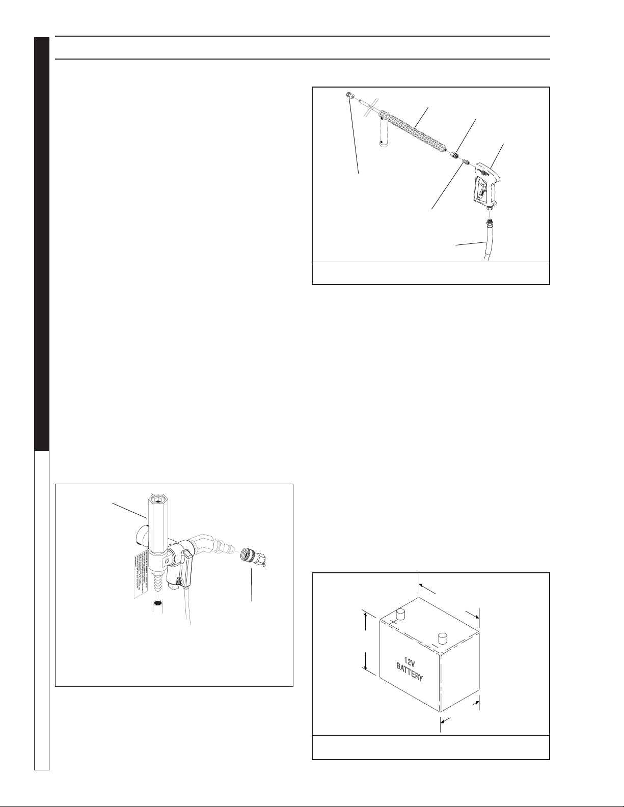
Cold Water Supply (6 gpm • 5/8" • 20 psi)
Hose, wand, nozzle (nozzle size per serial plate)
Water lter (intact, nonrestrictive)
Engine fuel (unleaded 86 or higher)
Engine oil (SAE 10W30)
Burner fuel (No. 1 or No. 2 home heating fuel or
diesel)
If the desired position cannot be obtained using only the
air shutter, lock the air shutter in as close a position as
can be obtained, then repeat the above procedure on the
air band setting.
CAUTION: If white smoke appears from burner
exhaust vent during start-up or operation, discontinue
use and readjust air bands.
NOTE: If a ue is installed, have a professional ser-
viceman adjust your burner for a #1 or #2 smoke spot
on the Bacharach scale.
Wayne Oil Burner
Burner Air Adjustment:
The oil burner on this machine is preset for operation at
altitudes below 500 feet. If operated at higher altitudes,
it may be necessary to adjust the air band for a #1 or
#2 smoke spot on the Bacharach scale.
To adjust, start machine and turn burner ON. Loosen
two locking screws found on the air band and close air
band until black smoke appears from burner exhaust
vent. Note air band position. Next, slowly open the air
band until white smoke just starts to appear. Turn air
band halfway back to the previously noted position.
Tighten locking screws.
• For higher altitudes, the air band opening may
need to be increased; for lower altitude, the air band
may need to be decreased.
• For higher humidity, the air band opening may need
to be increased; for lower relative humidity, the air band
may need to be decreased.
• For higher ambient temperatures the air band
opening may need to be increased; for lower ambient
temperatures, the air band opening may need to be
decreased.
Adjust to your operating location’s environment as-
needed for best smoke spot and performance compli-
ant with local, state, and federal regulations.
Fuel Pressure Adjustment:
To adjust fuel pressure, First install a pressure gage
into the port just after the pump fuel exit. Turn the ad-
justing screw (located at the regulator port) clockwise
to increase, and counterclockwise to decrease. Do not
exceed 205 psi or lower the pressure below 130 PSI,
when checked at the post-pump pressure port.
The fuel pressure may need to be adjusted due to
altitude. For every 500 ft altitude above sea level, the
boiling point of water goes down 1 °F. At high altitude
environments, this boiling point change may require
the heat input to be lowered so the water input does
not turn to steam earlier than at the factory settings
and activate the pressure sensors and pressure relief
equipment when the unit is operated and much higher
altitudes from factory settings or local dealer site set-
tings. Check with your dealer before making local site
fuel pressure adjustments.
Also, as ambient temperature changes seasonally, the
fuel temperature in the feed tank and air temperature
inlet can impact fuel ow. In more extreme tempera-
tures, this local-site adjustment may also require dif-
ferent fuel nozzles for fuel inlet temperatures that are
at seasonal extremes (higher or lower) in locations
where the temperature changes are beyond moder-
ate temperatures of between 40°F and 90°F. Colder
temperatures will make for a thicker ow and less ne
a fuel spray while hotter temperatures will make for a
thinner ow a more ne spray with the same nozzle.
Consider alternate nozzle congurations from the
baseline factory-supplied nozzle for operating in such
temperature extremes if performance is not meeting
needs with air band and fuel pressure settings alone.
NOTE: When changing fuel pump, a by-pass
plug must be installed in return line port or
fuel pump will not prime.

HOTSY 965SS-1075SS • 9.807-621.0 • Rev. 09/18
11
PRESSURE WASHER
OPERATOR’S MANUAL
OPERATION INSTRUCTIONS
Before Starting
1. Read all manuals provided with this pressure washer.
Become familiar with location and function of all
operating and safety controls.
WARNING: Check hoses, ttings, wand, trigger gun
and fuel connections daily for signs of wear, cracks
and looseness, and replace as required.
2. Connect water supply hose to the garden hose con-
nector located on pump. The water faucet and supply
hose must be capable of providing a minimum of 3.5
gallons per minute (GPM).
3. Fill oil burner fuel tank. Use kerosene, #1 grade home
heating oil, #1 or #2 diesel fuel.
DO NOT USE GASO-
LINE, CRANKCASE OIL DRAININGS, OR WASTE OIL.
WARNING: DO NOT ll engine fuel tank while engine
is running or hot. Let engine cool before refueling or
spontaneous re may result. Fuel spillage or vapors
could ignite if engine is hot.
4. Fill the engine fuel tank. Do not overll, ll to the
bottom of ller neck only. Use lead free gasoline
minimum 86 octane. DO NOT use gasoline containing
more than 15% MTBE, 5% methanol or 10% ethanol.
Refer to the provided gasoline engine manual for
additional details.
5. Check pump and engine oil levels.
6. If detergents are to be used, only use detergents
intended for pressure washers. Follow instructions on
the detergent container.
IMPORTANT: Before installing pressure nozzle on
initial start-up, turn on the water supply and allow
water to run from the end of the wand until clear to
prevent the pressure nozzle from clogging.
IMPORTANT: If the pressure washer has not been
used for an extended period of time, remove the
pressure nozzle from the end of the wand and turn
on water supply. Allow water to run from the end of
the wand until clear.
7. Install the proper pressure nozzle for your cleaning
needs on the end of wand, refer to Figure 6.
IMPORTANT: The trigger gun provided with this pres-
sure washer is equipped with a manual trigger lock to
prevent accidental operation of the trigger gun. (Refer
to Figure 6.) The manual trigger lock should be used
whenever the trigger gun is not in use.
To Start
IMPORTANT: The water must be turned on before
starting. Running the pump dry will cause damage
and void warranty.
IMPORTANT: DO NOT allow the machine to run with
trigger of the trigger gun released for more than
2 minutes at any one time or damage to pump may
occur.
1. Turn ON water supply.
2. Hold wand rmly, release trigger of trigger gun.
3. Place engine ON/OFF switch in the ON position.
4. Open fuel shutoff valve (if so equipped). Move choke
lever to FULL CHOKE position, (choke may not be
needed on warm engine). Move throttle lever to HALF
THROTTLE position.
5. Pull the rope starter slowly until resistance is felt, then
pull briskly. Do not allow the rope starter to snap back
against the engine. Return it gently to prevent damage
to the starter.
6. When the engine starts, move choke lever until
engine runs smoothly. When engine warms, move
choke lever to NO CHOKE position. Move throttle
lever to FULL THROTTLE position.
IMPORTANT: To allow for proper battery charging,
the throttle control must be kept in the full throttle
position during operation.
NOTE: If engine fails to start, refer to Troubleshooting
Guide in this manual.
7. Squeeze trigger of trigger gun and allow air to purge
from system.
8.
If hot water is desired, adjust the thermostat to the
proper temperature and turn burner switch ON. The
burner will light immediately with a small puff of smoke.
You may need to initially adjust your burner for peak
performance. See Oil Burner section under Installa-
tion. When the trigger of the trigger gun is released or
when the thermostat temperature setting is reached,
the burner will automatically turn off.
To Clean
The detergent injector valve operates by reducing the
volume of water, thus a vacuum is achieved and detergent
is drawn into the system. DO NOT reduce the water
inlet ow so the pump cavities due to water starvation.
Operating a pump with insufcient water will damage
the pump seals.
1. Insert detergent inlet line into container of mixed
detergent.
Figure 6 - Nozzle Installation/Manual Trigger Lock
Manual
Trigger Lock
Pressure
Nozzle

HOTSY 965SS-1075SS • 9.807-621.0 • Rev. 09/18
OPERATOR’S MANUAL
PRESSURE WASHER
12
2. Completely open detergent control knob located
on the side of the detergent injector valve. Refer to
Figure 7.
3. Start the detergent suction by rotating the water
adjustment knob of the detergent injector valve.
Refer to Figure 7. Turning the knob counterclockwise
will pull detergent into the system. The ow may be
observed through the clear detergent line. Secure the
knob position with the knurled nut.
4. The side detergent control knob can now be adjusted
to meter the desired amount of detergent.
5. Wash from the bottom to the top, using side to side
motions. This washes away heavy dirt and allows the
detergent to soak as you work toward the top.
6. Do not wash at a 90o angle to the work (straight at
it). This will allow water to splash back at you and
reduces your cleaning power. Wash at a 30o to 60o
angle to the work. This will allow the water to splash
away from you and the water will wash the dirt away
faster and easier.
7. Use the width of the spray pattern to wash in a
wide path. Overlap spray paths for complete cover-
age washing from side to side, using slow, steady
motions.
8. The nozzle should be 12" to 24" from work, closer
for tough areas. Be careful on painted or delicate
surfaces, the pressure may damage surface if nozzle
is too close.
9. Small parts should be washed in a basket so the
pressure does not push them away. Larger, lightweight
parts should be clamped down so the pressure does
not push them away.
10. Turn the side detergent control knob clockwise (CW)
for detergent decrease. Wait for detergent to clear.
Always rinse with cold water after using detergent.
Rinse from the top to the bottom to prevent detergent
from dripping onto a rinsed area. For the best results,
contact your Hotsy dealer to help you select the best
detergent for your application.
To Stop
1. If detergents were used, draw clear water through the
detergent inlet line to purge detergent. Failure to do
so may clog detergent injector valve.
2. If burner was used, turn OFF burner switch and
allow pump to run cold water through coil for several
minutes.
3. Move throttle lever to idle position.
4. Turn engine ON/OFF switch to the OFF position.
5. Close fuel shutoff valve (if so equipped).
6. Turn water supply OFF.
7. Squeeze trigger of trigger gun to relieve system
pressure.
OPERATION INSTRUCTIONS
Figure 7 - Detergent Injector Valve
Water
Adjustment
Knob
Detergent On
(Counterclockwise)
Detergent
Control Knob
Detergent
Injector

HOTSY 965SS-1075SS • 9.807-621.0 • Rev. 09/18
13
PRESSURE WASHER
OPERATOR’S MANUAL
Pre-rinse cleaning surface with fresh water. Place deter-
gent suction tube directly into cleaning solution and apply
to surface at low pressure (for best results, limit your work
area to sections approximately 6 feet square and always
apply detergent from bottom to top). Allow detergent to
remain on surface 1-3 minutes. Do not allow detergent
to dry on surface. If surface appears to be drying, simply
wet down surface with fresh water. If needed, use brush
to remove stubborn dirt. Rinse at high pressure from top
to bottom in an even sweeping motion keeping the spray
nozzle approximately 1 foot from cleaning surface. Use
overlapping strokes as you clean and rinse any surface.
For best surface cleaning action spray at a slight angle.
Recommendations:
• Before cleaning any surface, an inconspicuous
area should be cleaned to test spray pattern and
distance for maximum cleaning results.
• If painted surfaces are peeling or chipping, use
extreme caution as pressure washer may remove
the loose paint from the surface.
• Keep the spray nozzle a safe distance from the
surface you plan to clean. High pressure wash a
small area, then check the surface for damage. If
no damage is found, continue to pressure washing.
CAUTION - Never use:
• Bleach, chlorine products and other corrosive
chemicals
• Liquids containing solvents (i.e., paint thinner,
gasoline, oils)
• Tri-sodium phosphate products
• Ammonia products
• Acid-based products
These chemicals will harm the machine and will damage
the surface being cleaned.
RINSING
It will take a few seconds for the detergent to clear.
Apply safety latch to spray gun. Select and install de-
sired high pressure nozzle. NOTE: You can also stop
detergent from owing by removing detergent siphon
tube from bottle.
STORAGE
DANGER: DO NOT store ammable liquids (gasoline,
diesel fuel, solvents, etc.) near pressure washer, or
in non-ventilated areas.
Protect from freezing by storing in a heated area, or by
ushing the system with antifreeze (use an automotive
engine antifreeze or windshield washer solvent to
antifreeze). To flush the system with antifreeze, the
following steps are to be followed:
1. Connect water supply hose to the garden hose con-
nector located on the pump. Turn on water supply.
2. Place the detergent inlet line into a container of
GENERAL CLEANING TECHNIQUES & STORAGE
antifreeze.
3. Hold wand rmly, release trigger of trigger gun.
4. Start engine. Place throttle lever in Full Throttle
position.
5. Squeeze trigger of trigger gun and allow water to
ow from the end of the wand. Watch for antifreeze
to be drawn through the detergent inlet line. Allow
the antifreeze to be drawn into the system for 5 to
10 seconds.
6. Release the trigger of the trigger gun and stop
engine.
7. Turn off water supply and disconnect water supply
hose from the pump.
8. Attach a short length of hose (approximately 3 feet
long) to the garden hose connector located on the
pump. Install a funnel in the other end of the hose as
shown in Figure 8.
9. Hold wand rmly, release the trigger of the trigger gun.
10. Start engine. Place throttle lever in the idle position.
11. Squeeze trigger on trigger gun.
12. Slowly pour antifreeze into the funnel. Continue to
add antifreeze until antifreeze ows from the end of
the wand.
13. Squeeze and release the trigger of the trigger gun
several times to antifreeze the unloader system.
14. Release the trigger of the trigger gun. Stop engine.
15. Squeeze the trigger of the trigger gun to relieve system
pressure.
For added protection, after anti freezing, disconnect the
pressure hose from the machine and remove the coil drain
plug (refer to Component Identication for location.)
After coil has drained, replace pressure hose and coil
drain plug. If the pressure washer is not to be used for
an extended length of time, it is recommended that the
system be ushed with antifreeze for rust protection.
Refer to the Gasoline Engine Manual for engine storage
information.
CHAUD!
Funnel
Garden Hose Connector
Figure 8 - Winterizing

HOTSY 965SS-1075SS • 9.807-621.0 • Rev. 09/18
OPERATOR’S MANUAL
PRESSURE WASHER
14
MAINTENANCE
WARNING: Unauthorized machine modication or
use of non-approved replacement parts may cause
personal injury and/or property damage and will void
the manufacturer warranty.
Pump
Lubrication: To lubricate pump, use 30W (non-detergent)
oil for pump crankcase. Crankcase must be lled to center
of red dot on oil gauge found on the side of the pump, refer
to Figure 9. During the break-in-period, make sure the
oil is changed after the rst 40 hours of operation. After
that, replace oil every 3 months or 500 hours of operation,
whichever comes rst.
Proper Pump Care:
• DO NOT pump acids.
• DO NOT allow pump to run dry.
• Winterize if storing in freezing temperatures, refer
to Storage for details.
• Use a water softener on the water system if known
to be high in mineral content.
• Use only high quality detergents and follow manu-
facturer's mix recommendations.
• Flush the system with clear water immediately
after using detergent solutions.
• Clean filter screen on detergent inlet line
periodically.
• Flush the pressure washer system with antifreeze
if storing for an extended period of time, refer to
Storage for details.
Gasoline Engine
Refer to the provided Gasoline Engine Manual for
recommended maintenance.
Oil Burner
Blower Motor: Inspect the motor brushes for wear every
250 hours of operation and replace when 1/8" to 1/4"
brush material remains. DO NOT allow the brushes to
wear out completely or motor damage will occur. Refer to
Burner Assembly. The motor bearings are permanently
lubricated and will not require any additional lubrication.
Unloader Valve/ Relief valve
WARNING: The unloader valve and relief valve on this
pressure washer has been factory set and sealed and
is a eld nonadjustable part. Tampering with the facto-
ry setting may cause personal injury and/or property
damage, and will void the manufacturer warranty. For
replacement refer to Pump Assembly.
Burner Fuel Filter
Drain any water which has accumulated in fuel lter
and clean or replace lter element as needed. Refer to
Burner Assembly.
Heating Coil
Coil Descaling: In hard water areas, scale buildup within
the heating coil will occur. Scale deposits will decrease
the water temperature rise and may eventually clog the
heating coil. Contact your local service center when
descaling is needed.
Coil Desooting: Poor grades of fuel oil or inadequate
combustion air will cause heavy soot buildup on the
outside surface of the heating coil. These deposits will
insulate the coil. This will restrict the air ow through the
coil, further aggravating the soot buildup. Contact your
local service center when desooting is needed.
Hour Meter
This hour meter will monitor the total hours of operation of
the pressure washer to signal when routine maintenance
is required.
Battery
Refer to battery manufacturer’s literature for
recommended maintenance.
Relief Valve
WARNING: The relief valve on this pressure washer
has been factory set and sealed and is a eld non-
adjustable part. Tampering with the factory setting
may cause personal injury and/or property damage,
and will void the manufacturer warranty. For replace-
ment parts refer to Coil Outlet Assembly.
If pressure from pump or thermal expansion should
exceed safe limits, the relief valve will open, allowing
high pressure to be discharged through hose to ground.
Caution: Inspect relief valve annually for any
obstruction.
Oil Fill/Dipstick
Oil Drain
Plug
Oil Sight
Glass
Figure 9 - Pump Lubrication

HOTSY 965SS-1075SS • 9.807-621.0 • Rev. 09/18
15
PRESSURE WASHER Troubleshooting Guide
TROUBLESHOOTING
SYMPTOM POSSIBLE CAUSES CORRECTIVE ACTION
GAS ENGINE WILL
NOT RUN.
Out of gas Replenish supply. Use only recommended
fuels. Refer to Before Starting under
Operation.
Fuel valve closed (if so equipped) Open valve.
Loose spark plug wire Reconnect.
Choke or throttle set incorrectly Refer to To Start under Operation.
Engine ON/OFF switch in OFF
position
Place engine ON/OFF switch in ON posi-
tion.
Low engine oil level Replenish supply. Engine will not start or
run if oil is low (on engines equipped with
low oil protection).
Refer to provided gasoline engine manual for additional troubleshooting.
PRESSURE
WASHER RUNS BUT
WON’T SPRAY.
Trigger of trigger gun released Squeeze trigger.
Water supply not turned on Open water supply valve.
Clogged pressure nozzle Clean pressure nozzle opening.
If water spray doesn’t show with in
10-15 seconds
Discontinue running the machine and
troubleshoot as damage to the pump will
occur if allowed to run.
LOW SPRAY
PRESSURE AT
PRESSURE
NOZZLE.
Inadequate water supply Fully open faucet. Check for kinked or dam-
aged hose. Use 3/4 inch minimum hose.
Check for debris clogging inlet screen.
Partially clogged or damaged pres-
sure nozzle
Clean or replace.
Air being drawn through detergent
inlet line
Rell detergent container. Ensure that pick-
up screen is fully immersed.
Detergent injector valve not set
correctly
Refer to To Clean for settings.
UNEVEN SPRAY
PATTERN.
Partially clogged or damaged pres-
sure nozzle
Clean or replace.
PRESSURE
WASHER WILL NOT
PRODUCE HOT
WATER.
Burner switch in OFF position Place switch in ON position.
Inadequate fuel supply Rell fuel tank. Use only recommended
fuels. Refer to Before Starting under Op-
eration.
Inadequate water supply Fully open faucet. Check for kinked or dam-
aged hose. Use 3/4 inch minimum hose.
Check for debris clogging inlet screen.
Trigger of trigger gun released Squeeze trigger. Water must be spraying for
burner to light.
Thermostat set too low Adjust thermostat to desired temperature.
Blown fuse Replace. Fuse is located in control box.
Engine is running too slow Move throttle lever to full throttle position.

HOTSY 965SS-1075SS • 9.807-621.0 • Rev. 09/18
PRESSURE WASHER Troubleshooting Guide
16
TROUBLESHOOTING
SYMPTOM POSSIBLE CAUSES CORRECTIVE ACTION
POOR OR NO
DETERGENT FLOW.
Inadequate detergent supply. Refill detergent container. Ensure that
pick-up screen is fully immersed. Open
detergent valve.
Detergent screen or hose clogged. Clean. Always start with a clean detergent
container.
Detergent injector valve not set
correctly.
Refer to To Clean for settings.
Clogged detergent injector check valve. Clean check valve at detergent injector inlet
POOR CLEANING. Improper detergent concentration or
mixing.
Mix detergent per manufacturer’s instruc-
tions. Ensure that powdered detergents are
fully dissolved.
Wrong detergent for the application. Select appropriate detergent.
Rinsing with hot water. A nal rinse with cold water will reduce
water spotting.
MACHINE
SMOKES
Improper fuel or water in fuel Drain tank and replace contaminated fuel.
Improper air adjustment Readjust air bands on burner assembly.
Low fuel pressure < 140 PSI Adjust fuel pump pressure to specica-
tions.
Weak fuel pump Check fuel pump pressure. Replace pump
if needed.
Fuel lter partially cogged Replace as needed.
Soot build up on coils Clean coils with soot remover.
Lime build
up in coils
Clean inside of coils using Landa's coil
cleaner.
Improper burner nozzle See combustion assembly breakdown.
Electrode is misaligned Realign electrodres to specs.
Fuel pressure is to high for clean burn
(Fuel PSI above 140 but less than 200)
Reduce fuel PSI / increase air and band
set for cleaner burn without max water
heat loss.
WATER
TEMPERATURE
TOO HOT
Incoming water to machine warm or hot Lower incoming water temperature.
Fuel pump pressure too high Lower fuel pressure.
Fuel pump defective Replace fuel pump.
Detergent line
sucking air
Tighten all clamps. Check detergent line
for holes.
Defective high limit switch Replace.
Incorrect fuel nozzle size See exploded view parts list for proper size.
Insufcient water supplied Check G.P.M. to machine.
Restricted water ow Check nozzle for obstruction, proper size.
A) SMOKES
WHILE UNIT IS
RUNNING
B) SMOKES AT
COLD-START
WHEN BURNER
IS OF
AB
AB
AB
AB
AB
AB
AB
AB
AB
B

HOTSY 965SS-1075SS • 9.807-621.0 • Rev. 09/18
17
PRESSURE WASHER Troubleshooting Guide
When ordering from your dealer, please provide the following:
Model Number: 965SS, 1060SS, 1065SS, 1065SSE, 1075SSE
Machine Serial Number: ________________________________
Component Part Number: ______________________________
Description: __________________________________________
IMPORTANT
If the pressure washer demonstrates other symptoms or the corrective actions
listed do not correct the problem, contact the local authorized Hotsy Service
Center. The Hotsy Service Center can be identied by visiting www.hotsy.com.
TROUBLESHOOTING

HOTSY 965SS-1075SS • 9.807-621.0 • Rev. 09/18
OPERATOR’S MANUAL
PRESSURE WASHER
18
EXPLODED VIEW - LEFT SIDE
“Thisproduct contains chemicals known to the State of
Californiato cause cancer and birth defects or other
reproductiveharm. Operation of This Equipment May
CreateSparks That Can Start Fires Around Dry Vegetation.
ASpark Arrestor May be Required. The Operator Should
ContactLocal Fire Agencies for Laws or Regulations
Relatingto Fire Prevention Requirements.”
WARNING
8.917-015.0
View A-A
Foot Brake Assy.
(Reversed View)
36 48
50
51
49
52
18
For
Detail See
Fuel Tank
Assy.
23
21
45
43
22
42
53
54
For
Detail See
Pump
Assy.
56
36
15
58
57
59
58
60
61 35
1065SS
1065SSE
1075SSE
18
64
63

HOTSY 965SS-1075SS • 9.807-621.0 • Rev. 09/18
19
PRESSURE WASHER
OPERATOR’S MANUAL
EXPLODED VIEW - RIGHT SIDE
27
117 29
26
25
66
3
4
28
5
14
24
7
16
6
33 (965ss)
33 (965ss)
41 (965ss)
44 41
32
31
12
34
For
Foot Brake
Detail See
View
A-A
40
38
39
13
41
47
46
8
9
37
For
Detail See
Burner
Assy.
46
20
For
Detail See
Control
Box Illus.
2
55
For
Detail See
Coil Outlet
Assy.
For
Detail See
Coil Inlet
Assy.
65 33
11
10
62
30
For
Detail
See Hose
Reel Brckt
Illus.
13
19
67
69
68

HOTSY 965SS-1075SS • 9.807-621.0 • Rev. 09/18
OPERATOR’S MANUAL
PRESSURE WASHER
20
EXPLODED VIEW PARTS LIST
ITEM PART NO. DESCRIPTION QTY
1 8.711-785.0 Hose, 3/8" Push On 38"
2 9.800-049.0 Label, Manufacturers 1
Cleaning Solution
3 8.719-913.0 Top Hat, Weld Assy, 16" 1
4 9.802-904.0 Insulation Top head 16" x 8" 1
5 9.803-108.0 Ring, Insul Retainer, 16" 1
6 8.718-980.0 Washer, 5/16" Flat Sae 8
7 9.802-776.0 Nut, 5/16, Esna, Nc 8
8 8.901-172.0 Label, Detergent Metering 1
9 8.901-136.0 Label, Use Hotsy Detergent 1
10 9.802-771.0 Screw, 10/32" x 3/4"
(1065SSE,1075SSE) 2
( 965SS,1065SS) 3
11 9.802-809.0 Washer, 1/2" Flat Sae 4
12 9.802-695.0 Nut, 10/32" Keps
(1065SSE,1075SSE) 2
( 965SS,1065SS) 3
13 8.920-175.0 Battery Bracket 1
(Battery Models Only)
14 8.905-699.0 Box, Battery 1
(Battery Models Only)
15 8.718-582.0 Bolt, 1/4-20 X 1/2", NC HH 2
16 8.901-135.0 Label, Caution Winterize 1
17 8.900-285.0 Label, Warning Pictorial 1
18 9.802-768.0 Screw, 3/8" x 1-1/4", Whiz 4
Loc Flange
19 9.802-754.0 Screw, 1/4" x 1/2" Nc, 1
Whiz Loc Flange
20 8.911-826.0 Chassis 1
8.911-825.0 Chassis (965SS Only) 1
21 8.901-157.0 Label, Important: Battery 1
22 8.901-127.0 Label, Caution, Gasoline 1
23 8.901-133.0 Label, Warning, Carbon 1
Monoxide
24 8.901-206.0 Label, Hww Geng Instr 1
25 8.925-218.0 Spare Coil Assy Hotsy 1
790 MTY
8.925-219.0 Spare Coil Assy Hotsy
555 MTY 1
26 9.802-825.0 Clip, Retaining U-Type 4
27 8.911-802.0 Coil Wrap (965SS Only) 1
8.911-800.0 Coil Wrap 1
28 8.901-214.0 Label, Hotsy Logo 4 x 9 2
29 8.901-171.0 Label, Troubleshooting 1
30 9.802-903.0 Insulation Bottom 16" 1
31 9.803-544.0 Grommet 1
32 9.802-064.0 Grommet (Nozzle Holder) 3
33 9.802-104.0 Bushing, 1' Snap 2
(965SS) 3
34
77-31620-2GS-003
Voltage Reg
1
(
1065SSE, 1075SSE) 1
9.802-531.0 Voltage Reg. (965SS, 1065SS)
ITEM PART NO. DESCRIPTION QTY
35 8.706-937.0 Reducer, M12 To 1/4" F 1
36 9.802-802.0 Washer, Flat 1/4 14
37 8.754-435.0 Wheel & Pu Tire Assy, 12"
Steel Rim 4
38 9.182-506.0 Cap Black Plastic, 5/8" 4
39 8.718-870.0 Nut, .61 Id, Push Flat 4
40 8.751-374.0 Spacer 5/8 X 1,25 Black 8
41 8.706-744.0 Plug, plastic 1' 2
42 8.750-576.0 Engine Honda (965SS) 1
8.750-577.0 Engine Honda (1065SS) 1
8.750-578.0 Engine, Honda E Start
(1065SSE) 1
8.750-579.0 Engine, Honda E Start
(1075SSE) 1
43 8.901-118.0 Tag, Gasoline Engine 1
44 8.932-992.0 Mount , Vibration, 3/8" 4
Rubber 70 Dura
45 9.802-728.0 Bolt, 3/8-16 x 2", Hh Zinc 4
46 9.802-776.0 Nut, 5/16, Esna, Nc 8
47 9.198-014.0 Washer 21/64 x 1" 4
48 8.912-017.0 Lever, Brake, Red 1
49 8.912-020.0 Linkage, Brake, Red 1
50 8.912-019.0 Bracket, Brake Pad, Red 1
51 9.802-705.0 Bolt, 1/4-20 x 1", 4
Carriage, Zinc
52 9.802-773.0 Nut, 1/4-20 Esna Nc 4
53 9.198-004.0 Washer, 3/8" Flat Zinc 4
54 9.802-814.0 Washer, 3/8" Split Ring 4
Lock, Zinc
55 9.800-018.0 Label, Tip Over Hazard 1
56 8.706-321.0 Cap, Pipe, 1/8" Npt Brass 1
57 8.706-940.0 Hose Barb, 1/4" x 1/8" Mpt 1
58 6.390-126.0 Clamp, Hose, .46-, .54 St 2
59 9.802-254.0 Hose, 1/4" Push On 3"
60 8.706-941.0 Hose Barb, 1/4" x 1/4" Mpt, 1
Brass
61 8.707-206.0 Valve, Mini Oil Drain 1
62 8.709-117.0 Clamp, Hose, Uni .62-.75 St 1
63 9.802-959.0 sKey, 0.247 Sqr x 2.125" 1
64 8.756-871.0 Label, P65 Warning, Gas 1
65 8.706-731.0 Bushing, 3/4" 2
66 8.717-438.0 Insulation Blanket 22" x 52" 1
(1065SS, 1065SSE,
1075SSE)
9.802-908.0 Insulation Blanket 18" x 52" 1
(965SS)
67 8.716-608.0 Terminal, Battery, Marine 2
(Battery Models Only)
68 9.802-819.0 WASHER, 7/16" x 2 1/2", ZINC,
PG FOOT 3
69 9.802-710.0 Screw 5/16" x 1"NC 3
sNot Shown
This manual suits for next models
3
Table of contents
Other Hotsy Pressure Washer manuals

Hotsy
Hotsy EP Series User manual

Hotsy
Hotsy 1200 Series User manual

Hotsy
Hotsy Trailer 3500 User manual

Hotsy
Hotsy 1710 Service manual

Hotsy
Hotsy TRB Series User manual

Hotsy
Hotsy 981SS Service manual

Hotsy
Hotsy 558 User manual

Hotsy
Hotsy 1720 User manual

Hotsy
Hotsy 5700 Series User manual

Hotsy
Hotsy 1200 Series User manual

Hotsy
Hotsy 965SS Service manual

Hotsy
Hotsy 790SS Service manual

Hotsy
Hotsy DBA-252739 User manual

Hotsy
Hotsy 555 HE Service manual

Hotsy
Hotsy 1.109-691.0 User manual

Hotsy
Hotsy BDE-505009B User manual

Hotsy
Hotsy 555SS Service manual

Hotsy
Hotsy ET-301109D User manual

Hotsy
Hotsy 790SS Service manual

Hotsy
Hotsy ET-201006D User manual