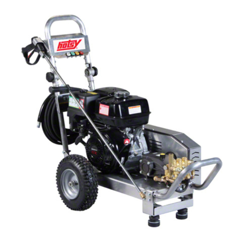
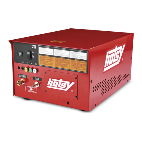
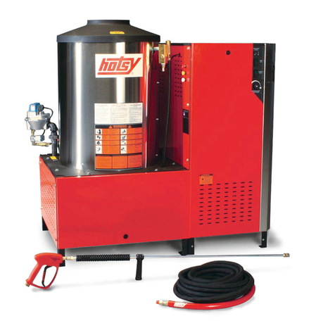
Hotsy 1.109-691.0 User manual

WARNING:
This product and accessories may contain a chemical known to the
State of California to cause cancer and birth defects or other
reproductive harm.
For more information about this regulation: www.P65Warnings.ca.gov
9.803-324.0-AW 02/20/18
900/1400 Series
Hot Water - Gas Fired
Dealer Manual Pressure Washer
GROUND
GROUND
EXPOSEDPULLEYSAND
BELTSCANCAUSEINJURY
KEEPCLEAR WHILE MACHINERY
ISOPERATING
POLEASYCORREASEXPUESTAS
PUEDENCAUSARDAÑO
NOSE ACERQUE SI MÀQUINA ESTÁFUNCIONANDO
DESCOURROIESOUPOULIESEXPOSÉES
PEUVENTCAUSERDES BLESSURES
NEPASS’APPROCHERLORSQUEL’ APPAREILESTEN OPÉRATION
WARNING
PRECAUCIÓN/ AVERTISSEMENT
8.932-965.0
EXPOSEDPULLEYSAND
BELTSCANCAUSEINJURY
KEEPCLEAR WHILE MACHINERY
ISOPERATING
POLEASYCORREASEXPUESTAS
PUEDENCAUSARDAÑO
NOSE ACERQUE SI MÀQUINA ESTÁFUNCIONANDO
DESCOURROIESOUPOULIESEXPOSÉES
PEUVENTCAUSERDESBLESSURES
NEPASS’APPROCHERLORSQUEL’APPAREILEST EN OPÉRATION
WARNING
PRECAUCIÓN/ AVERTISSEMENT
8.932-965.0
MODED’EMPLOI
LIRELE MANUEL DE L’OPERATEUR AVANT UTILISATIONUNE
MAUVAISEUTILISATIONPEUTCAUSER DESBLESSURES
OU
DOMMAGESMATÉRIELS.
INSTRUCCIONESDE OPERACION
LEAELMANUAL DE OPERACIÓN ANTES DE USARSE.LAOPERACIÓN
INADECUADAPUEDEOCASIONARLESIONESPERSONALESODAÑOS
A LASPROPIEDADES.
OPERATINGINSTRUCTIONS
READOPERATINGMANUALBEFOREOPERATING MACHINE.
IMPROPEROPERATION MAY RESULTINPERSONAL INJURYOR
PROPERTYDAMAGE.
WARNIN
PRECAUCION/ AVERTISSEMENT
RISQUEDE FEU OU D’EXPLOSION
RIESGODE INCENDIOO EXPLOSIÓN
RISKOF FIREOREXPLOSION
• Machineneedstobe installedon non-combustible
with minimum clearanceof18”.
Beforelighting, smell allaround the appliancearea for
gas.Besure tosmell next tothebecausesomegas
isheavier than air and will settle on the If yousmell
gas,immediatelycallyourgassupplierforinstructions.If
gassuppliercannotbereached,call the department.
Donot use tools to push in or turnthe gas control knob.
Ifknob will not push in or turnbyhand, calla
servicetechnician.Usingforceor attemptingrepairmay
resultin a
or explosion.
Shouldpilotoutage occur,turncontrolk
nobtoOFF
position.Wait 5minutes beforerelighting.
Donot use this equipment if any parthas been under
water.Immediatelycallaservice technician to inspect
forrepair.
Elequipo debe ser instalado sobre un piso resistente
alincendio,con unespacio libre de 18”minimo.
Antesde encender,olfatee alrededor del aparatopara
detectar gas.Esté seguro de revisar cerca del piso,
porqueciertos gases son más pesados queel aire.Si
olfateagas,aviseinmediatamenteasu proveedorde
gas.Alnolocalizar el proveedor,llame a los bomberos.
No useherramientasparamover el controldel gas.
Sila manijanose puedeoperar conlamano, llame a
untécnico capacitado. Forzar o intentar reparareste
controlpuede resultaren un incendio o explosión.
Enel caso de apagarse el piloto,apagueyespere 5
minutosantes de encender.
Noutilice este equipo en el caso que hubiera estado
sumergidoenagua parcialototalmenteun compo-
nente.Consulteconun técnico de servicio.
Nepasinstallerce machine auxendroits où il y ades
combustibles(mêmelesplancher)dedansun demi-mètre.
Avantl’allumage,
autour del’appareil pour des
senteursde gaz.
lesodeursprès du plancher car
certainsgazsont plus lourds que l’air et s’accumulent sur
leplancher.Si vous détectez une odeur degaz, appelez
immédiatementvotre fo urnisseur de gaz.Si celui-ci ne
peutêtre joint, appeler ledépartement des incendies.
Nepasutiliserd’outilspour pousseroutournerla soupape
decontrôledugaz.Silasoupapenepeutêtreenfoncéeou
tournéeàlamain,appeleruntechnicienForcerou
essayerderéparerpeut causer un feuou une explosion.
Silepilote s’éteint,tournerla soupapedecontrôleen
positionOFF
.Attendre5minutes avant deréallumer.
Nepasutilisercetéquipementsiunepartieaétéimmergée
dansl’eau. Appeler untechnicien pour inspecter celui-ci.
8.900-990.0
CHAUD!
M O D E L S :
921N
1.109-691.0
926N
1.109-692.0
943P
1.109-695.0
943N
1.109-696.0
944P
1.109-697.0
944N
1.109-698.0
942P
1.109-693.0
942N
1.109-694.0
945P
1.109-699.0
921P
1.109-948.0
945N
1.109-700.0
926P
1.109-949.0
1453P
1.109-704.0
1453N
1.109-705.0
1454P
1.109-706.0
1452P
1.109-702.0
1454N
1.109-707.0
1452N
1.109-703.0
1455P
1.109-708.0
1455N
1.109-709.0
1451N
1.109-701.0
1456N
1.109-710.0
1473N
1.109-713.0
1474N
1.109-714.0
1451P
1.109-950.0
1475P
1.109-952.0
1473P
1.109-711.0
1474P
1.109-712.0
1456P
1.109-951.0
1475N
1.109-953.0
For the Hotsy Dealer nearest you,
consult our webpage at
www.hotsy.com

2Hotsy 900/1400 Series Dealer Manual 9.803-324.0 - AW
Machine Data Label
Pump Switch
Detergent
Steam Combination
Hour Meter
Motor Overload
When the light is on, it means the overload is tripped.
Reset overload.
Pilot Light
When the light is on, it means there is power to the pilot control.
If there is no light, see troubleshooting guide.
Voltage
When the light is on, it means power supply is on
Burner Switch
Identification of Operational Label Symbols
Not all machines have all symbols

3
Table of Contents
Machine Data Label. . . . . . . . . . . . . . . . . . . . . . . . . .2
Table of Contents . . . . . . . . . . . . . . . . . . . . . . . . . . .3
How To Use This Manual . . . . . . . . . . . . . . . . . . . . .4
Safety
Introduction & Safety Information . . . . . . . . . . . . . . .5
Owner/User Responsibility . . . . . . . . . . . . . . . . . . . .5
IMPORTANT SAFETY INFORMATION . . . . . . . . . .5
Propane Tank Safety Instructions. . . . . . . . . . . . . . .8
Operations
Technical Specifications . . . . . . . . . . . . . . . . . . . . . .9
Component Identification . . . . . . . . . . . . . . . . . . . .12
Assembly Instructions . . . . . . . . . . . . . . . . . . . . . . . 13
Installation Instructions . . . . . . . . . . . . . . . . . . . . . .14
Operation Instructions. . . . . . . . . . . . . . . . . . . . . . .18
Shutdown Instructions. . . . . . . . . . . . . . . . . . . . . . .20
Storage Instructions . . . . . . . . . . . . . . . . . . . . . . . .20
Maintenance
Pump. . . . . . . . . . . . . . . . . . . . . . . . . . . . . . . . . . . .21
Gas Burner . . . . . . . . . . . . . . . . . . . . . . . . . . . . . . .21
Heating Coil . . . . . . . . . . . . . . . . . . . . . . . . . . . . . . 21
Smart Relay Instructions. . . . . . . . . . . . . . . . . . . . .22
Programming Instructions . . . . . . . . . . . . . . . . . . . . 22
Troubleshooting . . . . . . . . . . . . . . . . . . . . . . . . . . . 26
Burner Troubleshooting . . . . . . . . . . . . . . . . . . . . .28
Parts
Frame Bolt Up. . . . . . . . . . . . . . . . . . . . . . . . . . . . 32
Burner Box . . . . . . . . . . . . . . . . . . . . . . . . . . . . . . 34
Coil . . . . . . . . . . . . . . . . . . . . . . . . . . . . . . . . . . . . 36
Pump & Unloader . . . . . . . . . . . . . . . . . . . . . . . . . 38
Float Tank . . . . . . . . . . . . . . . . . . . . . . . . . . . . . . . 40
Tensioner . . . . . . . . . . . . . . . . . . . . . . . . . . . . . . . 42
Electrical Box . . . . . . . . . . . . . . . . . . . . . . . . . . . . 44
Component Cube . . . . . . . . . . . . . . . . . . . . . . . . . 46
Power Side . . . . . . . . . . . . . . . . . . . . . . . . . . . . . . 48
Panel & Doors. . . . . . . . . . . . . . . . . . . . . . . . . . . . 50
Hose, Gun, & Wand . . . . . . . . . . . . . . . . . . . . . . . 52
Specifications . . . . . . . . . . . . . . . . . . . . . . . . . . . . 54
HM.3 Series Pump . . . . . . . . . . . . . . . . . . . . . . . . 56
VB9 Unloader . . . . . . . . . . . . . . . . . . . . . . . . . . . . 58
Wiring Diagram - 900/1400 3PH W / Elec Ignition 60
Hotsy 900/1400 Series Dealer Manual 9.803-324.0 - AW

4
How To Use This Manual
This manual contains the following sections:
• How to Use This Manual
•Safety
• Operations
• Maintenance
• Parts List
The HOW TO USE THIS MANUAL section will tell you
how to find important information for ordering correct
repair parts.
Parts may be ordered from authorized dealers. When
placing an order for parts, the machine model and
machine serial number are important. Refer to the
MACHINE DATA box which is filled out during the
installation of your machine. The MACHINE DATA box
is located on the inside of the front cover of this manual.
The model and serial number of your machine is
located on the back of the machine.
The SAFETY section contains important information
regarding hazardous or unsafe practices of the
machine. Levels of hazards are identified that could
result in product damage, personal injury, or severe
injury resulting in death.
The OPERATIONS section is to familiarize the operator
with the operation and function of the machine.
The MAINTENANCE section contains preventive main-
tenance to keep the machine and its components in
good working condition. They are listed in this general
order:
•Pump
• Gas Burner
•HeatingCoil
• Smart Relay Instructions
• Troubleshooting
• Burner Troubleshooting
The PARTS LIST section contains assembled parts
illustrations and corresponding parts list. The parts lists
include a number of columns of information:
•REF – column refers to the reference number
on the parts illustration.
•PART NO. – column lists the part number for
the part.
•QTY – column lists the quantity of the part used
in that area of the machine.
•DESCRIPTION – column is a brief description
of the part.
•NOTES – column for information not noted by
the other columns.
NOTE: If a service or option kit is installed on your
machine, be sure to keep the KIT INSTRUCTIONS
which came with the kit. It contains replacement parts
numbers needed for ordering future parts.
NOTE: The manual part number is located on the
lower right corner of the front cover.
Model:
Date of Purchase:
Serial Number:
Dealer:
Address:
Phone Number:
Sales Representative:
Hotsy 900/1400 Series Dealer Manual 9.803-324.0 - AW

5
Safety
Introduction & Safety Information
Thank you for purchasing this Pressure Washer. We
reserve the right to make changes at any time
without incurring any obligation.
WARNING: If you do not follow these instructions
exactly, a fire or explosion may result causing
property damage, personal injury or death.
AVERTISSEMENT: Si ces directives ne sont pas
suivies à la lettre, un incendie ou une explosion
pourrait survenir et entraîner des dommages à la
propriété, des lésions corporelles ou la mort.
Do not store or use gasoline or other flammable vapors
and liquids in the vicinity of this or any other appliance.
WHAT TO DO IF YOU SMELL GAS
• Do not try to light any appliance.
• Do not touch any electrical switch; do not use any
phone in your building.
• Immediately call your gas supplier from a
neighbor’s phone. Follow the gas supplier’s
instructions.
• If you cannot reach your gas supplier, call the fire
department.
Installation and service must be performed by a
qualified installer, service agency or the gas supplier.
Owner/User Responsibility
The owner and/or user must have an understanding of the
manufacturer’s operating instructions and warnings before
using this pressure washer. Warning information should
be emphasized and understood. If the operator is not
fluent in English, the manufacturer’s instructions and
warnings shall be read to and discussed with the operator
in the operator’s native language by the purchaser/owner,
making sure that the operator comprehends its contents.
Owner and/or user must study and maintain for future
reference the manufacturers’ instructions.
The operator must know how to stop the machine quickly
and understand the operation of all controls.
SAVE THESE INSTRUCTIONS
This manual should be considered a permanent part
of the machine and should remain with it if machine is
resold.
When ordering parts, please specify model and
serial number. Use only identical replacement parts.
This machine is to be used only by trained operators.
IMPORTANT SAFETY INFORMATION
WARNING: If you do not follow these instructions
exactly, a fire or explosion may result, causing
property damage, personal injury or loss of life.
AVERTISSEMENT: Si ces directives ne sont pas
suivies à la lettre, un incendie ou une explosion
pourrait survenir et entraîner des dommages à la
propriété, des lésions corporelles ou la mort.
WARNING: To reduce the risk of
injury, read operating instructions
carefully before using.
AVERTISSEMENT: Pour réduire le
risque de blessures, lire attentive-
ment les instructions de fonctionne-
ment avant l'utilisation.
1. Read the owner's manual thor-
oughly. Failure to follow instruc-
tions and warnings could cause
malfunction of the machine and result in death,
serious bodily injury and/or property damage.
2. Know how to stop the machine and bleed pressure
quickly. Be thoroughly familiar with the controls.
3. Stay alert — watch what you are doing.
4. Use only your hand to push in or turn the gas control
knob. Never use a tool. If the knob will not push in or
turn by hand, don't try to repair it; call a qualified
service technician.
5. All installations must comply with local codes. Contact
your electrician, plumber, utility company or the
selling dealer for specific details.
WARNING: Use vapor fuel only.
AVERTISSEMENT: Utiliser des vapeurs de carburant
seulement
WARNING: Must be plugged into properly wired three
hole grounded outlet that accommodates plug on
power cord. Failure to comply could result in elec-
trical shock.
AVERTISSEMENT: Doit être raccordé dans une sortie
à trois trous mise à la masse et correctement câblée
qui peut accueillir une fiche sur un cordon
d'alimentation.
WARNING: To reduce the risk of electric shock,
disconnect all electrical connections and shut-off gas
valve before servicing.
AVERTISSEMENT: Pour réduire le risque de choc
électrique, débrancher toutes les connexions
électriques et la soupape de coupure des gaz avant
d'effectuer des opérations d'entretien.
Hotsy 900/1400 Series Dealer Manual 9.803-324.0 - AW
WARNING
READ OPERATOR’S
MANUAL THOROUGHLY
PRIOR TO USE.
OPERATIONS
SAFETY
MAINTENANCE

6
Safety
DANGER: Improper connection of the equipment
grounding conductor can result in a risk of electrocu-
tion. Check with a qualified electrician or service
personnel if you are in doubt as to whether the outlet
is properly grounded.
DANGER: Une mauvaise connexion du conducteur de
terre de l'équipement peut entraîner un risque
d'électrocution. Vérifier auprès d'un électricien
qualifié ou du personnel d'entretien si vous avez des
doutes quant à savoir si la sortie est correctement
mise à la masse.
DANGER: Keep wand, hose, and
water spray away from electric
wiring or fatal electric shock may
result.
DANGER: Garder la lance, le boyau
et le jet d'eau à l'écart de tout
câblage électrique ou des chocs
électriques mortels pourraient
survenir.
6. To protect the operator from electrical shock, the
machine must be electrically grounded. It is the
responsibility of the owner to connect this machine to
a grounded receptacle of proper voltage and
amperage ratings. Do not spray water on or near
electrical components. Do not touch machine with wet
hands or while standing in water. Always disconnect
power before servicing.
WARNING: Flammable liquids can create fumes which
can ignite, causing property damage or severe injury.
AVERTISSEMENT: Des liquides inflammables peuvent
produire des vapeurs qui peuvent s'enflammer,
causant ainsi des dommages à la propriété ou des
blessures graves.
WARNING: Risk of explosion —
Operate only where open flame or
torch is permitted. Do not spray
flammable liquids.
AVERTISSEMENT: Risque d'explo-
sion-Utiliser uniquement dans des
endroits où l'utilisation d'une
flamme nue ou d'une torche est
permise. Ne pas pulvériser de
liquides inflammables.
WARNING: Risk of fire — Do not
change LP tanks when the product
is operating or still hot.
AVERTISSEMENT: Risque
d'incendie-Ne pas changer les
réservoirs de pétrole liquide
pendant que le produit est en
marche ou encore chaud.
7. Gas appliances shall be installed only in locations
where combustible dusts and flammable gases or
vapors are not present. Do not store or use gasoline
near this machine.
WARNING: In the event of a pilot outage, wait at least
five minutes to clear out any gas before relighting.
AVERTISSEMENT: En cas de panne de la veilleuse,
attendre au moins cinq minutes pour permettre au
gaz de se dissiper avant de rallumer.
8. Keep operating area clear of all persons.
WARNING: High pressure spray can
cause paint chips or other particles
to become airborne and fly at high
speeds. To avoid personal injury,
eye, face, hand and foot safety
devices must be worn.
AVERTISSEMENT: Un jet haute
pression peut écailler la peinture ou
provoquer l'émission d'autres
particules dans l'air et leur
projection à hautes vitesses. Pour éviter les lésions
corporelles, une protection des yeux, du visage, des
mains et des pieds doit être portée lors de l'utilisation
de cet équipement.
9. Always wear properly rated eye protection such as
safety goggles or face shield while spraying.
(Safety glasses do not provide full protection)
WARNING: This machine exceeds 85
db appropriate ear protection must
be worn.
AVERTISSEMENT: Cette machine
excède 85 dB et une protection de
l'ouïe appropriée doit être portée.
WARNING: Risk of injury. Hot
surfaces can cause burns. Use only
designated gripping areas of spray
gun and wand. Do not place hands or
feet on non-insulated areas of the
pressure washer.
AVERTISSEMENT: Risque de
blessures. Les surfaces chaudes
peuvent causer des brûlures. Utiliser
uniquement les zones de prise
désignées du pistolet pulvérisateur et de la lance. Ne
pas placer les mains ou les pieds sur des endroits
non isolés de la laveuse à pression.
10. To reduce risk of injury, close supervision is
necessary when a machine is used near children. Do
Hotsy 900/1400 Series Dealer Manual 9.803-324.0 - AW
WARNING
RISK OF EXPLOSION:
IF GAS SMELL
PRESENT TURN OFF
SUPPLY
WARNING
RISK OF FIRE.
DO NOT ADD FUEL
WHEN OPRERATING
MACHINE.
WARNING
USE PROTECTIVE
EYE WEAR
AND CLOTHING
WHEN OPERATING
THIS EQUIPMENT.
WARNING
EAR PROTECTION
MUST BE WORN
DANGER
KEEP WATER
SPRAY AWAY FROM
ELECTRICAL WIRING.
WARNING
RISK OF INJURY.
HOT SURFACES
CAN CAUSE BURNS

7
Safety
not allow children to operate pressure washer. This
machine must be attended during operation.
WARNING: Grip cleaning wand
securely with both hands before
starting. Failure to do this could
result in injury from a whipping
wand.
AVERTISSEMENT: Agripper la lance
de nettoyage avec les deux mains
avant de commencer. Le non-
respect de cette consigne pourrait
mener à des blessures causées par
le mouvement violent de la lance.
11. Never make adjustments on machine while in opera-
tion.
12. Move spray gun trigger lever into locked position
before inserting the high pressure nozzle into the
quick coupler. Be certain all quick coupler fittings are
secured before using pressure washer.
WARNING: High pressure
developed by these machines will
cause personal injury or equipment
damage. Keep clear of nozzle. Use
caution when operating. Do not
direct discharge stream at people
or animals, or severe injury or
death will result.
AVERTISSEMENT: La haute
pression générée par ces machines
causera des lésions corporelles ou des dommages à
l'équipement. Se tenir à l'écart de la buse. Faire
preuve de prudence lors de l'utilisation. Ne pas
décharger directement le jet vers des personnes ou
des animaux, car cela risquerait de causer des
blessures graves ou même la mort.
WARNING: Protect machine from
freezing.
AVERTISSEMENT: Protéger la
machine contre le gel.
13. To keep machine in best operating
conditions, it is important you
protect machine from freezing.
Failure to protect machine from
freezing could cause malfunction
of the machine and result in death,
serious bodily injury, and/or property damage. Follow
storage instructions specified in this manual.
WARNING: Risk of asphyxiation.
Use this product only in a well
ventilated area.
AVERTISSEMENT: Risque
d'asphyxie: Utiliser ce produit
uniquement dans un endroit bien
ventilé.
14. Avoid installing machines in small
areas or near exhaust fans.
Adequate oxygen is needed for
combustion or dangerous carbon monoxide will
result.
15. Manufacturer will not be liable for any changes made
to our standard machines or any components not
purchased from us.
16. The best insurance against an accident is precaution
and knowledge of the machine.
WARNING: Be extremely careful
when using a ladder, scaffolding or
any other relatively unstable
location. The cleaning area should
have adequate slopes and drainage
to reduce the possibility of a fall due
to slippery surfaces.
AVERTISSEMENT: Faire preuve
d'une extrême prudence au moment
d'utiliser une échelle, des
échafaudages ou toute autre surface relativement
instable. La zone de nettoyage doit avoir une pente et
un drainage adéquats pour réduire la possibilité d'une
chute due à une surface glissante.
17. Do not overreach or stand on unstable support. Keep
good footing and balance at all times.
18. Do not operate this machine when fatigued or under
the influence of alcohol, prescription medications, or
drugs.
WARNING: Use vapor fuel only.
AVERTISSEMENT: Utiliser des vapeurs de carburant
seulement.
19. The LP models are designed to run on vapor propane
fuel. Do not use liquid fuel. Have a qualified
serviceman install and service your equipment.
20. Never expose a spark or flame where there may be
unburned gas present.
21. Install this machine about 2 feet from wall to provide
adequate ventilation and servicing space. This
equipment incorporates parts such as snap switches
or similar parts that tend to produce arcs or sparks.
Therefore, when located in a garage, it should be in a
room or enclosure provided for the purpose or should
be installed 18" (457mm) or more above the floor.
Hotsy 900/1400 Series Dealer Manual 9.803-324.0 - AW
WARNING
TRIGGER GUN KICKS
BACK — HOLD WITH
BOTH HANDS
WARNING
RISK OF INJECTION
OR SEVERE INJURY
TO PERSONS. KEEP
CLEAR OF NOZZLE.
WARNING
PROCTECT FROM
FREEZING
WARNING
RISK OF
ASPHYXIATION.
USE THIS PRODUCT
ONLY IN A WELL
VENTILATED AREA.
WARNING
RISK OF INJURY
FROM FALLS WHEN
USING LADDER.

8
Safety
22. This equipment must be installed on noncombustible
flooring and have a 36” (90cm) minimum working
clearance.
23. Do not allow acids, caustic or abrasive fluids to pass
through the pump.
24. Never run pump dry or leave spray gun closed longer
than 3 minutes.
25. Exhaust gases should not be vented into a wall, a
ceiling or a concealed space of a building. A draft
diverter must be installed to prevent down draft and to
allow cooling of exhaust temperatures. Down draft
diverters shall be installed in the vents and located at
a distance from the pressure washer stack to achieve
maximum draft of 36" minimum. Exhaust gases that
exceed 470°F (243°C) are not suitable for connection
to Type B gas vents.
Example of Down Draft Diverter
for Gas Fired Machines
WARNING: If connection is made to
potable water supply, a back flow
device must be provided.
AVERTISSEMENT: Si une
connexion est établie avec un
réseau d'eau potable, le réseau doit
être protégé contre le retour d'eau.
WARNING: Do not spray machine
or any people, animals or electrical
parts.
AVERTISSEMENT: Ne pas
vaporiser sur la machine ou les
gens, les animaux ou les pièces
électriques.
Follow the maintenance instructions
specified in the manual.
Propane Tank Safety Instructions
CAUTION: Only qualified persons should fill your LP-
gas containers.
ATTENTION: Les contenants de gaz de pétrole
liquéfié doivent être remplis uniquement par des
personnes qualifiées.
1. Never allow your LP-gas container to be filled above
the maximum safe level as indicated by a scale or the
fixed liquid level gauge (outage). Do not use the
visible gauge for filling.
2. Do not use a wrench or pliers to close the service
valve or fixed liquid level gauge. These valves are
designed to be closed leak-tight by hand or screw-
driver as appropriate. If wrenches are necessary to
stop a leak, the valve needs repair or replacement.
3. When tightening the POL Nut (left hand thread) on the
service valve, draw it up snug with a proper wrench.
This is a machined male brass fitting which seats
securely against a female seat in the POL valve – no
pipe dope is necessary. Acme/Type 1 valves have
right handed threads which are secure when hand
tight, and on the Quick Disconnect/Type 2 Valves, the
male connection is inserted into the female connec-
tion on the cylinder valve. (No wrenches required for
both the Acme and the Quick Disconnect.)
4. When using container, slowly open service valve all
the way. Listen to the regulator. A continuous hiss
may indicate a leak or an open valve on an appliance.
5. Check all tank and the line connections periodically to
be sure they are tight. When testing for leaks, use
approved leak detector solution – not matches.
6. Make certain your container is properly fastened in
place.
7. Turn container with open part of container guard
towards frame. This protects valves and regulator
against flying rocks and mud. Transport container in
the proper position in which it is used, with the valves
closed and POL Plugs inserted for POL Valves or
Dust Caps for Acme Valves. Secure the tank against
falling or rolling.
8. Check for leaks after connecting. Apply approved leak
detector solution to connection, turn off all burners
and pilots, and open service valve. Leaks will be
detected by the growth of the bubbles. If bubbles
grow, tighten or repair the connection as needed.
Repeat leak test until problem is corrected.
9. LP-gas is normally non-corrosive – you need not
worry about the inside of your container. However, the
outside should be kept free from rust by a periodic
coat of paint in a light reflective color. It is very
important to inspect and maintain the bottom and foot
ring on the container.
10. Do not store LP-gas containers indoors or in enclosed
areas. Do not expose LP-gas container to heat.
Always store with service valve closed and plugged
as required.
11. Do not attempt to repair any containers, container
valves, regulator or appliances by yourself. Use only
trained certified LP-gas service personnel to perform
repairs.
WARNING
IF CONNECTED
TO A POTABLE
WATER SUPPLY,
PROTECT AGAINST
BACKFLOW.
WARNING
DO NOT SPRAY
MACHINE OR ANY
PEOPLE, ANIMALS OR
ELECTRICAL PARTS.
Hotsy 900/1400 Series Dealer Manual 9.803-324.0 - AW

9
Operations
Technical Specifications
Model #
Pump
Volume @
Pump
Head
Pump
Pressure
at Pump
Head
Burner Type Motor HP Machine
Voltage
Total
Machine
Amperage
Machine
Weight
921N 4.0 GPM /
228 GPH 2300 PSI Natural Gas Fired,
364,835 BTU/Hr. 6.2 HP 208VAC/
60Hz/1Ph 28 Amps 560 Lbs
926N 4.0 GPM /
228 GPH 2000 PSI Natural Gas Fired,
364,835 BTU/Hr. 5 HP 575VAC/
60Hz/3Ph 7 Amps 555 Lbs
943P 4.0 GPM /
234 GPH 2000 PSI LP Gas Fired,
360,997 BTU/Hr. 5.0 HP 230VAC/
60Hz/1Ph 25 Amps 550 Lbs
943N 4.0 GPM /
234 GPH 2000 PSI Natural Gas Fired,
364,835 BTU/Hr. 5.0 HP 230VAC/
60Hz/1Ph 25 Amps 550 Lbs
944P 4.0 GPM /
234 GPH 2000 PSI LP Gas Fired,
360,997 BTU/Hr. 5.0 HP 230VAC/
60Hz/3Ph 25 Amps 545 Lbs
944N 4.0 GPM /
234 GPH 2000 PSI Natural Gas Fired,
364,835 BTU/Hr. 5.0 HP 230VAC/
60Hz/3Ph 16 Amps 545 Lbs
942P 4.0 GPM /
234 GPH 2000 PSI LP Gas Fired,
360,997 BTU/Hr. 5.0 HP 200VAC/
60Hz/3Ph 18 Amps 545 Lbs
942N 4.0 GPM /
234 GPH 2000 PSI Natural Gas Fired,
364,835 BTU/Hr. 5.0 HP 200VAC/
60Hz/3Ph 18 Amps 545 Lbs
945P 4.0 GPM /
234 GPH 2000 PSI LP Gas Fired,
360,997 BTU/Hr. 5.0 HP 460VAC/
60Hz/3Ph 8 Amps 545 Lbs
945N 4.0 GPM /
234 GPH 2000 PSI Natural Gas Fired,
364,835 BTU/Hr. 5.0 HP 460VAC/
60Hz/3Ph 8 Amps 545 Lbs
1453P 4.0 GPM /
234 GPH 3000 PSI LP Gas Fired,
360,997 BTU/Hr. 7.5 HP 230VAC/
60Hz/1Ph 34 Amps 610 Lbs
1453N 4.0 GPM /
234 GPH 3000 PSI Natural Gas Fired,
364,835 BTU/Hr. 7.5 HP 230VAC/
60Hz/1Ph 34 Amps 610 Lbs
1454P 4.0 GPM /
234 GPH 3000 PSI LP Gas Fired,
360,997 BTU/Hr. 7.5 HP 230VAC/
60Hz/3Ph 25 Amps 605 Lbs
1452P 4.0 GPM /
234 GPH 3000 PSI LP Gas Fired,
360,997 BTU/Hr. 7.5 HP 208VAC/
60Hz/3Ph 24 Amps 605 Lbs
1454N 4.0 GPM /
234 GPH 3000 PSI Natural Gas Fired,
364,835 BTU/Hr. 7.5 HP 230VAC/
60Hz/3Ph 24 Amps 605 Lbs
1452N 4.0 GPM /
234 GPH 3000 PSI Natural Gas Fired,
364,835 BTU/Hr. 7.5 HP 208VAC/
60Hz/3Ph 24 Amps 605 Lbs
1455P 4.0 GPM /
234 GPH 3000 PSI LP Gas Fired,
360,997 BTU/Hr. 7.5 HP 460VAC/
60Hz/3Ph 12 Amps 605 Lbs
1455N 4.0 GPM /
234 GPH 3000 PSI Natural Gas Fired,
364,835 BTU/Hr. 7.5 HP 460VAC/
60Hz/3Ph 12 Amps 605 Lbs
1451N 4.0 GPM /
234 GPH 3000 PSI Natural Gas Fired,
364,835 BTU/Hr. 8.2 HP 208VAC/
60Hz/1Ph 36.5 Amps 615 Lbs
1456N 4.0 GPM /
234 GPH 3000 PSI Natural Gas Fired,
364,835 BTU/Hr. 8.2 HP 575VAC/
60Hz/3Ph 10 Amps 615 Lbs
Hotsy 900/1400 Series Dealer Manual 9.803-324.0 - AW

10
Operations
Technical Specifications
Model # Shipping Weight Exhaust Stack Size Machine Dimensions
921N 620 Lbs 8” L 47.5” X W 21” X H 51”
926N 610 Lbs 8” L 47.5” X W 21” X H 51”
943P 610 Lbs 8” L 47.5” X W 21” X H 51”
943N 610 Lbs 8” L 47.5” X W 21” X H 51”
944P 605 Lbs 8” L 47.5” X W 21” X H 51”
944N 605 Lbs 8” L 47.5” X W 21” X H 51”
942P 605 Lbs 8” L 47.5” X W 21” X H 51”
942N 605 Lbs 8” L 47.5” X W 21” X H 51”
945P 605 Lbs 8” L 47.5” X W 21” X H 51”
945N 605 Lbs 8” L 47.5” X W 21” X H 51”
1453P 670 Lbs 8” L 47.5” X W 21” X H 51”
1453N 670 Lbs 8” L 47.5” X W 21” X H 51”
1454P 665 Lbs 8” L 47.5” X W 21” X H 51”
1452P 665 Lbs 8” L 47.5” X W 21” X H 51”
1454N 665 Lbs 8” L 47.5” X W 21” X H 51”
1452N 665 Lbs 8” L 47.5” X W 21” X H 51”
1455P 665 Lbs 8” L 47.5” X W 21” X H 51”
1455N 665 Lbs 8” L 47.5” X W 21” X H 51”
1451N 675 Lbs 8” L 47.5” X W 21” X H 51”
1456N 675 Lbs 8” L 47.5” X W 21” X H 51”
Hotsy 900/1400 Series Dealer Manual 9.803-324.0 - AW

11
Operations
Model #
Pump
Volume @
Pump
Head
Pump
Pressure
at Pump
Head
Burner Type Motor HP Machine
Voltage
Total
Machine
Amperage
Machine
Weight
1473N 5 GP /
300 GPH 3000 PSI Natural Gas Fired,
390,025 BTU/Hr. 10 HP 230VAC/
60Hz/1Ph 42 Amps 617 Lbs
1474N 5 GPM/
300 GPH 3000 PSI LP Gas Fired,
390,025 BTU/Hr. 10 HP 230VAC/
60Hz/3Ph 29 Amps 620 Lbs
921P 4.0 GPM /
234 GPH 2300 PSI LP Gas Fired,
360,997 BTU/Hr. 6.2 HP 208VAC/
60Hz/1Ph 28 Amps 560 Lbs
926P 4.0 GPM /
234 GPH 2000 PSI Natural Gas Fired,
360,997 BTU/Hr. 5.0 HP 575VAC/
60Hz/3Ph 7 Amps 555 Lbs
1473P 5 GPM /
300 GPH 3000 PSI LP Gas Fired,
378,617 BTU/Hr. 10 HP 230VAC/
60Hz/1Ph 42 Amps 617 Lbs
1474P 5 GPM /
300 GPH 3000 PSI LP Gas Fired,
378,617 BTU/Hr. 10 HP 230VAC/
60Hz/3Ph 29 Amps 620 Lbs
1451P 4.0 GPM /
234 GPH 3000 PSI LP Gas Fired,
360,997 BTU/Hr. 8.2 HP 208VAC/
60Hz/1Ph 36.5 Amps 615 Lbs
1456P 4.0 GPM
234 GPH 3000 PSI LP Gas Fired,
360,997 BTU/Hr 8.2 HP 575VAC/
60Hz/1Ph 10 Amps 615 Lbs
1475P 5.0 GPM /
300 GPH 3000 PSI LP Gas Fired,
360,997 BTU/Hr 10 HP 200VAC/
60Hz/3Ph 34 Amps 620 Lbs
1475N 5.0 GPM/
300 GPH 3000 PSI LP Gas Fired,
378,617 BTU/Hr. 10 HP 200VAC/
60Hz/3Ph 34 Amps 620 Lbs
Model # Shipping Weight Exhaust Stack Size Machine Dimensions
1473N 677 Lbs 8” L 47.5” X W 21” X H 51”
1474N 680 Lbs 8” L 47.5” X W 21” X H 51”
921P 620 Lbs 8” L 47.5” X W 21” X H 51”
926P 610 Lbs 8” L 47.5” X W 21” X H 51”
1473P 677 Lbs 8” L 47.5” X W 21” X H 51”
1474P 680 Lbs 8” L 47.5” X W 21” X H 51”
1451P 675 Lbs 8” L 47.5” X W 21” X H 51”
1456P 675 Lbs 8” L 47.5” X W 21” X H 51”
1475P 680 Lbs 8” L 47.5” X W 21” X H 51”
1475N 680 Lbs 8” L 47.5” X W 21” X H 51”
Hotsy 900/1400 Series Dealer Manual 9.803-324.0 - AW

12
Operations
Component Identification
Pump — Develops high pressure by pumping water
volume through nozzle.
Spray Gun — Controls the application of water and
detergent onto cleaning surface with trigger device.
Includes safety latch.
Detergent Metering Valve — Controls detergent
mixture.
Wand — Must be connected to the spray gun.
Relief Valve — Safety device preventing over-pressur-
ization.
High Pressure Hose — Connect one end to water
pump discharge nipple and the other end to spray gun.
Pressure Nozzle — Inserted into wand quick coupler
to develop pressure
Adjustable Thermostat — Prevents water tempera-
ture from exceeding high temperatures. Is not used to
maintain constant temperature setting.
Safety Trigger Lever — Prevents accidental triggering
of spray gun while inserting a high pressure nozzle.
Bend Restrictor (Shroud) — This shroud has different
lengths depending on pressure. The largest shroud
must be connected to the spray gun to protect operator
if hose becomes separated.
Hotsy 900/1400 Series Dealer Manual 9.803-324.0 - AW
GROUND
GROUND
EXPOSEDPULLEYSAND
BELTSCANCAUSEINJURY
KEEPCLEARWHILE MACHINERY
ISOPERATING
POLEASYCORREASEXPUESTAS
PUEDENCAUSARDAÑO
NOSEACERQUE SI MÀQUINA ESTÁFUNCIONANDO
DESCOURROIESOUPOULIESEXPOSÉES
PEUVENTCAUSERDESBLESSURES
NEPASS’APPROCHER LORSQUE L’APPAREILEST EN OPÉRATION
WARNING
PRECAUCIÓN/ AVERTISSEMENT
8.932-965.0
EXPOSEDPULLEYS AND
BELTS CANCAUSEINJURY
KEEPCLEARWHILE MACHINERY
ISOPERATING
POLEASYCORREASEXPUESTAS
PUEDENCAUSARDAÑO
NOSEACERQUE SIMÀQUINA ESTÁFUNCIONANDO
DESCOURROIESOUPOULIESEXPOSÉES
PEUVENTCAUSERDESBLESSURES
NEPASS’APPROCHERLORSQUE L’APPAREIL EST EN OPÉRATION
WARNING
PRECAUCIÓN/ AVERTISSEMENT
8.932-965.0
MODED’EMPLOI
LIRELEMANUEL DEL’OPERATEUR AVANT UTILISATION UNE
MAUVAISEUTILISATION PEUT CAUSERDES BLESSURESOU
DOMMAGESMATÉRIELS.
INSTRUCCIONESDE OPERACION
LEAELMANUAL DEOPERACIÓN ANTES DE USARSE.LAOPERACIÓN
INADECUADAPUEDEOCASIONARLESIONESPERSONALESO DAÑOS
ALASPROPIEDADES.
OPERATINGINSTRUCTIONS
READOPERATINGMANUALBEFOREOPERATINGMACHINE.
IMPROPEROPERATIONMAYRESULTINPERSONALINJURYOR
PROPERTYDAMAGE.
WARNIN
PRECAUCION/ AVERTISSEMENT
RISQUEDE FEUOU D’EXPLOSION
RIESGODE INCENDIOO EXPLOSIÓN
RISKOF FIREOR EXPLOSION
• Machineneedstobeinstalledonnon-combustible
with minimum clearance of 18”.
Beforelighting, smell all around theappliance area for
gas.Besureto smellnextto thebecausesome gas
isheavierthan air andwill settle on the If you smell
gas,immediatelycallyourgassupplierforinstructions.If
gassuppliercannotbereached,callthe department.
Do notusetools to push in orturnthe gas control knob.
Ifknobwillnotpushin or turnby hand,call a
servicetechnician.Usingforceorattemptingrepairmay
resultina
or explosion.
Shouldpilotoutage occur,turncontrolknobt
oOFF
position.Wait5 minutes beforerelighting.
Donot usethis equipment if anyparthasbeenunder
water.Immediatelycallaservice technician toinspect
forrepair.
El equipo debe ser instalado sobre unpisoresistente
alincendio,conun espacio libre de 18” minimo.
Antes deencender,olfateealrededordel aparatopara
detectargas.Esté seguro de revisar cercadel piso,
porqueciertos gases sonmáspesadosque el aire.Si
olfateagas,aviseinmediatamentea suproveedor de
gas.Alnolocalizarelproveedor,llame alos bomberos.
Nouseherramientasparamover el controldel gas.
Sila manijano sepuedeoperarconlamano, llame a
untécnico capacitado.Forzar o intentarreparar este
controlpuede resultaren un incendio oexplosión.
En el caso de apagarse el piloto,apagueyespere5
minutosantesdeencender.
Noutilice este equipo enel caso que hubiera estado
sumergidoenaguaparcial ototalmenteun compo-
nente.Consulteconuntécnico deservicio.
Nepasinstallerce machineaux endroits où ily a des
combustibles(mêmelesplancher)dedans un demi-mètre.
Avantl’allumage,
autourdel’appareilpour des
senteursdegaz.
lesodeursprèsduplancher car
certainsgazsontpluslourdsque l’air et s’accumulentsur
leplancher.Si vous détectez une odeurde gaz, appelez
immédiatementvotrefournisseur degaz.Si celui-cine
peutêtrejoint, appeler ledépartementdesincendies.
Nep asutiliserd’outilspourpousseroutourner las oupape
decontrôledugaz.Silasoupapene peut être enfoncéeou
tournéeàlamain,appelerun t echnicienForcerou
essayerderéparerpeut causer un feu ou une explosion.
Silep
ilotes’éteint,tournerlasoupape de contrôleen
positionOFF
.Attendre5minutesavantde réallumer.
Nepasutilisercetéquipementsiunepartieaétéimmergée
dansl’eau.Appelerun technicien pour inspectercelui-ci.
8.900-990.0
CHAUD!
High Pressure
Hose
Inlet Power
Junction Box
Burner
Exhaust Vent
Thermostat
Pump Switch
Wand Burner
Switch
Garden Hose
(not included)
Detergent
Metering
Valve
Nozzles
Detergent Bucket
(not included)
Spray Gun
High Pressure
Nozzle
Safety Trigger
Lever
Relief
Valve
Shroud

13
Operations
Assembly Instructions
Unpacking
Unpack carefully. Wear safety glasses or goggles while
unpacking, assembling or operating pressure washer. If
there are missing components or hidden damage
immediately contact dealer or carrier concerning
discrepancies.
1. Cut strapping band from pressure washer and
pallet.
2. Remove pressure washer from pallet.
Parts Included
• Pressure Washer
• Pressure Hose
•Wand
• Parts Box Containing:
- Pressure Nozzles (3 ea.)
- Trigger Gun
• Operating Instructions and Parts Manual
Tools Required
• 10" Adjustable Crescent Wrenches (2 ea.)
• Blade Screwdriver
Pressure Hose, Wand and Wand Holder
1. Use teflon tape on plumbing connections to
prevent leakage.
2. Install pressure hose on machine as shown.
3. Assemble wand components as shown.Connect
pressure hose to trigger gun.
NOTE: The nozzle is not to be installed at this time.
Note: Pressure relief valve should be inspected and
tested annually.
4. Make sure that all plumbing connections are tight.
Note: Longer shroud at end of hose should be
connected to spray gun.
Wand
Pressure Hose
Trigger Gun
Quick Disconnect Plug
Quick
Disconnect
Shroud
Hotsy 900/1400 Series Dealer Manual 9.803-324.0 - AW
Pressure Hose
Relief Valve

14
Operations
Installation Instructions
Getting Started
IMPORTANT: Proper installation will assure satisfac-
tory performance, longer service life and lower mainte-
nance costs.
Location
The location should protect machine from damaging
environmental conditions, such as wind, rain and
freezing.
1. The machine should be run on a level surface
where it is not readily influenced by outside
sources such as strong winds, freezing tempera-
tures, rain, etc. The machine should be located
considering accessibility for the replacing of
components and the refilling of detergents, adjust-
ments and maintenance. Normal precautions
should be taken by the operator of the machine to
prevent excess moisture from reaching the
machine.
2. It is recommended that a partition be made
between the wash area and machine to prevent
direct spray from the spray gun from coming in
contact with the machine. Excess moisture
reaching the power unit or electrical controls will
reduce the machine’s life and may cause electrical
shorts.
3. During installation of the machine, beware of
poorly ventilated locations or areas where exhaust
fans may cause an insufficient supply of oxygen.
Sufficient combustion can only be obtained when
there is a sufficient supply of oxygen available for
the amount of fuel being burned. If it is necessary
to install a machine in a poorly ventilated area,
outside fresh air may have to be piped to the
burner and a fan installed to bring the air into the
area.
4. Do not locate near any combustible material. Keep
all flammable material at least 20 feet away. Allow
enough space for servicing the machine. Local
code will require certain distances from floor and
walls. (Two feet away should be adequate).
WARNING: Avoid small areas or near exhaust fans.
AVERTISSEMENT: Éviter les petites superficies ou
les surfaces à proximité des ventilateurs
d'extraction.
Gas Codes
Confer with local gas company and with proper
municipal officials regarding any specific code or regu-
lations governing the installation. The installation must
conform to local codes (U.S., ANSI Z223.1/NFPA54
National Fuel Gas Code; Canada, CAN 1-B149 Instal-
lation Code).
Electrical
The machine, when installed, must be electrically
grounded in accordance to local codes. Check for
proper power supply using a volt meter; check the
serial plate for the correct requirements.
Gas Piping
This machine shall be rigidly connected to the gas
piping outlet and equipped with external manual shut-
off valves adjacent to such machine. All gas piping shall
be approved and installed in accordance with the
Uniform Mechanical Code.
Install a gas union in the gas line adjacent to and
upstream from the control manifold and downstream
from the manual main shut-off valve. A 1/8” NPT
plugged tapping accessible for test gauge connection
shall be installed immediately upstream of the gas
supply connection for the purpose of determining the
gas supply pressure to the burner, and to prevent
damage to gas valve.
If a manual gas shut off valve is not in the gas supply
line within six feet of the machine and in an accessible
location, one shall be installed.
Union Connection
The following pipe sizes are just recommendations.
Always consult a local plumber and venting contractor
for local codes and regulations during installation.
Pipe Sizing Chart for Natural Gas
The following chart is based on gas pressure in the
range 0-0.5 psi, specific gravity of 0.6 and pressure
loss of 0.5" W.C. Numbers are for straight schedule 40
pipe; fittings further reduce capacity. For example, in 1"
size, an elbow is equivalent to about 2.6 feet of pipe
and a tee is equivalent to about 5.2 feet of pipe.
Hotsy 900/1400 Series Dealer Manual 9.803-324.0 - AW
Manual Shut-Off Valve
(Dealer Supplied)
GasValve
Union
Burner

15
Operations
Maximum capacity of pipe in cubic feet/hr of
natural gas (Multiply values by 1000 to get nominal
BTU/hr capacity.
LP-Gas (Liquid petroleum gas or propane)
LP-gas is gas compressed into liquid form for easy
transportation and storage. It is also known as propane
or bottle gas. (Propane tanks are not supplied with this
equipment.)
LP-gas is flammable, is always contained under
pressure and the liquid can freeze skin. Therefore, in
the interest of safety, it is important to understand the
basic facts about LP-gas and LP-gas containers.
Federal DOT (Department of Transportation) regula-
tions require periodic inspections and re-qualifications
of cylinders. DO NOT USE damaged or rusted
containers.
DO NOT store LP-gas containers indoors or in
enclosed areas. Do not expose LP-gas container to
heat. Always store with service valve closed and
plugged as required.
CAUTION: Use LP-gas containers in proper
position.
ATTENTION: Utiliser des contenants de gaz de
pétrole liquéfié en position appropriée.
Most LP-gas pressure washer heaters are designed to
operate on LP-gas vapor only. Therefore, all LP-gas
containers designed for vapor service must be trans-
ported, installed and used in the proper position. Do not
transport, install or use a vertical cylinder in a horizontal
or upside down position. Proper care must be taken to
position a horizontal container in the correct position for
vapor withdrawal. Liquid LP-gas could enter the system
designed for vapor only, possibly creating a hazardous
condition.
Always use a POL plug installed on a POL valve or a
dust cap on an ACME/Type 1 valve when transporting
or storing disconnected containers (full or empty).
Check for leaks after connecting. Apply approved leak
detector solution to connection, turn off all burners and
pilots and open service valve. Leaks will be detected by
the growth of bubbles. If bubbles grow, tighten or repair
the connection as needed. Repeat leak test until
problem is corrected.
Check all tank and the line connections periodically to
be sure they are tight. When testing for leaks, use
approved leak detector solution — not matches.
Improved Regulation: The second stage regulator
receives a relatively uniform pressure from the first
stage regulator. This helps the second stage regulator
to maintain appliance pressure at a nearly constant 11"
W.C.
Filling the LP-Gas Container
Only qualified persons should fill your LP-gas
containers.
Les contenants de gaz de pétrole liquéfié doivent
être remplis uniquement par des personnes
qualifiées.
CAUTION: Overfilling is hazardous!
ATTENTION: Le remplissage excessif est
dangereux!
DO NOT allow your LP-gas container to be overfilled.
Stop filling when liquid appears at the fixed level gauge.
Bleed off excess propane in a safe area. Most LP-gas
containers are equipped with a fixed liquid level gauge
which contacts the liquid level at 80% of container
capacity, allowing 20% for expansion. LP-gas
containers not equipped with a fixed liquid level gauge
can only be filled by weight.
In cold climates, in order to keep vaporization of LP-gas
at the highest level, keep the fuel levels above 50%.
Combustion and Ventilation Air
Properly sized vents are vital for the safe and efficient
operation of a pressure washer installed in a confined
space. When combustion and ventilation air are
supplied from inside the building, each opening must
have an area of one square inch for every 1,000 BTUH
input. When combustion air is supplied from the
outside, each opening must have an area of one
square inch for every 2,000 BTUH for horizontal ducts
and one square inch for every 4,000 BTUH for vertical
ducts (refer to NFPA 54).
Hotsy 900/1400 Series Dealer Manual 9.803-324.0 - AW
Length of
Pipe (ft.)
Iron Pipe Size
3/4" 1" 1 -1/4" 1- 1/2" 2"
10 360 680 1400 2100 3950
20 250 465 950 1460 2750
30 200 375 770 1180 2200
40 170 320 660 990 1900
50 151 285 580 900 1680
60 138 260 530 810 1520
70 125 240 490 750 1400
80 118 220 460 690 1300
90 110 205 430 650 1220
100 103 195 400 620 1150
150 84 160 325 500 950
200 72 135 280 430 800

16
Operations
The purpose of venting a gas pressure washer is to
completely remove all products of combustion and to
vent gasses to the outside air without condensation in
the vent or spillage at the draft hood (except in cases of
downdraft or poor stack conditions). To assure correct
venting, use a strong, gas-tight insulated pipe with a
cross section equal to that of the flue collar or draft
hood outlet and of sufficient vertical height.
During vent installation, avoid sharp turns, long hori-
zontal runs and improper pitches. Maintain proper
support of vent connectors and joints, observe clear-
ances from all combustibles and top the vent outlet with
an approved cap.
Type "B", due to its temperature rating, can only be
used with natural draft pressure washers. A "B" vent is
designed for exhaust temperatures not to exceed
470°F (245°C).
All venting installations must conform to local codes. In
the absence of local codes, refer to "National Fuel Gas
Code" NFPA 54 and be constructed of materials
approved by the Uniform Building Code.
Vents penetrating ceilings or walls should be double-
wall approved appliance vents and should be one to
two inches from combustibles. Vents passing through
enclosed spaces and vents exposed to the weather
should also be the double-wall type. Sometimes vents
have to be built of such great length that they come
apart at their joints under their own weight. These
should be screwed together at the joints with sheet
metal screws, usually three per joint. If the inspector
indicates that the vent is too close to combustibles, it
may be necessary to chisel away some of the combus-
tible or route the vent pipe around the combustible. The
cross-sectional area of any flue shall not be less that
the cross-sectional area of the flue vent connection
outlet of machine.
Ventilation
Water Source
The water source for the machine should be supplied
by a 5/8" I.D. garden hose with a city water pressure of
not less than 30 PSI. If the water supply is inadequate,
or if the garden hose is kinked, the machine will run
very rough and the burner will not fire.
Water Connection
Connect the high pressure hose by pulling the coupler
collar back and then inserting it onto the discharge
nipple. Secure it by pushing the collar forward.
Attach the wand into the spray gun using teflon tape on
the pipe threads to avoid leaks.
Hotsy 900/1400 Series Dealer Manual 9.803-324.0 - AW
Illustration showing air openings necessary
to supply air for combustion when installed
in an enclosed room.

17
Operations
Inspection and Testing Gas Piping
The building structure should not be weakened by
installing the gas piping. The piping should not be
supported by other piping, but should be firmly
supported with gas hooks, straps, bands or hangers.
Butt or lap welded pipe should not be run through or in
an air duct or clothes chute.
Before turning gas under pressure into piping, all
openings from which gas can escape should be closed.
Immediately after turning on gas, the system should be
checked for leaks. This can be done by watching the
1/2 cubic foot test dial for 5 minutes for any movement
or by soaping each pipe connection and watching for
bubbles. If a leak is found, make the necessary repairs
and repeat the above test.
Defective pipes or fittings should be replaced and not
repaired. Never use a flame or fire in any form to locate
gas leaks — use a soap solution.
After the piping and meter have been checked
completely, purge the system of air. DO NOT bleed the
air inside an enclosed room.
During pressure testing of the system at test pressures
in excess of 1/2 PSIG, the pressure washer and its indi-
vidual shut-off valve must be disconnected from gas
supply piping system or damage to the gas valve will
occur.
Gas Pressure
The ideal incoming gas pressure is 11 w.c.i (water
column inches). Minimum is 9 w.c.i., maximum is 14
w.c.i. or 1/2 PSIG. The correct operating manifold
pressure for natural gas is 2.8 w.c.i. The operating
manifold pressure for propane gas is 7.5 w.c.i. By
adjusting the gas valve pressure regulator between 3
and 4 w.c.i. a side range can be achieved for natural
gas.
If the desired input rating cannot be obtained within the
above manifold pressure adjusting range, then the next
size larger or smaller burner orifice should be used.
The gas pressure coming out of the regulator and going
to the burner ring has been factory set for elevations of
0 to 2000 ft. Altitudes greater than 2000 ft will require
adjustments to the gas manifold pressures. Consult
your local service dealer for high altitude adjustments.
In Canada, certification for installation at altitudes over
4500 feet above sea level is the jurisdiction of local
authorities. You should not readjust the burner ring gas
pressure. If you replace your gas valve, you will need to
adjust the new valve. Refer to your machine’s specifi-
cation plate for the correct pressure setting. Follow the
installation and adjustment instructions provided with
your replacement valve.
NOTE: Air for combustion and ventilation along with
exhaust flue sizing must conform to methods outlined in
current American Standard (ANSI-Z223.1) National
Fuel Gas Code or National Standard of Canada CSA-
149.1 and CSA-149.2 “Installation Code for Gas
Burning Appliances”.
Hotsy 900/1400 Series Dealer Manual 9.803-324.0 - AW
OFF
ON
Outlet View
On/Off
Switch
Manifold
Pressure Adjustment
Screw Under Cap

18
Operations
Operation Instructions
Before Starting
1. Read all manuals provided with this pressure
washer. Become familiar with location and function
of all operating and safety controls.
WARNING: Check hoses, fittings, wand, trigger gun
and fuel connections daily for signs of wear, cracks
and looseness, and replace as needed.
AVERTISSEMENT: Vérifier les boyaux, les
raccords, le pistolet à gâchette et les connexions
de carburant pour la présence de traces d'usure,
de fissures et de desserrement; remplacer au
besoin.
2. Connect water supply hose to the standard garden
hose connector. The water faucet and supply hose
must be capable of providing 6.0 GPM.
3. This machine was factory built for natural gas/
propane. See instructions under Fuel Supply.
4. Check pump oil level.
5. If detergents are to be used, only use detergents
intended for pressure washers. Follow instructions
on the detergent container.
IMPORTANT: Before installing pressure nozzle on
initial start-up, turn on the water supply, start the
pump by pressing the pump ON switch, and hold
the wand trigger open until water appears at the
end of the wand. Allow water to run from the end of
the wand until clear to prevent the nozzle from
clogging.
6. Install the pressure nozzle on end of wand, refer to
illustration below.
IMPORTANT: The trigger gun provided with this
pressure washer is equipped with a manual trigger
lock to prevent accidental operation of the trigger
gun, refer to figure above. The safety trigger lock
should be used whenever the trigger gun is not in
use.
IMPORTANT: On initial start-up or if maintenance
has been performed on the burner assembly, it will
be necessary to bleed the air from the gas line
before the pilot will light.
7. If you are running the machine for the first time, or
have performed maintenance on the burner
assembly, there will be air in the gas line. To bleed
the air from the gas line run the pressure washer
with pump and burner switches on and thermostat
on highest setting. Squeeze the trigger of the
trigger gun for 15 seconds. If the burner has not
ignited, release the trigger for 5 seconds, then
squeeze for 15 seconds. If the burner has not
ignited after 10 tries, see the Troubleshooting
Guide in this manual.
CAUTION: Have a qualified gas service technician
modify, install and service your equipment.
ATTENTION: La modification, l'installation et
l'entretien de l'équipement doivent être confiés à
un technicien d'entretien qualifié dans le domaine
du gaz.
DANGER: Never expose a spark or flame where
there may be unburned gas present.
DANGER: Ne jamais exposer les endroits où il
pourrait y avoir présence de gaz non brûlé à une
étincelle ou une flamme.
DANGER: Some gases are heavier than air and will
spill out on the floor in the 2 to 3 minutes required
for the safety pilot valve to close off gas supply.
Therefore, always provide adequate space and
ventilation around these units.
DANGER: Certains gaz sont plus lourds que l'air et
s'accumuleront au sol le temps requis pour la
soupape de sûreté de la veilleuse pour couper
l'alimentation en gaz.
Hotsy 900/1400 Series Dealer Manual 9.803-324.0 - AW
Safety Trigger Lock
Pressure Nozzle

19
Operations
To Start
WARNING: Risk of injection or severe injury - Keep
clear of nozzle - DO NOT direct discharge stream at
persons - This machine is to be used only by
qualified operators.
AVERTISSEMENT: Risque d’injection et de
blessures graves. Se tenir à l’écart du jet. ne pas
diriger le jet de sortie vers d’autres personnes.
Confier l’utilisation de ce matériel à un opérateur
qualifié.
WARNING: Wear eye, ear, hand, foot and skin
protection at all times while operating pressure
washer.
AVERTISSEMENT: Porter une protection des yeux,
des mains, des pieds et de la peau en tout temps en
utilisant la laveuse à pression.
WARNING: Before changing pressure nozzle,
engage manual trigger gun lock.
AVERTISSEMENT: Avant de changer le buse de
projection, engager le dispositif de verrouillage
manuel du pistolet à gâchette.
IMPORTANT: The water must be turned on before
starting. Running the pump dry will cause damage
and void warranty.
IMPORTANT: Do not allow the machine to run with
trigger of the trigger gun released for more than
10 minutes at any one time or damage to pump may
occur.
1. Turn ON water supply.
2. Turn ON gas supply.
3. Hold wand firmly, release trigger of trigger gun and
turn pump switch ON. Squeeze trigger of trigger
gun and allow air to purge from system.
4. If HOT water is desired, adjust the thermostat to
the proper temperature and turn burner switch ON.
Squeeze trigger of trigger gun. The pilot will auto-
matically light, quickly followed by the firing of the
burner ring. When the trigger of the trigger gun is
released or when the thermostat temperature
setting is reached, the burner will automatically
turn off.
IMPORTANT: If ignition or flame failure is experi-
enced, discontinue use of pressure washer at once.
Turn off burner and shut off fuel supply. Have
cause of failure corrected by an authorized service
technician before use of pressure washer is
continued.
To Clean
WARNING: Risk of injection or severe injury - Keep
clear of nozzle - DO NOT direct discharge stream at
persons - This machine is to be used only by
qualified operators.
AVERTISSEMENT: Risque d’injection et de
blessures graves. Se tenir à l’écart du jet. ne pas
diriger le jet de sortie vers d’autres personnes.
Confier l’utilisation de ce matériel à un opérateur
qualifié.
1. Insert detergent inlet line into container of mixed
detergent. Open detergent ON/OFF valve. The
detergent will be pulled automatically into the
system. Allow detergent to reach end of wand
before proceeding to step 3.
2. Select pressure nozzle with spray pattern that
matches your cleaning needs. Engage manual
trigger lock and install selected nozzle.
3. Wash from the bottom to the top, using side to side
motions. This washes away heavy dirt and allows
the detergent to soak as you work toward the top.
4. Do not wash at a 90° angle to the work (straight at
it). This will allow water to splash back at you and
reduces your cleaning power. Wash at a 30° to 60°
angle to the work. This will allow the water to
splash away from you and the water will wash the
dirt away faster and easier.
5. Use the width of the spray pattern to wash in a
wide path. Overlap spray paths for complete
coverage. Wash from side to side, using slow,
steady motions.
6. The nozzle should be 12" to 24" from work, closer
for tough areas. Be careful on painted or delicate
surfaces, the pressure may damage surface if
nozzle is too close.
7. Small parts should be washed in a basket and
larger, lightweight parts should be clamped down
so the pressure does not push them away.
8. Close the detergent ON/OFF valve to permit rinse.
Always rinse with cold water after using detergents.
Rinse from the top to the bottom to prevent
detergent from dripping onto a rinsed area. For the
best results, contact your Hotsy dealer to help you
select the best detergent for your application.
Hotsy 900/1400 Series Dealer Manual 9.803-324.0 - AW

20
Operations
Shutdown Instructions
To Stop
1. If detergents were used, draw clear water through
the detergent line to purge detergent. Failure to do
so may clog detergent injector valve.
2. If burner was used, turn OFF burner switch and
allow pump to run cold water through coil for
several minutes.
3. Turn pump switch OFF.
4. Turn water supply OFF.
5. Squeeze trigger gun open to relieve system
pressure.
6. Depress gas control knob slightly and turn to OFF
position.
7. Turn off main shut-off valve on gas supply.
Storage Instructions
DANGER: Do not store flammable liquids (gasoline,
diesel fuel, petroleum, solvents, etc.) near pressure
washer, or in non-ventilated areas.
DANGER: Ne pas entreposer de liquides
inflammables (essence, mazout, pétrole, solvants,
etc.) à proximité de la laveuse à pression ou dans
des endroits non ventilés.
IMPORTANT: Machine must be stored indoors.
1. Protect from freezing by storing in a heated area,
or by flushing the system with antifreeze (use an
automotive engine antifreeze or windshield washer
solvent to antifreeze). To flush the system fill the
float tank with antifreeze and remove pressure
nozzle from wand. Start the machine and allow it to
run until antifreeze runs from the end of the wand.
Place wand into float tank and circulate the solution
through system for several minutes. Open and
close the trigger gun several times to circulate anti-
freeze through the unloader valve system. Also
draw antifreeze through the detergent inlet line to
antifreeze the detergent system. For added protec-
tion after anti-freezing, disconnect the pressure
hose from machine and remove the coil drain plug
(refer to Component Identification illustration for
location). After coil has drained, replace pressure
hose and coil drain plug. If the pressure washer is
not to be used for an extended length of time, it is
recommended that the system be flushed with anti-
freeze for rust protection.
WARNING: Unauthorized machine modification or
use of non-approved replacement parts may cause
personal injury and/or property damage and will
void the manufacturer warranty.
AVERTISSEMENT: Une modification non autorisée
de la machine ou l'utilisation de pièces de
rechange non approuvées peut causer des lésions
corporelles et/ou des dommages à la propriété, et
annulera la garantie du fabricant.
Hotsy 900/1400 Series Dealer Manual 9.803-324.0 - AW
This manual suits for next models
61
Table of contents
Other Hotsy Pressure Washer manuals

Hotsy
Hotsy DB-2323 User manual

Hotsy
Hotsy 800 Series User manual

Hotsy
Hotsy 1065SS Service manual

Hotsy
Hotsy 781SS Service manual

Hotsy
Hotsy 1065A Service manual

Hotsy
Hotsy 555SS Service manual

Hotsy
Hotsy 1424SS User manual

Hotsy
Hotsy 965B Series User manual

Hotsy
Hotsy CWC-53 User manual

Hotsy
Hotsy 1710 SS User manual

Hotsy
Hotsy 1467SS User manual

Hotsy
Hotsy 965B Series User manual

Hotsy
Hotsy BD-373539 User manual

Hotsy
Hotsy 558 Service manual

Hotsy
Hotsy 1710 Service manual

Hotsy
Hotsy 1200 Series User manual

Hotsy
Hotsy HC-232439 User manual

Hotsy
Hotsy 790SS Service manual

Hotsy
Hotsy BD-405039E User manual

Hotsy
Hotsy 965SS Service manual