Hougen HMD151 User manual

FOR USE WITH ROTALOC PLUS™ CUTTERS
PORTABLE MAGNETIC DRILLS
OPERATOR’S MANUAL
HMD151(AUS)

HOUGEN®
MAGNETIC DRILL
Model HMD151(Aus)
Welcome to Hougen
Congratulations on your purchase of the Hougen® Portable
Magnetic Drill. Your model is designed to produce superior holes
quickly and efficiently. Through constant innovation and develop-
ment, Hougen is committed to provide you with hole-producing tools
and products to help you be more productive.
Before attempting to operate your new Portable Magnetic Drill,
please read all instructions first. These include the Operator’s
Manual and Warning Label on the unit itself. With proper use, care,
and maintenance, your model will provide you with years of effective
hole drilling performance. Once again, thank you for selecting our
product and welcome to Hougen.
INDEX
Contents Checklist
Important Safety Instructions
Safety Switch Indicator Light
Operating Instructions
Rotaloc Plus™ Cutter Installation
Control Panel Diagram
Hookup Diagram
Drill Parts Diagram
Parts List
Motor Diagram and Parts List
Rotaloc™ Series of Cutters
Limited Warranty
2
3-4
5
6
6
7
7
8
9
10
11
11
2
Always wear eye protection while
using cutting tools, or in the vicin-
ity of cutting.
CAUTION! The slug is ejected
at the end of the cut. Do not aim
cutter or arbor so that ejected
slug may hit someone around, or
below you.
CAUTION! Cutters are sharp.
Wear gloves when installing or
removing cutter from arbor. Do
not grab a rotating cutter.
CAUTION! To prevent electric
shock, do not use power tools
near wet areas, or where power
tool may become wet.
SAFETY FIRST
Cutter Type........................RotaLoc Plus™
Hole Capacity....................12mm to 35mm
Depth of Cut......................25mm
Motor.................................450 RPM, 4A
Net Weight.........................10.2 kg
Specifications

3
Important Safety Instructions
1. Read All Instructions
2. Grounding Instructions
This tool should be grounded while in use to protect the
operator from electric shock. The tool is equipped with
a 3-conductor cord and a 3-prong grounding type plug
to fit the proper grounding type receptacle. The green
(or green and yellow) conductor in the cord is the
grounding wire. Never connect the green (or green and
yellow) wire to a live terminal. (Refer to Plug Diagram)
Section A
3. Safe Electrical Connection
Your Mag Drill is rated for use on 115VAC (Plug A) or
230V (Plug B) at 50-60Hz. Do not attempt to use drill on
power sources rated other than this. Wet electrical
connections are shock hazards. To prevent the cutting
fluid from traveling along the cord and contacting the
plug or power outlet, tie a drip loop in the power cord.
Also elevate extension cords or gang box connections.
4. Extension Cords
Use only 3-wire extension cords that have 3-prong
grounding type plugs and 3-pole receptacles that
accept the tool’s plug. Replace or repair damaged
cords. Make sure the conductor size is large enough
to prevent excessive voltage drop which will cause
loss of power and possible motor damage.
5. Do Not Force Tool
It will do the job better and faster at the rate for which
it was intended.
6. Keep Work Area Clean
Cluttered areas and benches invite injuries.
Keep dirt and chips from under the Cutter area.
7. Consider Work Area Environment
Do not expose tool to rain.
Do not use tool in damp or wet locations.
Keep work area well lit.
Do not use tool in presence of flammable liquids or
gases. Disconnect from power source when changing
cutters or maintaining drill.
8. Guard Against Electric Shock
Prevent body contact with grounded surfaces. For
example: pipes, radiators, ranges, refrigerator
enclosures.
9. Keep Children Away
Do not let visitors contact tool. All visitors should be
kept away from work area while in use.
10. Store Idle Tools
When not in use, tools should be stored in a dry, and
high or locked-up place — out of reach of children.
11. Use Right Tool
Do not force small tool or attachment to do the job
of a heavy duty tool.
Do not use tool for purpose not intended — for
example — do not use a circular saw for cutting tree
limbs or logs.
12. Non-Conforming Cutting Tools
Your Mag Drill is designed to use Hougen Cutters.
The use of drilling tools having different shank styles
is not recommended as they may not tighten securely
in the drill arbor with risk of accident or injury.
13. Secure Work
Use clamps or a vise to hold work. It is safer than
using your hand and it frees both hands to operate
tool.
14. Always Wear Safety Glasses or Goggles
Extension Cord Table
HTGNEL
,DROCFO
TEEF
DEDNEMMOCER
ERIW
EGUAG
DEDNEMMOCER
ERIW
EGUAG
ROTOMV511
SPMA21-01
ROTOMV032
SPMA6-5
52OTPU 61 81
05-62 41 81
001-15 01 61
002-101 8 41
003-102 6 21
005-103 4 01
Grounding Pin
Grounding Pin
Grounding
Means
(C)
(A) (B)
(D)
WARNING: When using electric tools, basic safety precautions should always be followed
to reduce the risk of fire, electric shock, and personal injury, including the following:

4
Important Safety Instructions - Continued
15. Dress Properly
Do not wear loose clothing or jewelry. They might
entangle with spinning chips or get caught in
moving parts. Rubber gloves and nonskid foot
wear are recommended when working outdoors.
Wear sturdy leather gloves when working indoors.
Wear protective hair covering to contain long hair.
16. Do Not Abuse Cord
Never carry drill unit by its cord or yank it to discon-
nect from receptacle.
Keep cord away from heat, oil, and sharp edges.
17. Do Not Overreach
Keep proper footing and balance at all time.
18. Maintain Tools With Care
Keep tools sharp and clean for better and safer
performance.
Do not use dull or broken Hougen Cutters.
Follow instructions for lubricating and changing
accessories.
Inspect tool cords periodically and, if damaged,
have repaired by authorized service facility.
Inspect extension cords periodically and, if
damaged, have repaired by authorized service
facility.
Keep handles dry, clean, and free from oil and
grease.
19. Disconnect Tools
Disconnect when not in use, before servicing, and
when changing cutters or accessories.
20. Remove Adjusting Keys and Wrenches
Form a habit of checking to see that keys and
wrenches are removed from tool before turning it
on.
21. Check Damaged Parts
Before further use of the drill, a part that is
damaged should be carefully checked to determine
that it will operate properly and perform its intended
function.
Check for alignment of moving parts, binding of
moving parts, breakage of parts, mounting, and any
other conditions that may affect its operation. A
part that is damaged should be properly repaired or
replaced by an authorized service center unless
otherwise indicated elsewhere in this operator
manual. Do not operate tool if switch does not turn
it on and off.
24. Additional Safety Precautions
Arbor and cutter should never be used as a hand-
hold. Keep hands and clothing away from all moving
parts. Do not use Hougen Cutters where ejected slug
might cause injury (slug ejected at end of cut).
Also, adhere to all operating instructions. Do not drill
through any surface that may contain live electrical
wiring. Drilling into a live wire could cause exposed metal
parts of the drill to be made live. Remove chips wrapped
around Cutter and arbor after each hole. With motor off
and power disconnected, grasp chips with leather gloved
hand or pliers and pull while rotating counterclockwise.
Should the cutter become jammed in the work, stop the
unit immediately to prevent personal injury. Disconnect the
drill from the power supply and loosen jammed cutter by
turning the arbor counterclockwise. Never attempt to free
the jammed cutter by starting the motor. Service at
authorized repair center only.
25. Operating Near Welding Equipment
DO NOT operate this unit on the same work surface that
welding is being performed on. Severe damage to the
unit, particularly the power cord, could occur. This could
also result in personal injury to the operator.
26. Circuit Breaker
Changing of the circuit breaker to a higher amp rated
breaker, or bypassing the circuit breaker is not
recommended and is cause for cancelation of the
product warranty.
27. Circuit Breaker Operation
The circuit breaker is a thermal circuit breaker. When it
reaches the higher temperature rating it will trip and cause
the unit to shut down. This is a protection device and can
be reset after 5 to 10 seconds of cool down period. To
reset the circuit breaker, press the breaker button back in.
If it does not reset, let the unit cool a little longer until you
can push the button in and it stays in position.
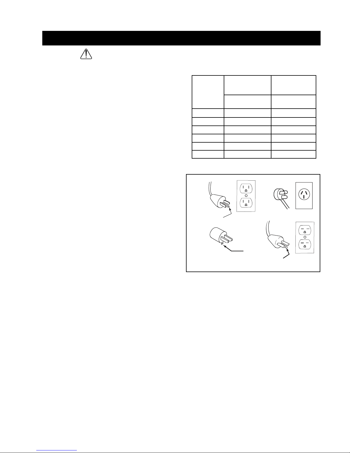
28. Safe Electrical Connection
Wet electrical connections are
shock hazards. To prevent the
cutting fluid from traveling along
the cord and contacting the plug
or power outlet, tie a drip loop as
shown. Also elevate extension
cords or gang box connections.
29. SAVE THESE INSTRUCTIONS.
22. Stay Alert
Watch what you are doing.
Use common sense.
Do not operate tool when you are tired.
Have defective switches replaced by authorized
service center.
23. Outdoor Use Extension Cords
When tool is used outdoors, use only extension
cords intended for use outdoors and so marked.

5
SAFETY SWITCH
NOTE: The Safety Switch located in the base of the unit
shuts off the motor when the unit lifts. The magnet will stay
engaged until you turn off the magnet. It is important to
keep this area clean and free from chips. Periodically check
this switch for proper function and if for some reason it is not
working properly, send the unit to an authorized repair center
for service.
SAFETY SWITCH INDICATOR LIGHT
The Safety Switch Indicator Light is a Standard Safety Feature on HMD151 magnetic drills. Its purpose
is to inform the user that an unsafe condition exists or the safety switch is defective.
If light is Green:
In normal operation the safety switch light will be green.
Motor “On” and “Off” Switches function normally.
If light is Red:
A condition with the safety switch exists that needs to be corrected.
Possible causes:
• Safety Switch is defective. Have drill serviced.
• Uneven work surface or material. Check work surface for
flatness.
• Dirt or chips under magnet. Clean work surface.
• Too thin material. Make sure material is at least 3/8” thick.
HOUGEN MANUFACTURING RECOMMENDS THAT
CONDITIONS ARE CORRECTED SO LIGHT TURNS GREEN.
THIS ALLOWS FOR THE UNIT TO BE OPERATED IN A SAFE
MANNER.
When light is Red the motor will still function, but “ON” switch
becomes a momentary switch. (The switch must be held down to
operate motor.)
For any questions please contact Hougen Manufacturing’s Technical
Service at (810) 635-7111.

6
OPERATING INSTRUCTIONS
CAUTION: Do not over-feed cutter. Excessive feed
pressure may cause the magnet to break free from
material.
DRILLING MULTIPLE LAYER MATERIALS:
**Special Cutter Geometry required
Second layer penetration may be difficult. Slight
additional feed pressure may be required (avoid over-
feed as noted above).
If unable to penetrate second layer, withdraw cutter
from material ejecting slug and clean away any
remaining chips. Feed cutter in hole and continue cut.
• Turn motor off when cut is finished.
• Fully retract cutter from material, ejecting the slug.
• Remove safety strap.
7. Turn magnet switch to “OFF” position.
CAUTION: Retain firm hold on drill to prevent
dropping.
Cutter I.D. may collect chips, restricting depth of cut.
Cutter should be frequently inspected and any chips
or debris removed.
OPTIONAL FEED METHODS:
• 5/8” Box Wrench
• Ratchet with 5/8” Socket (shown below)
• NO PLIERS OR OPEN END WRENCH (will damage
threaded feed handle mounting holes)
6. Feed Cutter slowly into workpiece. Only after cutting
path is established to a depth of about 2mm can
additional force be applied to feed handles.
Ease up on feed pressure as cutter starts
breaking through.
Rotaloc Plus™ Cutter Installation
1. Disconnect machine from power source.
2. Insert pilot into cutter.
3. Align flat on shank with pin in spindle.
4. Insert cutter into spindle.
5. Give cutter 1/4 turn in opposite direction of flutes.
1. Place drill on material and locate for drilling hole.
2. Press magnet switch to “ON”
3. Thread safety strap through opening between
motor and drill housing. Ensure that strap does
not interfere with operation of feed handles.
Insert tab of strap into buckle. Cinch strap tight to
material and drill housing. Check for slack and
adjust as needed.
CAUTION:
• Keep strap clear of cutting area, chips, and
rough edges on material.
• Inspect strap periodically for fraying and
damage. Do not use a damaged safety strap.
4. Apply liberal amount of cutting fluid or stick lubricant
to cutter. Additional lubrication may be required to
finish cut.
5. Make certain that cutter is clear of workpiece and
turn motor ON by pressing the motor START button.

PART # DESCRIPTION QTY PART # DESCRIPTION QTY
04437 Rocker Switch 1 04881 LED 1
04771 Power Cord Aus Model 1 05288 Circuit Board 1
04877 Wire Harness 1 05289 On/Off Switch 1
04878 Spacer for LED 1 17640 Power Cord 1
04879 Lens for LED 1 17689 Faceplate 1
CONTROL PANEL /HOOKUP DIAGRAM
7
From Magnet
Motor White
White from Circuit Board (P4)
Ground (Green)
LED (J3)
Safety Switch (Blue-J4)
Jumper Wires (White-J5)
Black from Circuit Board (P3)
Motor Black
Blue from Circuit Board (P2)
Brown from Circuit Board (P1)
Power In (White)
Power In (Black)
(J1)
SAFETY SWITCH LIGHT
MAGNET
R
O
T
O
M
04437 05289
04879 04878 04881 04877
04771 (HMD151Aus)
17640 (HMD151)
17689

8
23.
24.
25.
26.
10a.
10a.
27.
1.
2.
6.
5. 4.
13.
7a.
14.
7.
3.
8.
9.
12.
15.
16.
17.
18.
19.
20.
22.
10c.
10b.
39.
40.
41.
42.
43.
34.
50.
49.
35.
37.
36.
37.
45.
44.
46.
38.
47.
33.
28.
31.
11.
10.
29.
30.
32.
Torque Settings
Detent 11 150 in/lbs
Detent 12 140 in/lbs
Detent 13 45 in/lbs
Detent 14 25 in/lbs
Detent 15 15 in/lbs
Detent 28 30 in/lbs
Detent 45 15 in/lbs
Contact technical service
@ Hougen Manufacturing
for specific assembly
instructions
48.
HMD151 DRILL PARTS DIAGRAM

Item # Part # Description Qty
1 17519 Motor Assy 1
2 17693 Faceplate Assy 1
17694 Faceplate Assy Aus Model 1
3 24153 Self Tapping Screw 4
4 02547 Screw Phillips #4-40 3
5 10714 Washer Lock #4 Ext 3
6 05288 Circuit Board 1
7 17691 Electrical Box Assy 1
7A 17557 Ground Label 1
8 17274 Grommet 1
9 17293 Motor Seal 1
10 17279 Housing Assy 1
10a 17495 Bronze Bushing 2
10b 17298 Feed Gear 1
10c 40546 O-Ring 2
11 10553 Screw SHC 1/4-20 4
12 75096 Screw SHC M6 x 20mm 2
13 75094 Screw SHC M5 x 12mm 2
14 04439 Screw BHS #10-32 1
15 17476 SCR BHC Safety Torx 2
16 90052 Washer Lock #6 Ext 2
17 40374 Nut Hex #6-32 2
18 04885 Safety Switch 1
19 17271 Taper Spring 1
20 17462 Plunger 1
21 17275 Ring Retaining E Clip 1
22 17651 Magnet 1
23 17291 Screw SHC M6-1 1
Item # Part # Description Qty
24 90027 Washer SAE Flat 1
25 17282 Feed Hub Assy 1
26 17283 Feed Handle Assy 1
27 17510 Gear Cap Assy 1
28 17002 Screw SHC #6-32 7
29 17517 Thrust Washer 2
30 17516 Thrust Bearing 1
31 17502 Gear Left Hand 1
32 17278 Gear Right Hand 1
33 17646 Quill & Arbor Assy 1
34 17649 Arbor Assy 1
35 17647 Quill Assy 1
36 17546 Thrust Washer Bronze 1
37 17547 Thrust Washer Steel 2
38 04720 Retaining Ring Left Hand 1
39 17493 Screw Flat Head Mod. 1
40 17494 Plunger 1
41 17492 Compression Spring 1
42 17280 Splined Shaft 1
43 17277 Key 1/8” Square 1
44 17289 Washer Bearing Retaining 1
45 04718 Screw Pan Phillips 3
46 17475 Retaining Ring 1
47 17270 Ball Bearing 1
48 17643 Thrust Washer Shield 1
49 17644 Thrust Washer 1
50 17645 Thrust Needle Bearing 1
HMD151 PARTS LIST
9

10
Motor Diagram and Parts List
17617
17601
17618
17613
17608
17626
17609
17611
17616
17615
17605
17627
17625
Wires to Motor
Cord
17610
17603
17602
17607
17624
17623
17629
17606
17602
17632
17622
17621
17631
17604
17612
17600
Part # Description Qty Part # Description Qty
02413 Motor Cord 1 17612 Dowel Pin 1
04502 Brush Cover 2 17613 Flat Washer 1
10538 Washer #8 1 17615 Gear Housing 1
11053 BHS Screw #8-32 1 17616 Spindle 1
17294 Label, Motor 1 17617 Fan Guide 1
17537 Label, Motor Safety 1 17618 Gasket 1
17600 Field Case 1 17621 Carbon Brush (Pair) 1
17601 Gear Housing 1 17622 Brush Cap 2
17602 Ball Bearing 2 17623 Pan Head Screw 2
17603 Ball Bearing 1 17624 Pan Head Screw Short 2
17604 Ball Bearing 1 17625 Pan Head Screw Long 2
17605 Ball Bearing 1 17626 Retaining Ring 1
17606 Dust Seal 1 17627 Retaining Ring 1
17607 1st Inter. Gear Assy 1 17629 Field 1
17608 2nd Inter. Gear Assy 1 17631 Armature 1
17609 Spur Gear 1 17632 Paper Washer 2
17610 Flat Washer 1 17687 Lock Washer Heli M6 4
17611 Key 1 75150 Lock Washer Heli M5 2
75289 Pan Head Screw 2

Hougen Manufacturing, Incorporated warrants its �
from date of purchase again� This warranty is void
if the item has been damaged by accident o�
expressed warranty is given or authorized. Hougen Manufacturing, Inc. disclaims any implied warranty of MERCHANTABILITY or FITNESS for any period beyond the expressed
warranty and shall not be liable for incidental �
an implied � This warranty gives you specific legal
rights and you may also have other rights which vary from state to state.
To obtain warranty service, return the item(s), transportation prepaid, to your nearest Factory Authorized Repair Center or to Hougen Manufacturing, Inc., 3001 Hougen Drive,
Swartz Creek, Michigan 48473.
Hougen Drills (Hougen Cutters) are warranted against manufacturing defects only. Subject to Hougen Manufacturing inspection.
THIS WARRANTY IS IN LIEU OF ANY OTHER WARRANTY, EXPRESSED OR IMPLIED, INCLUDING ANY WARRANTY OF MERCHANTABILITY OR FITNESS FOR A PAR-
TICULAR PURPOSE.
© 2005 Hougen Manufacturing, Inc.
Commercial / Industrial Limited Warranty
11
19.2mm / 3/4” - D.O.C. ROTALOCTM CUTTERS
STACK CUT GEOMETRY
#TRAP EZIS
00471 mm21
20471 mm31
40471 mm41
60471 mm51
80471 mm61
01471 mm71
21471 mm81
41471 mm91
61471 mm02
81471 mm12
02471 mm22
22471 mm32
42471 mm42
52471 mm5.42
62471 mm52
82471 mm62
92471 mm5.62
03471 mm72
23471 mm82
43471 mm92
63471 mm03
83471 mm13
04471 mm23
24471 mm33
44471 mm43
64471 mm53
07471 TOLIP
#TRAP EZIS
61271 "2/1
81271 "61/9
02271 "8/5
22271 "61/11
42271 "4/3
62271 "61/31
82271 "8/7
03271 "61/51
23271 "1
43271 "61/1-1
63271 "8/1-1
83271 "61/3-1
04271 "4/1-1
24271 "61/5-1
44271 "8/3-1
07471 TOLIP
25mm / 1” - D.O.C. ROTALOC PLUSTM CUTTERS
STANDARD GEOMETRY CUTTERS
#TRAP EZIS
61171 "2/1
81171 "61/9
02171 "8/5
22171 "61/11
42171 "4/3
62171 "61/31
82171 "8/7
03171 "61/51
23171 "1
43171 "61/1-1
00171 TOLIP
#TRAP EZIS
00371 mm21
20371 mm31
40371 mm41
60371 mm51
80371 mm61
01371 mm71
21371 mm81
41371 mm91
61371 mm02
81371 mm12
02371 mm22
22371 mm32
42371 mm42
52371 mm5.42
62371 mm52
82371 mm62
92371 mm5.62
03371 mm72
00171 TOLIP
Rotaloc™ Series of Cutters for the HMD151
The ROTALOC PLUS™ cutters are made specifically for the HMD151. They are equipped with 5/8” tool-less bayonet-style
twist and lock shank. The Rotaloc Cutters are manufactured for 19.2mm / 3/4” D.O.C. The Rotoloc Plus Cutters are manu-
factured for 25mm / 1” D.O.C.
HOUGEN PATENT NOTICE
The products in this manual may be covered by one or more of the following U.S. patents, foreign patents, and pending patents:
D445808 6280123
Photographs and Specifications shown are accurate in detail at time of printing. Manufacturer reserves the right to make improvements and modifications without prior notice.
Hougen, Trak-Star, and Punch Pro are�ac-Pad
is a propriety trademark of Drillmate PTY, Ltd.
Table of contents
Other Hougen Drill manuals

Hougen
Hougen 0914104 User manual

Hougen
Hougen HMD150 SERIES User manual

Hougen
Hougen 10925 User manual

Hougen
Hougen 0905102 User manual

Hougen
Hougen 925102 User manual

Hougen
Hougen HMD115 Series User manual

Hougen
Hougen HMD918 Series User manual

Hougen
Hougen HMD904 User manual

Hougen
Hougen HMD906 Series User manual

Hougen
Hougen 10914S User manual

Hougen
Hougen HMD115 Series User manual

Hougen
Hougen HMD920 Series User manual

Hougen
Hougen HMD904 SERIES User manual

Hougen
Hougen HMD501 User manual

Hougen
Hougen HMD968 User manual

Hougen
Hougen HMD904 SERIES User manual

Hougen
Hougen 10914 User manual

Hougen
Hougen HMD505 SERIES User manual

Hougen
Hougen HMD914 series User manual

Hougen
Hougen HMD908 User manual