TCLARDEROP2
Planning Considerations
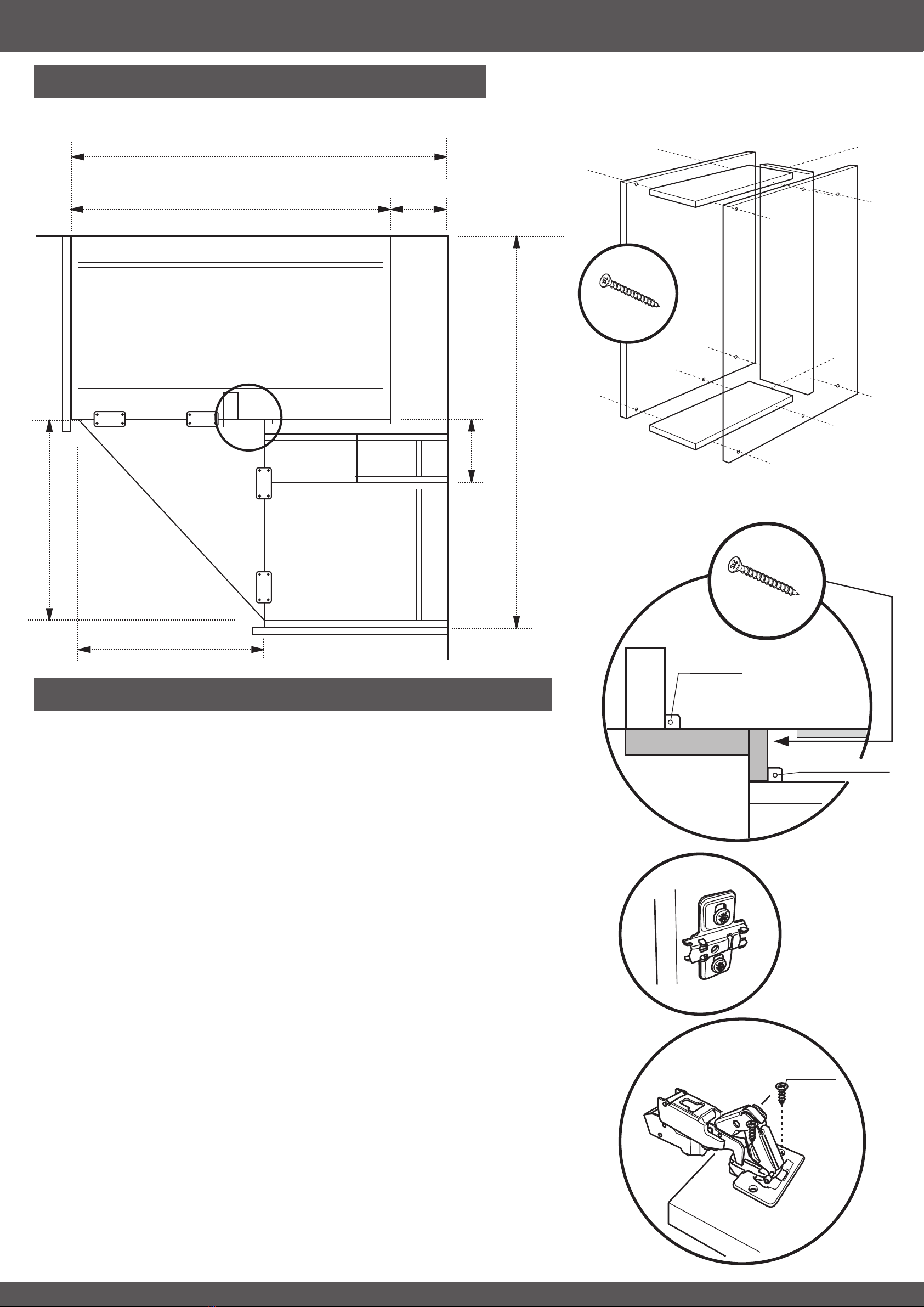
Assembly & Installation
1000mm
1161mm
161mm
Tray space box (using base decor ends)
Corner fillet/infill
1000mm Base
Wine Racks
Tray Unit
400 Larder
400 Larder Top Box
1000mm Larder Top
500 Larder Top Box
565mm
1161mm
186mm
565mm
Decor End
Decor End
Step by Step Guide
1. Using the planning considerations (Fig. A), position the 1000mm base cabinet into the corner.
Once in place secure using the wall brackets as shown in the kitchen installation manual.
2. Fit the top larder cabinet to the base cabinet and secure using the screws provided.
3. Fit the 500 larder top box to the top of the larder top using screws to secure.
4. Cut the panels to construct the corner fillet/infill panels.
5. Fit the corner fillet section to the base and larder top cabinet using KD blocks to secure (Fig. C).
6. Fit the infill panel to the fillet section using screws (Fig. C).
Note: Blanking panels (6mm) should be used top and bottom against the opening of the cabinet
which will be next to the adjoining tray space box/wine racks. Secure using screws into the front
of the cabinets. A small gap should be left so KD block fixing for the infill panel can be achieved to
the tray space box/wine racks.
7. Using base decor end panels (and the planning considerations for measurements), construct
the tray space unit using screws to secure (Fig. B).
8. Secure the wine racks and tray space to the side of the 400mm larder cabinet using screws
from the inside of the larder cabinet.
9. Fit the 400 larder top box to the top of the larder cabinet using screws to secure.
10. Fit the 400mm larder assembly to the base and larder top aligning with the infill panel. Secure
the larder to the wall and the infill to the wine rack/tray space using KD blocks.
11. Fit the decor ends to the LH & RH side of the corner larder, securing to the side panels of the
cabinets from the inside.
Note: Scribe panels to the wall as required. Ensure the decor end panels protrude the cabinets by
the thickness of the frontals being used with the unit.
12. Using a base decor end, cut the top triangular section and secure to the top of the top box
units using joining plates (Fig. A).
13. Fit the hinge plates to the LH side of the 1000mm base & larder top and the RH side of the
400mm larder unit (Fig. D).
14. Fit the 170°hinges to the doors (Fig. E).
15. Fit the doors to the cabinet and adjust (see kitchen installation manual). Use metal plates to
join the top and bottom door sections. Fit handles to the doors as required.
16. Cut the wall decor end to make two plinth sections 210mm in height. Secure these to the
bottom of each door using screws to secure (see assembly overview).
Note: Plinth sections will require ‘notching’ at the back.
Fit cornice and inner plinth sections as required.
x5/10
13mm CSK
Fig. D
Fig. E
Fig. A
Fig. B
Fig. C
KD Blocks x5
Blanking Panel
KD Blocks x5
x14
30mm
x6
30mm
104mm
37.5mm