HP Velotechnik Handrest User manual

HP V
ELOTECHNIK
GmbH & Co. KG
Kapellenstraße 49
65 30 Kriftel
Deutschland
Telefon 0 61 92 - 97 99 2-0
Telefax 0 61 92 - 97 99 2-299
E-mail mail@hpvelotechnik.com
Internet www.hpvelotechnik.com
Handauflage – Montageanleitung
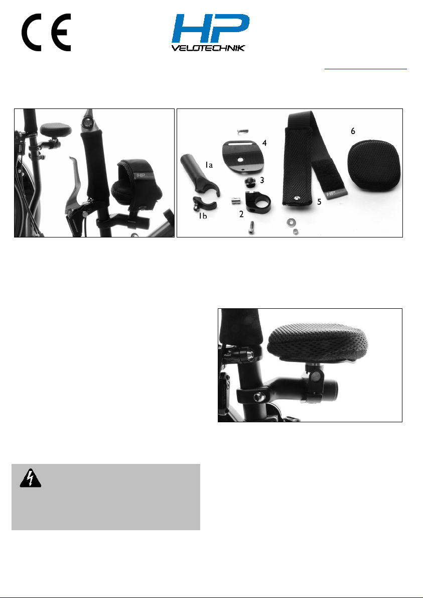
Inhalt (vormontiert)
1: Lenkerhalter (a) mit Klemmteil (b)
2: Klemmschelle, schwarz
3: Halbrundscheibe
4: Teller schwarz eloxiert
5: Halteband (je nach Ausführung)
6: Polster zum Aufkletten
- Stellblech zum aufrichten des Haltebandes
- DIN912 M5x16 A2 Zylinderschraube
- DIN7991 M6x20 A2 Senkschraube
- ISO73 0 M5x12 A2 Halbrundkopf
- Karosseriescheibe 5 auf 15 mm A2
- Hutmutter DIN917 M5 A2
- Quergewindebolzen M6, D=10mm
Die HP Velotechnik Handauflage dient als komfortable
Unterstützung der Hand auf langen Fahrten mit
Dreirädern von HP Velotechnik. Bei der Verwendung der
Handauflage mit dem Halteband ist die Fixierung einer
Hand am Lenker möglich. Der Lenkerhalter ist mit einer
geteilten Schelle ausgestattet und ermöglicht so die
Montage, ohne dass Griff, Bremshebel oder weitere
Anbauteile entfernt werden müssen.
Gefahr! Verwenden Sie den Lenkerhalter
nur zusammen mit der Handauflage. Eine
Verwendung als Lenkerverlängerung an
Aufrechtfahrrädern ist nicht zulässig,, da die
Klemmkraft hierfür nicht ausreicht.
Montage der Handauflage am Lenker:
-
Lösen Sie mit einem 5 mm Inbus-Schlüssel die Schraube
am Lenkerhalter (1a) um das Klemmteil (1b) zu
entfernen.
-
Positionieren Sie den Lenkerhalter (1a) unterhalb des
Bremsgriffs und befestigen Sie das Klemmteil (1b) so,
dass die Schraube des Lenkerhalters nach innen zeigt.
Der Lenkerhalter sollte zunächst nach hinten, leicht
nach außen gerichtet sein. Ziehen Sie die Schraube des
Lenkerhalters zunächst nur leicht an.
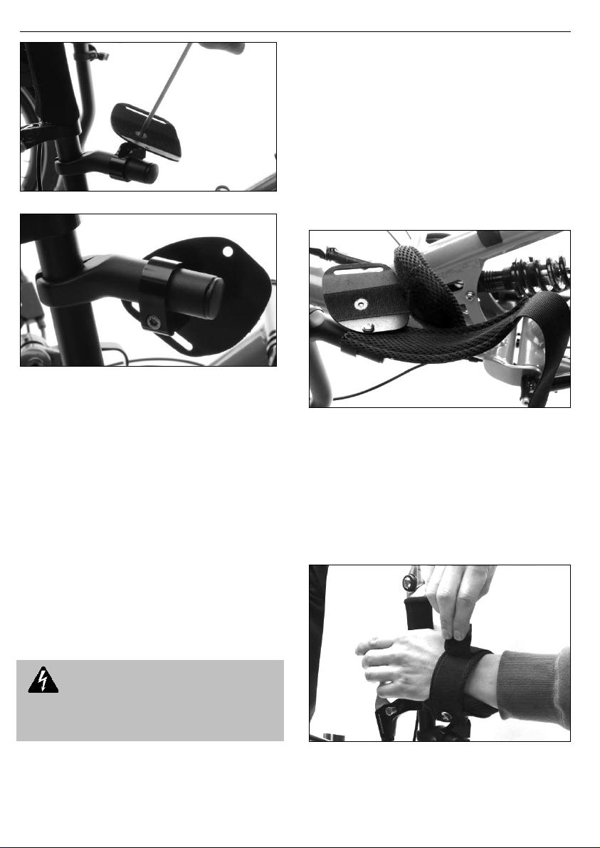
Position der rechten Handauflage am Lenker
-
Entfernen Sie das Polster der Handauflage, indem Sie es
vorsichtig vom Klett abziehen. Mit einem 4 mm Inbus-
Schlüssel können Sie die Senkschraube im Teller leicht
lösen, um diesen auszurichten. Das Langloch des
Tellers (4) der Handauflage ist nach innen gerichtet und
der Teller selbst etwa waagerecht zum Boden.
Mit einem 4 mm Inbus-Schlüssel lösen sie die
Zylinderschraube in der Klemmschelle (4), um die
Position und den Abstand zum Lenker und den seitlichen
Winkel einzustellen. Beginnen Sie mit einem Abstand von
etwa 0,5 – 1 cm vom Lenker, der Winkel sollte etwa
Wagerecht sein. Die Klemmbereich der Klemmschelle (2)
zeigt im Normalfall zur Fahrzeugmitte.

Handauflage – Montageanleitung
Version: 10/2014
Ausrichten des Tellers der Handauflage
Klemmschelle mit Befestigungsschraube M5x16
Ausrichten der Handauflage
Die Konstruktion der Handauflage bietet vielfältige
Einstellmöglichkeiten, um die Position optimal an Ihre
Haltung und die Einstellung des Fahrrades anzupassen:
Die Halbrundscheibe (3) ermöglicht das Kippen des
Tellers (4) über die Klemmschelle (2). Durch die
Befestigung mit nur einer Schraube ist es möglich, den
Teller (4) zu drehen. Drehen und Verschieben der Schelle
auf dem Lenkerhalter (1) sind weitere
Einstellmöglichkeiten.
Ziehen Sie zum Einstellen der Handauflage alle Schrauben
zunächst nur leicht fest, so dass Sie auf dem Rad sitzend
die Ausrichtung noch variieren können.
Testen Sie die Einstellung vor der Fahrt auch beim
Einlenken. Richten Sie die Lenkerhalter weiter nach außen
aus, wenn Sie beim Einlenken mit dem Sitz kollidieren.
Ziehen Sie alle Schrauben vor der Fahrt fest an!
Gefahr! Achten Sie bei der Montage darauf,
dass die Betriebssicherheit des Fahrrades nicht
beeinträchtigt wird. Der Lenkwinkel darf nicht
eingeschränkt werden.
Montage des Haltebandes
-
Entfernen Sie zunächst das Polster (6) vom Teller (4).
-
Das Halteband (5) wird mit der Halbrundkopf-Schraube
ISO73 0 M5x12A2 in der äußeren Bohrung des Tellers
(4) befestigt. Dazu führen Sie zunächst die Schraube
durch die Bohrung und setzen das Halteband (5) von
unten auf. Im Inneren des Haltebandes befindet sich ein
Federstahlblech. Achten Sie beim Montieren darauf,
dass die Schraube durch die Bohrung des
Federstahlbleches geführt wird. Setzen Sie nun die
Karosseriescheibe M5 an und verschrauben sie das
Band mit der Hutmutter.
Montage des Haltebandes am Teller
-
Führen Sie das Halteband von oben durch das Langloch
im Teller und kletten Sie das Polster mittig auf.
Schließen Sie das Halteband, indem sie Sie die Lasche mit
dem Logo greifen. Ziehen das Band leicht fest und Kletten
das freie Ende auf den Rücken des gepolsterten Teils auf.
Zum Öffnen ziehen Sie das Band vom Klett ab. Das
Halteband öffnet sich durch das Federstahlblech, so dass
Sie Ihre Hand bequem hindurchführen können.
ffnen und schließen des Haltebandes

HP V
ELOTECHNIK
GmbH & Co. KG
Kapellenstraße 49
65 30 Kriftel
Deutschland
Telefon 0 61 92 - 97 99 2-0
Telefax 0 61 92 - 97 99 2-299
E-mail mail@hpvelotechnik.com
Internet www.hpvelotechnik.com
Handrest – Mounting Instructions
ontent (pre-assembled):
1: handlebar holder (a) with clamping part (b)
2: pivot clamp for handrest
3: saddlewasher for pivot clamp
4: plate with Velcro
5: retaining strap (depending on version)
6: cushion with velcro
- strapsupport (spring steel)
- bolt DIN912 M5x16 mm, socket head
- bolt DIN7991 M6x20 mm, countersunk head
- bolt ISO73 0 M5x12 mm, round head
- large washer 5 x15 mm
- domed cap nut DIN917, M5
- cross dowel M6, D=10 mm
The HP Velotechnik Handrest provides a comfortable
hand support for long rides with trikes from HP
Velotechnik. When using with a retaining strap, the
handrest works as a fixation for one hand to the
handlebar. The handlebar holder contains a seperable
clamp that allows easy mounting without taking off the
grips, braking levers or other mounted parts from the
handlebar.
Danger! The handlebar holder must not be
used for other than mounting of the handrest The
use as a barend on other bicycles is not allowed, as
the clamping force will not be sufficent.
Mounting of the handrest:
-
Loosen the screw of the handlebar holder (1a) with a
5 mm Allen key and remove the clamping part (1b).
-
Put the handlebar holder (1a) below the braking lever
and mount the clamping part (1b) with the screw facing
inwards. The handlebar holder (1a) itself should face to
the rear, slightly turned to the outside. Tighten the
screws only to the extend so that you can move the
part later for adjustment.
Position of right handrest mounted on the handlebar
-
Remove the cushion by carefully puling it of the velcro.
With a 5 mm Allen key on the DIN7991 M6x20 mm
countersunk bolt, the plate (4) can be loosened for
adjustment. The long hole shall face to the inside, the
plate itself should be assembled in a horizontal position
in the beginning.
Use a 4mm Allen key to loosen the socket head
bolt on the pivot clamp (4) to adjust the lateral and
horizontal position on the handlebar holder. Start
with a distance of approx. 0.5 to 1.0 cm between
the plate and the handlebar, the angle should be
approximately parallel to the floor. The asymmetric

Handrest – Mounting Instructions
Version: 10/2014
pivotal clamp (2) is facing inwards in its original
position.
Adjustment of the handrest plate
Attachment bolt M5x16mm of pivotal clamp
Adjustment of the handrest:
The handrest can be adjusted perfectly to your needs in
any direction due to the multi-adjustment design with the
pivot clamp and the handlebar mount.
The saddlewasher (3) allows the tilting of the plate on the
pivot clamp (2). Rotate the pivotal clamp (2) on the
handlebar holder (1) to adjust the pitch in the other
direction. Slide the pivot clamp (2) on the handlebar
holder (1) to adjust the distance from the handlebar and
rotate the plate (4) to additionally adjust its position.
Tighten all screws only to the extend so that you can
move the parts for adjustment when you are sitting on
the bike.
Test your setup by steering to the left and to the right. If
there is any restriction by the handrest, turn the
handlebar holder (1) further to the ouside.
Tighten all screws properly before riding!
Danger! When mounting the handrest, take
care that the operating safety will not be affected.
The steering angle must not be reduced!
Mounting of the retaining strap
-
Remove the cushion (6) from the plate (4) first
-
Mount the the retaining strap (5) with the round head
bolt M5x12 in the outer hole of the plate (4). Put the
screw into the hole and place the retaining strap from
the under side. Mind the strap support sheet inside the
retaining strap: It has a hole on one side that must
mach the blank. Put the bolt through, place the large
washer and fix it with the domed cap nut DIN917 M5.
Mounting situation of the retaining strap
-
Guide the retaining strap (5) through the long hole
from the top and place the cushion (6) centered on the
the plate (4).
To open the fixation, pull the free end off from the
Velcro. The retaining strap (6) remains in the long hole so
that you can easily close it again.
The retaining strap (6) opens itself by the strap support
spring steel sheet, so that you can comfortably slide your
hand through. Close the retaining strap (6) by pulling it
on the free end with thel and attaching it on the Velcro
to the back of the strap
Opening and closing the handfixation on the handrest
Table of contents
Languages:
Other HP Velotechnik Bicycle Accessories manuals