HP Velotechnik Trikefender User manual

Achtung! Zusätzliche Bauteile wie
Rücklichter oder Reflektoren auf
dem Schutzblech können durch erhöhte
Schwingbelastung zum Bruch der Bleche
oder Halter führen. Bauen Sie keine zu-
sätzlichen Bauteile an die Schutzbleche
Ihres Fahrrades.
1
HP VELOTECHNIK GmbH & Co.KG
Kapellenstrasse 49
65830 Kriftel ●Germany
Phone +49 61 92 - 97 99 2-0
Fax +49 61 92 - 97 99 22 99
E-mail mail@hpvelotechnik.com
Internet www.hpvelotechnik.com
Montage- und Bedienungsanleitung für Trikefender
Beschreibung
Trikefender sind einseitig befestigte
Schutzbleche für die beiden Vorderräder
eines HP VELOTECHNIK Dreirades.
Sicherheitshinweise
Lesen Sie diese Montage- und Betriebs-
anleitung sorgfältig durch und bewahren Sie
sie auf. Beachten Sie auch die Fahrradanlei-
tung für Ihr Dreirad.
Gefahr! Lösen sich die Schutzbleche,
kann es zu einem Unfall und zu Verle-
tzungen kommen.Achten Sie darauf, dass
die Schutzblechhalter nach Montage der
Vorderradschutzbleche mit dem richtigen
Drehmoment (7–9 Nm) angezogen sind.
Prüfen Sie regelmäßig den festen Sitz.
Sichern Sie bei der Erstmontage und nach
jedem Lösen die Schrauben mit mittelfe-
stem Schraubenkleber (z.B. Loctite 243).
Gefahr! Schutzbleche sind einer
Schwingbeanspruchung ausgesetzt und
können dadurch brechen. Überprüfen Sie
regelmäßig den festen Sitz der
Schutzblechhalter und die Bleche auf
Rissfreiheit oder Verformungen.Tauschen
Sie beschädigten Bleche umgehend aus.
Gefahr! Verfangen sich Äste o.ä. zwi-
schen Laufrad und Schutzblech, kann
es zum Blockieren des Rades und in Folge
zu einem Unfall kommen. Halten Sie bei
ungewohnten Laufgeräuschen sofort an
und beseitigen Sie die Ursache.
Trikefender an vorn ungefederten HP Velotechnik Dreirädern Trikefender an vorn gefederten HP Velotechnik Dreirädern
Inhalt
2 Schutzbleche,2 Haltebleche,
Befestigungsmaterial
Bei Gekko fx /fx26 /fxs /26:
zusätzlich 2x Kantenschutzband
Achtung! Das Schutzblech kann
beschädigt werden, wenn das Fahrad
bei ausgebautem Vorderrad auf dem
Schutzblech abgestellt wird.Verwenden Sie
einen Montageständer.

2
Schutzblechmontage bei Scorpion fs,
/fs 26 /fs 26 Enduro /fs 26 S-Pedelec
/plus 20 /plus 26
Diese Modelle sind vorn gefedert.
Montieren Sie den Schutzblechhalter erst am
Schutzblech und dann an der Konsole des
Radträgers.Am Schutzblech zeigt der
Spritzschutz nach hinten. Richten Sie den
Schutzblechhalter so aus, dass die schmalere
Strebe nach vorne zeigt.
Mitgeliefertes Befestigungsmaterial
Positionierung des Schutzblechhalters zum Schutzblech (linkes
Schutzblech)
Positionieren Sie den Schutzblechhalter wie
beschrieben und befestigen Sie ihn mit 4
Linsenkopf-Schrauben (M5x14). Ziehen Sie
die Schrauben zunächst nur locker an, um
das Schutzblech später noch an die
Reifengröße anzupassen.
Zur Befestigung des Schutzblechs am Rad-
träger muss das Vorderrad demontiert wer-
den. Beachten Sie dazu ihre Fahrradanleitung.
Verwenden Sie die Zylinderkopfschrauben
(M6x14), um den Schutzblechhalter am
Radträger zu befestigen. Legen Sie je eine
geriffelte Sicherheitsscheibe (Schnorrschei-
be) unter die Schraubenköpfe und ziehen Sie
sie mit einem Drehmoment von 6–7 Nm an.
Montieren Sie das Vorderrad wieder am
Radträger.
Richten Sie das Schutzblech so aus, dass sich
das Rad frei drehen lässt und zwischen
Reifen und Schutzblech 10 mm Abstand blei-
ben. Es kann nötig sein, den Schutzblechhal-
ter mit einer Parallelflachzange etwas auszu-
richten, damit das Schutzblech einwandfrei
mit dem Laufrad fluchtet.
Ziehen sie alle Schrauben mit den angegeb-
nen Drehmomenten an:
Schutzblech / Schutzblechhalter 4–5 Nm
Schutzblechhalter / Radträger:6–7 Nm
Zur Befestigung gehen Sie in folgender
Reihenfolge vor.
Legen Sie je eine Cleatmutter auf der
Innenseite der Schutzblechs unter die 2
Langlöcher.Auf der Außenseite des
Schutzblechs legen Sie je 2 Dichtscheiben
mit der weichen Seite auf die Langlöcher.
Befestigung des Schutzblechhalters am Schutzblech

3
Schrauben Sie die A-Head-Kappe wieder auf.
Stellen Sie das Steuerkopflager ein. Beachten
Sie dazu die Hinweise in Ihrer Fahrradanlei-
tung.
Ziehen Sie die Klemmschelle mit 7–9 Nm
an. Richten Sie das Schutzblech so aus, daß
sich das Rad frei drehen lässt und zwischen
Reifen und Schutzblech 10 mm Abstand
bleibt. Es kann notwendig sein, den Schutz-
blechhalter mit einer Parallelflachzange
etwas auszurichten damit das Schutzblech
einwandfrei mit dem Laufrad fluchtet. Ziehen
die Schraube in der A-Head-Kappe noch
etwas fester (1–2 Nm).
Ziehen Sie die Schrauben mit den angegebe-
nen Drehmomenten an:
Schutzblech / Schutzblechhalter 4–5 Nm
Schutzblechhalter / Kappe: 1–2 Nm.
Wird ein Schutzblech dauerhaft entfernt,
muss der entnommene Spacer wieder unter
der A-Head-Kappe montiert werden.
Die Befestigung des Schutzbleches am
Schutzblechhalter erfolgt analog zur im vori-
gen Abschnitt beschriebenen Montage
(Scorpion fs usw.)
Die ringförmige Aufnahme des Schutzblech-
halters wird mit der A-head-Kappe des
Steuersatzes gegen die Klemmschelle
geklemmt.
Entfernen Sie die Schraube in der A-Head-
Kappe.Entfernen Sie den 5mm Spacer über
oder unter der Klemmschelle (dafür muss
ggf. die Klemmschelle gelöst werden).
Schrauben Sie den Gewindestift in das Ge-
winde neben der ringförmigen Aufnahme des
Schutzblechhalters, die Schraubenspitze soll
auf der Unterseite 1 bis 2mm herausragen.
Setzen Sie den Schutzblechhalter auf das
Steuerrohr so auf, dass er auf der Klemm-
schelle aufliegt. Drehen Sie die Klemmschelle
so,dass die Gewindestift in deren Klemm-
schlitz liegt. Er sichert den Schutzblechhalter
gegen Verdehen.
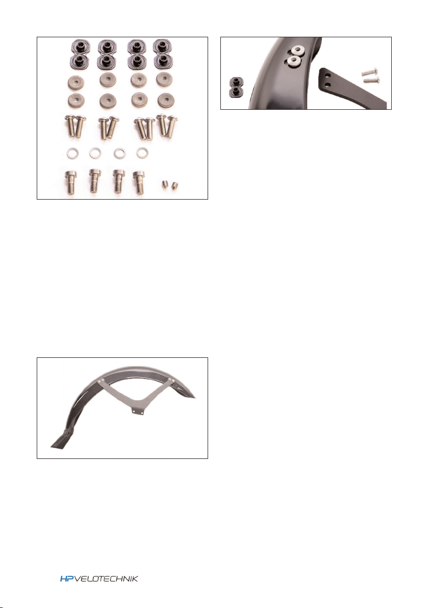
Schutzblechmontage Scorpion,
Scorpion fx, Gekko fx /fx26 /26 /fxs
Diese Modelle haben vorn keine Federung.
Montieren Sie den Schutzblechhalter zuerst
am Schutzblech.Am Schutzblech zeigt der
Spritzschutz nach hinten. Der Schutzblech-
halter wird auf das Schutzblech geschraubt.
Richten Sie den Schutzblechhalter so aus,
dass die kürzere Strebe nach vorn und die
ringförmige Aufnahme vom Schutzblech weg
zeigt.
Positionierung des Schutzblechhalters am Schutzblech (linkes
Schutzblech)

Attention! Additional parts such as
rear lights or reflectors mounted on
the mudguards may lead to cracking of the
mudguard or the mounting sheetmetal.You
should not mount additional parts to the
mudguards.
4
HP VELOTECHNIK GmbH & Co.KG
Kapellenstrasse 49
65830 Kriftel ●Germany
Phone +49 61 92 - 97 99 2-0
Fax +49 61 92 - 97 99 22 99
E-mail [email protected]
Internet www.hpvelotechnik.com
Mounting instructions for Trikefender mudguards
Description
Trikefender are single-side mounted mud-
guards for both front wheels of a HP
VELOTECHNIK trike.
Safety instructions
Carefully read this mounting instructions and
keep it. Also observe the operating manual
of your trike.
Danger! If a mudguard becomes
loose,this may lead to serious injury
or accident! Ensure that the sheet metals
are fastened to the correct tightening tor-
que (7–9 Nm) and the screws are secured
with retaining washers and thread locker
(e.g. Loctite 243). Check frequently the
assembly.
Danger! Mudguards are exposed to
very strong vibrations which may
cause them to break. Check the mountings
of the mudguards regularly for their posi-
tion and check the mudguards themselves
for cracks or deformations. Replace dama-
ged mudguards immediately.
Danger! If branches or other obsta-
cles get caught in the wheels they
may block which may lead to a serious
injury. If you hear any strange noises while
riding stop immediately and investigate the
cause.
Trikefender on non-front suspended HP Velotechnik trikes Trikefender on front supsended HP Velotechnik trikes
Content
2 mudguards, 2 mounting bracket sheetme-
tals, mounting material
for Gekko fx /fx26 /fxs /26:
additionally 2x edge guard
Attention! Front mudguards may be
damaged when the front wheel is
removed and the trike is put down on the
mudguard. Please use a work stand
instead.

5
Mudguard assembly for Scorpion fs, /fs
26 /fs 26 Enduro /fs 26 S-Pedelec /plus
20 /plus 26
These models feature front suspension.
First, mount the mounting bracket sheetme-
tal to the mudguard.Then, mount the assem-
bly to the suspension strut’s console.The
splash guard faces backwards.The narrower
stay of the bracket is forward.
Included mounting material
Position of the mounting bracket in respect to the mudguard
(left side part)
Position the mounting bracket as described
and fix it to the mudguard using 4 mush-
room head screws (M5x14). Do not tighten
the screws to make adjustment possible.
To mount the mudguard to the suspension
strut the front wheel has to be removed.
Please refer to the trike’s operating manual.
Use 2 socket head screws M6x14 to fix the
mudguard to the suspension strut’s console.
Put a safety washer (Schnorr washer) under
each screwhead.Tighten the screws with
6–7 Nm.
Reassemble the front wheel.
Adjust the mudguard.The wheel must rotate
freely.There must be a minimum distance of
10 mm between tire and mudguard. It may
be necessary to align the mounting brackets
with a pliers wrench align it with the wheel.
Tighten all screws:
Mudguard / mounting bracket: 4–5 Nm
Mounting bracket / susp.strut: 6–7 Nm
Assemble the mudguard to the mounting
bracket sheetmetal:
Put a one cleat nut on the inside of the
mudguard on each of the two long holes.
On the outside,position a sealing washers
on each of the long holes (soft side faces
the mudguard).
Mounting the bracket to the mudguard

6
Put on the A-head cap and insert its screw.
To adjust the headset, refer to the trike’s
operating manual.
Tighten the clamp with 7–9 Nm.Adjust the
mudguard.The wheel must rotate freely.
There must be a minimum distance of 10
mm. It may be necessary to align the moun-
ting brackets with a pliers wrench align it
with the wheel.Tighten the A-head cap
screw with 1–2 Nm.
Tighten all screws:
Mudguard / mounting bracket: 4–5 Nm
Mounting bracket / cap: 1–2 Nm
In case the mudguards are removed, the spa-
cer must be reinstalled under the A-head
cap.
Assembling the mudguard to the mounting
bracket is done as described in the prede-
cessing paragraph (Scorpion fs etc.)
The mounting hole of the sheetmetal brak-
ket is clamped under the A-head cap of the
headset.
Unscrew the screw in the A-head cap.
Remove the A-head cap and the 5 mm spa-
cer above or beneath the clamp (open and
remove the clamp if necessary). Insert the
set screw into the small threaded hole next
to the mounting hole.The tip should protru-
de for 1 or 2 mm. Put the mounting bracket
on the knuckle’s steerer until it rests on the
clamp.The clamp is swivelled until the tip of
the set screw is located in the clamping slot.
It prevents the mounting bracket from rota-
ting.
Mudguard assembly for Scorpion,
Scorpion fx, Gekko fx /fx26 /26 /fxs
These models feature no front suspension.
First, mount the mounting bracket sheetme-
tal to the mudguard.The splash guard faces
backwards.The shorter stay of the bracket is
forward.The mounting hole faces away from
the mudguard.
Position of the mounting bracket in respect to the mudguard
(left side part)
set screw
Table of contents
Languages:
Other HP Velotechnik Bicycle Accessories manuals
Popular Bicycle Accessories manuals by other brands

CAMPAGNOLO
CAMPAGNOLO Record 10S manual

e-bike vision
e-bike vision 10040 Manual/Safety Notes

Landscape Fusion
Landscape Fusion F1178 Assembly instructions

Xplova
Xplova X2 user manual

Cannondale
Cannondale LEFTY SPEED DLR2 Owner's manual supplement

Evotech Performance
Evotech Performance PRN014568-014925 installation instructions

Ardi Technology
Ardi Technology BIKE GUARD 708A3 PLUS user manual

Digital Telecom Technology Limited
Digital Telecom Technology Limited Elkfit Cycler C01 user manual

CORIMA
CORIMA ESSENTIA 40 User instruction

Shimano
Shimano CS-HG40 - SCHEMA manual

Tailfin
Tailfin AeroPack Assembly instructions

SP CONNECT
SP CONNECT STEM MOUNT PRO Mounting instructions