manuals.online logo
Brands
  1. Home
  2. •
  3. Brands
  4. •
  5. HP
  6. •
  7. Antenna
  8. •
  9. HP J9659A User manual

HP J9659A User manual

Other HP Antenna manuals

HP J9170A User manual

HP

HP J9170A User manual

HP ProCurve J8441A User manual

HP

HP ProCurve J8441A User manual

HP J9659A User manual

HP

HP J9659A User manual

HP J8134A Assembly instructions

HP

HP J8134A Assembly instructions

HP ProCurve J8445A User manual

HP

HP ProCurve J8445A User manual

HP 8445B Operation manual

HP

HP 8445B Operation manual

HP J9720A User manual

HP

HP J9720A User manual

HP ProCurve J9169A User manual

HP

HP ProCurve J9169A User manual

HP ProCurve Networking J9000A User manual

HP

HP ProCurve Networking J9000A User manual

HP J8999A User manual

HP

HP J8999A User manual

HP ProCurve J8444A User manual

HP

HP ProCurve J8444A User manual

HP ProCurve 2 dBi Assembly instructions

HP

HP ProCurve 2 dBi Assembly instructions

Popular Antenna manuals by other brands

DAVIS Windex AV 3160 installation instructions

DAVIS

DAVIS Windex AV 3160 installation instructions

Belden Hirschmann BAT-ANT-N-14G-IP23 Mounting instruction

Belden

Belden Hirschmann BAT-ANT-N-14G-IP23 Mounting instruction

Vtronix YHK Fitting instructions

Vtronix

Vtronix YHK Fitting instructions

KVH Industries TracVision 6 Technical manual

KVH Industries

KVH Industries TracVision 6 Technical manual

Leica Geosystems GS10 user manual

Leica Geosystems

Leica Geosystems GS10 user manual

Sirio Antenne Gain-Master manual

Sirio Antenne

Sirio Antenne Gain-Master manual

Sony VCA-41 Installation/connections

Sony

Sony VCA-41 Installation/connections

ZCG Y100 Series installation guide

ZCG

ZCG Y100 Series installation guide

Advantech Wireless INTREPID120 Assembly instructions

Advantech Wireless

Advantech Wireless INTREPID120 Assembly instructions

Cerio ANT-10AO installation guide

Cerio

Cerio ANT-10AO installation guide

Alfa Network APA-L01 Specifications

Alfa Network

Alfa Network APA-L01 Specifications

Naval PR-422CA Operation manual

Naval

Naval PR-422CA Operation manual

Feig Electronic ID ISC.ANTH200/200 Series manual

Feig Electronic

Feig Electronic ID ISC.ANTH200/200 Series manual

TERK Technologies TV44 owner's manual

TERK Technologies

TERK Technologies TV44 owner's manual

TERK Technologies SIR3 owner's manual

TERK Technologies

TERK Technologies SIR3 owner's manual

Directive Systems & Engineering DSE2324LYRMK quick start guide

Directive Systems & Engineering

Directive Systems & Engineering DSE2324LYRMK quick start guide

MobilSat MSP-S Mounting instructions

MobilSat

MobilSat MSP-S Mounting instructions

Steren ANT-UHF 13 instruction manual

Steren

Steren ANT-UHF 13 instruction manual

manuals.online logo
manuals.online logoBrands
  • About & Mission
  • Contact us
  • Privacy Policy
  • Terms and Conditions

Copyright 2025 Manuals.Online. All Rights Reserved.

HP 2.5/6 dBi Dual-Band 6-Element MIMO Omni Directional Antenna (J9659A) Guide
SAFETY
The HP J9659A antenna and all associated equipment should be
installed in accordance with all applicable local and national electrical
code guidelines to ensure safe operation.
Before connecting an external antenna to an HP Wireless Access
Point, be sure that the access point radio power levels are set in
accordance with local regulatory requirements. For information on
setting radio power levels, see Transmit power control in the
MSM3xx/4xx Access Points Management and Configuration Guide.
For mandatory antenna power settings by country/region, look for
Antenna Power-Level Setting Guide (for MSM products) at
www.hp.com/networking/support.
Please read all instructions carefully before attempting to
install and use this product.
Grounding: Proper system grounding is essential.
SPECIFICATIONS
WARRANTY AND SUPPORT INFORMATION
See the warranty and support information included with this product. For
the latest information, go to www.hp.com/networking/support.
DESCRIPTION
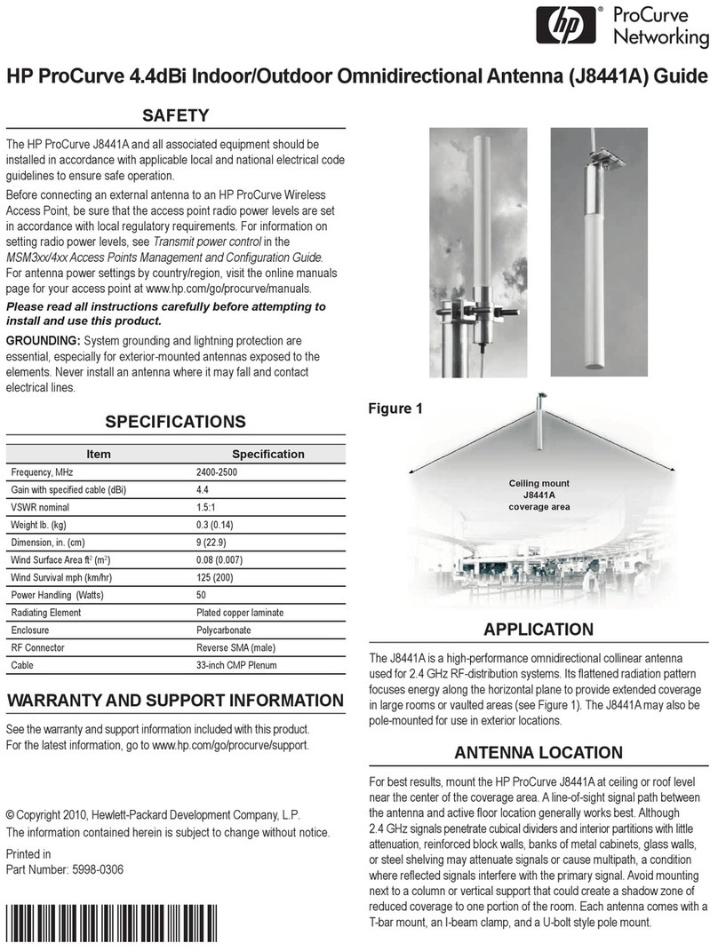
The HP J9659A is an indoor ceiling grid-mounted omnidirectional
array especially designed for use with dual-radio 802.11n access
points. Six independent vertically polarized radiators provide
omnidirectional coverage for meeting rooms, offices, departmental
areas, or other enclosed spaces.
ANTENNA LOCATION
For best results, mount the HP J9659A at ceiling level near the center
of the coverage area. A line-of-sight path between the antenna and
active floor locations works best. Avoid mounting next to a column or
vertical support that could create a shadow zone and reduce coverage
to a portion of the room.
INSTALLATION
Item Specification
Frequency 2.4-2.5 GHz & 5.15-5.85 GHz
Gain with 33” cable (dBi) 2.5 dBi @ 2.4 GHz and 5.9 dBi @ 5 GHz
VSWR Maximum 2:1
3 dB Beamwidth – Azimuth Omnidirectional
3 dB Beamwidth – Elevation 75°: 2.4-2.5/45°: 5.15-5.85
Polarization Linear 6 Vertical
Maximum Input Power 5 Watts
Cable Length in. (mm) 33” (838.2 mm) Plenum rated
Mechanical Size in. (mm) 8.6” x 1.7” (219 x 44 mm)
Weight 1.5 lb. (0.7 kg)
Antenna Connection RP-SMA (6x)
Radome Enclosure ASA
Mount Style Ceiling Grid/Suspended Tile
Figure 1
© Copyright 2010, Hewlett-Packard Development Company, L.P.
The information contained herein is subject to change without notice.
Printed in Malaysia
November 2010
Document Part Number: 5998-0931
*5998-0931*
2 HP 2.5/6 dBi Dual-Band 6-Element MIMO Omni Directional Antenna (J9659A) Guide
A threaded post on the back of the antenna and a supplied mounting
nut are the primary mounting method when access is available to both
sides of the mounting surface, such as a suspended ceiling tile. Mark
the desired mounting location on the tile and cut a 40mm (1.57”) hole.
Feed the cables through the hole and secure the antenna with the
mounting nut. The included rubber locking gasket should only be used
with the mounting nut when mounting to a hard surface. If access to
the back of the mounting surface is limited, there are two mounting
holes that can be used with #8 screws and expanding anchors (not
supplied).
Connect the three blue antenna leads to an AP radio configured for
5 GHz and connect the three black antenna leads to an AP radio
configured for 2.4 GHz.
ANTENNA PATTERN PLOTS
The plots are oriented as follows:
E0 Plane 270
E0 Plane 90
H Plane 0
E90 Plane 90
H Plane 90
E90 Plane 0
H Plane 180
E90 Plane 270
E0 Plane 180
E0 Plane 0
E90 Plane 180
H Plane 270
Plot Orientation Diagram
320
310
300
290
280
270
260
250
240
230
220
0
350
340
330
210
200
190 180 170
160
150
140
130
120
110
100
90
80
70
60
50
40
30
20
10
-20 -10 0
dB
2.45 GHz
H Plane E0 Plane E90 Plane
5.47 GHz
H Plane E0 Plane E90 Plane
320
310
300
290
280
270
260
250
240
230
220
0
350
340
330
210
200
190 180 170
160
150
140
130
120
110
100
90
80
70
60
50
40
30
20
10
-20 -10 0
dB
5.725 GHz
H Plane E0 Plane E90 Plane
320
310
300
290
280
270
260
250
240
230
220
0
350
340
330
210
200
190 180 170
160
150
140
130
120
110
100
90
80
70
60
50
40
30
20
10
-20 -10 0
dB