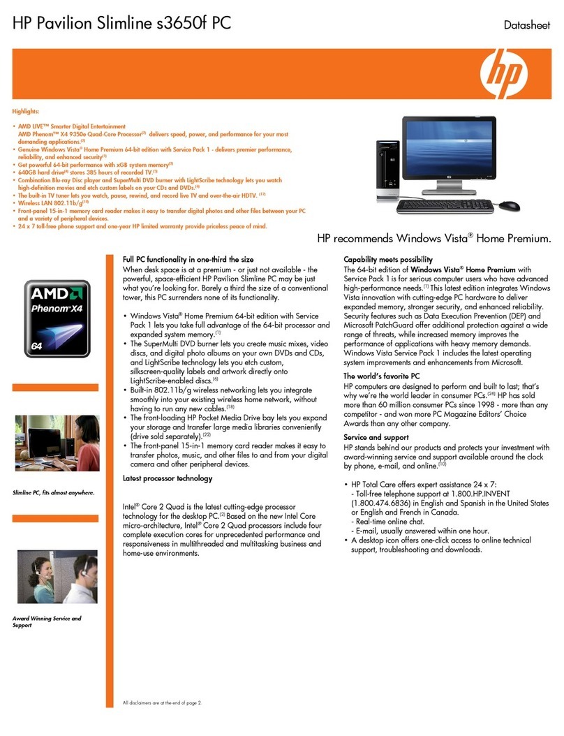
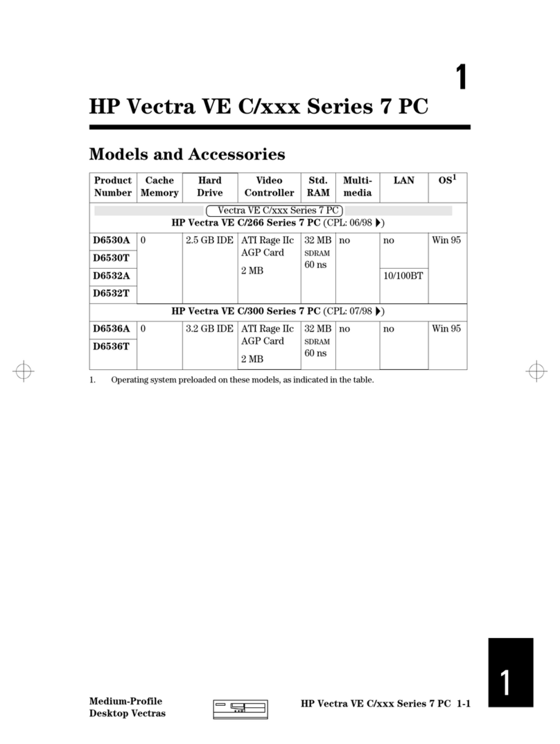
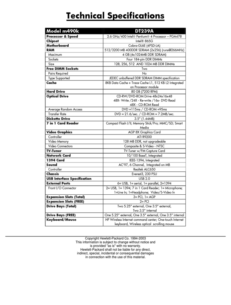
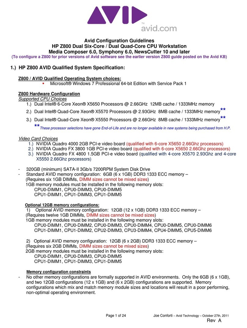
manuals.online logo
Brands
  1. Home
  2. •
  3. Brands
  4. •
  5. HP
  6. •
  7. Desktop
  8. •
  9. HP Z2 Mini G5 Assembly instructions

HP Z2 Mini G5 Assembly instructions

EL-MF877-00 Page 1
Template Revision C
Last revalidation date 04-01-2018
HPI instructions for this template are available at EL-MF877-01
Product End-of-Life Disassembly Instructions
Product Category: Workstations
Marketing Name / Model
[List multiple models if applicable.]
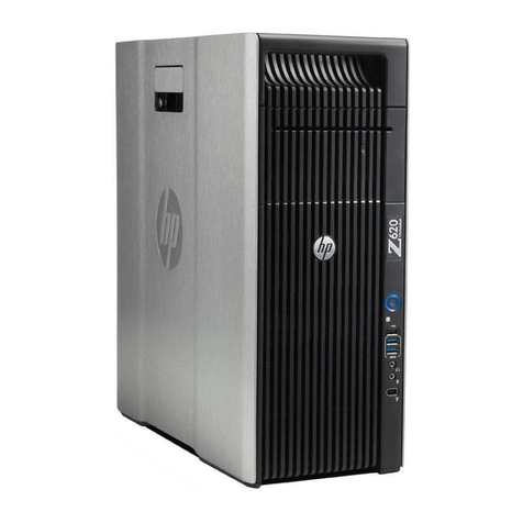
HP Z2 Mini G5 Workstation
TPC-I046-DM-180
TPC-I046-DM-280
Purpose: The document is intended for use by end-of-life recyclers or treatment facilities. It provides the basic instructions for the
disassembly of HPI products to remove components and materials requiring selective treatment, as defined by EU directive
2002/96/EC, Waste Electrical and Electronic Equipment (WEEE).
NOTE: Recyclers should sort plastic materials into resin streams for recycling based on the ISO 11469 plastic marking code on the
plastic part. For any questions on plastic marking, please contact HP’s Sustainability Contact.
1.0 Items Requiring Selective Treatment
1.1 Items listed below are classified as requiring selective treatment.
1.2 Enter the quantity of items contained within the product which require selective treatment in the right column, as applicable.
Item Description Notes
Quantity of
items
included in
product
Printed Circuit Boards (PCB) or Printed Circuit
Assemblies (PCA)
With a surface greater than 10 sq cm
6
Batteries, excluding Li-Ion batteries.
All types including standard alkaline, coin or button style
batteries
1
Li-Ion batteries. Include all Li-Ion batteries if more than
one is provided with the product (such as a detachable
notebook keyboard battery, RTC coin cell, etc.)
Battery(ies) are attached to the product by (check all
that apply with an “x” inside the “[ ]”):
[0 ] screws
[0 ] snaps
[ ] adhesive
[ ] other. Explain
NOTE: Add detailed removal procedures including
required tools in the sections 3.1/3.2.
0
Mercury-containing components For example, mercury in lamps, display backlights,
scanner lamps, switches, batteries
0
Liquid Crystal Displays (LCD) with a surface greater than
100 sq cm
Includes background illuminated displays with gas
discharge lamps (15.6”)
0
Cathode Ray Tubes (CRT)
0
Capacitors / condensers (Containing PCB/PCT)
0
Electrolytic Capacitors / Condensers measuring greater
than 2.5 cm in diameter or height
0
External electrical cables and cords
DC Cable for External Power Supply
1
Gas Discharge Lamps
0
EL-MF877-00 Page 2
Template Revision C
Last revalidation date 04-01-2018
HPI instructions for this template are available at EL-MF877-01
Item Description Notes
Quantity of
items
included in
product
Plastics containing Brominated Flame Retardants
weighing > 25 grams (not including PCBs or PCAs
already listed as a separate item above)
Components and parts containing toner and ink,
including liquids, semi-liquids (gel/paste) and toner
Include the cartridges, print heads, tubes, vent
chambers, and service stations.
0
Components and waste containing asbestos
0
Components, parts and materials containing refractory
ceramic fibers
0
Components, parts and materials containing
radioactive substances
0
2.0 Tools Required
List the type and size of the tools that would typically be used to disassemble the product to a point where components and
materials requiring selective treatment can be removed.
Tool Description
Tool Size (if
applicable)
Screw driver
T8
Screw driver
T10
Screw driver
T15
3.0 Product Disassembly Process
3.1 List the basic steps that should typically be followed to remove components and materials requiring selective treatment
including the required steps to remove the external enclosure:
1. Follow steps described in Disassembly instruction (file attached)
2. If parts can be removed without using a tool, remove it first
3. Use correct screwdriver and torque value before unlock the screw
4.
5.
6.
3.2 Optional Graphic. If the disassembly process is complex, insert a graphic illustration below to identify the items contained in the
product that require selective treatment (with descriptions and arrows identifying locations).
EL-MF877-00 Page 3
Template Revision C
Last revalidation date 04-01-2018
HPI instructions for this template are available at EL-MF877-01
MANUFACTURING PROCESS INSTRUCTIONS
MECHANICAL ASSEMBLY
MODEL :Ludao
Tabulation:Zhou. Guilin
Review:Zhao. Cheng yang
0.20
Station Version Station Version Station Version Station Version Station Version Station Version
1 0.20 9 0.20 17 0.20
2 0.20 10 0.20 18 0.20
3 0.20 11 0.20 19 0.20
4 0.20 12 0.20
5 0.20 13 0.20
6 0.20 14 0.20
7 0.20 15 0.20
8 0.20 16 0.20
Station
Ver.
ALL 0.1*
ALL 0.20
The first disassembly SOP
kou.xiangqin
2020/5/13
2020/7/1
add remove the M/B battery whole updating
kou.xiangqin
2020/7/1
Design
1 of 27
Page:
Content
Date
Sub-assembly name:
Ludao disassembly SOP
Document No.:
Ludao disassembly SOP
A.Current station version list:
B.Version Modify list:
Written by:
Zhou. Guilin
Revision:
Date:
Document No. : Ludao disassembly SOP station :
Operation Name : Ver. : Edit date
Step:
Standard Operation Procedure
Notice: Please inform production line leader or master if you found any abnormal..
Fixture list (Spec.) Qty Symbol
Safe Order Hear Look manu
al Static
Qual
ity
Fix
tur
e
Issue Department:
Lister:Zhou. Gui-lin Industrial Engineering Class
Disassemble top cover
Half finger insert 1
1(1/1)
1. Press the detachable button to the right to pop out the top cover;(pic1)
2.Lift the top cover and take it out in the oblique direction;(pic2)
Lift the top cover and take it out in the oblique direction
Press the detachable button to the right
Pic1
Pic2
2020/7/1
0.20
Document No. : Ludao disassembly SOP station :
Operation Name : Ver. : Edit date
Step:
Standard Operation Procedure
Notice: Please inform production line leader or master if you found any abnormal..
Fixture list (Spec.) Qty Symbol
Safe Order Hear Look manu
al Static
Qual
ity
Fix
tur
e
Issue Department:
Lister:Zhou. Gui-lin Industrial Engineering Class
Disassemble HDD
Half finger insert 1
2(1/2)
1. Disassemble the HDD set screw*1(Pic1)
the torque force of the driver is 2.5+/-0.2kgf.cm
2.Take out the HDD in the oblique direction(Pic2)
3.Disassemble HDD and HDD cable(Pic3)
the HDD cable shall be pulled out horizontally
For HDD SKU
Pic1
T8 electric screw driver 1
pulled out horizontally
Take out the HDD in the oblique direction
Pic2
Pic3
2020/7/1
0.20
Document No. : Ludao disassembly SOP station :
Operation Name : Ver. : Edit date
Step:
Standard Operation Procedure
Notice: Please inform production line leader or master if you found any abnormal..
Fixture list (Spec.) Qty Symbol
Safe Order Hear Look manu
al Static
Qual
ity
Fix
tur
e
Issue Department:
Lister:Zhou. Gui-lin Industrial Engineering Class
2(2/2)
For no HDD SKU
Pic1
Pic2
1. Disassemble the HDD set screw*1(Pic1)
the torque force of the driver is 2.5+/-
0.2kgf.cm
2.Take out the HDD in the oblique direction
(Pic2)
Disassemble HDD
Take out the HDD in the oblique direction
Half finger insert 1
T8 electric screw driver 1
2020/7/1
0.20
Document No. : Ludao disassembly SOP station :
Operation Name : Ver. : Edit date
Step:
Standard Operation Procedure
Notice: Please inform production line leader or master if you found any abnormal..
Fixture list (Spec.) Qty Symbol
Safe Order Hear Look manu
al Static
Qual
ity
Fix
tur
e
Issue Department:
Lister:Zhou. Gui-lin Industrial Engineering Class
Disassemble HDD screw
3(1/1)
1. Remove the side screws of the HDD set
after putting it into the fixture(pic1)
the torque force of the driver is 2.5+/-
0.2kgf.cm
For no HDD SKU
pic1
pic2
For HDD SKU
1. Remove the screws of the HDD set after
putting it into the fixture(pic2)
the torque force of the driver is 2.5+/-
0.2kgf.cm
Half finger insert 1
T10 electric screw driver 1
2020/7/1
0.20
Document No. : Ludao disassembly SOP station :
Operation Name : Ver. : Edit date
Step:
Standard Operation Procedure
Notice: Please inform production line leader or master if you found any abnormal..
Fixture list (Spec.) Qty Symbol
Safe Order Hear Look manu
al Static
Qual
ity
Fix
tur
e
Issue Department:
Lister:Zhou. Gui-lin Industrial Engineering Class
Disassemble CPU fan、GPU fan
4(1/1)
1. Lift the fan(pic1)
2. Take the fan connector.(pic2)
3. Take the fan(pic3)
Tap the fan hook on either side
pic1
pic2
pic3
Half finger insert 1
2020/7/1
0.20
Document No. : Ludao disassembly SOP station :
Operation Name : Ver. : Edit date
Step:
Standard Operation Procedure
Notice: Please inform production line leader or master if you found any abnormal..
Fixture list (Spec.) Qty Symbol
Safe Order Hear Look manu
al Static
Qual
ity
Fix
tur
e
Issue Department:
Lister:Zhou. Gui-lin Industrial Engineering Class
Disassemble CPU/GPU thermal
5(1/1)
1. Take CPU thermal module/GPU module screws
(pic1/pic2);
when taking the screw,align the driver head
first and then turn the electric driver to prevent
the main screw from sliding.
the torque force of the driver is 2.5+/-0.2kgf.cm
1
2
3
4
pic1 pic2
Half finger insert 1
T15 electric screw driver 1
2020/7/1
0.20
Document No. : Ludao disassembly SOP station :
Operation Name : Ver. : Edit date
Step:
Standard Operation Procedure
Notice: Please inform production line leader or master if you found any abnormal..
Fixture list (Spec.) Qty Symbol
Safe Order Hear Look manu
al Static
Qual
ity
Fix
tur
e
Issue Department:
Lister:Zhou. Gui-lin Industrial Engineering Class
Disassemble VGA/B
1.Take MXM screws,take MXM card (pic1)
the torque force of the driver is 1.5+/-
0.2kgf.cm
when taking the screw,align the driver
head first and then turn the electric driver
6(1/2)
pic1
For 125W
1
2
Half finger insert 1
#1 electric screw driver 1
2020/7/1
0.20
Document No. : Ludao disassembly SOP station :
Operation Name : Ver. : Edit date
Step:
Standard Operation Procedure
Notice: Please inform production line leader or master if you found any abnormal..
Fixture list (Spec.) Qty Symbol
Safe Order Hear Look manu
al Static
Qual
ity
Fix
tur
e
Issue Department:
Lister:Zhou. Gui-lin Industrial Engineering Class
Disassemble Thermal sponge
1. Take sponge(pic1)
6(2/2)
pic1
For 65W
pic2
1. Take sponge(pic2)
For 125W
2020/7/1
0.20
Document No. : Ludao disassembly SOP station :
Operation Name : Ver. : Edit date
Step:
Standard Operation Procedure
Notice: Please inform production line leader or master if you found any abnormal..
Fixture list (Spec.) Qty Symbol
Safe Order Hear Look manu
al Static
Qual
ity
Fix
tur
e
Issue Department:
Lister:Zhou. Gui-lin Industrial Engineering Class
Disassemble serial/B
1. Disassemble serial/b screws*2
(pic1)
the torque force of the driver is
1.5+/-0.2kgf.cm
when taking the screw,align
the driver head first and then
turn the electric driver
2.Take cable(pic2)
7(1/2)
pic1
pic2
For serial/B SKU
Half finger insert 1
#1 electric screw driver 1
2020/7/1
0.20
Document No. : Ludao disassembly SOP station :
Operation Name : Ver. : Edit date
Step:
Standard Operation Procedure
Notice: Please inform production line leader or master if you found any abnormal..
Fixture list (Spec.) Qty Symbol
Safe Order Hear Look manu
al Static
Qual
ity
Fix
tur
e
Issue Department:
Lister:Zhou. Gui-lin Industrial Engineering Class
Disassemble USB/B
1. Take USB/B set screws*2(pic1)
the torque force of the driver is 1.5+/-
0.2kgf.cm
2.Take FFC from the M/B connector(pic2)
7(2/2)
pic1 pic2
For USB/B SKU
Drive the piano cover
industry ,and then pull
the USB FFC straight
Half finger insert 1
#1 electric screw driver 1
2020/7/1
0.20
Document No. : Ludao disassembly SOP station :
Operation Name : Ver. : Edit date
Step:
Standard Operation Procedure
Notice: Please inform production line leader or master if you found any abnormal..
Fixture list (Spec.) Qty Symbol
Safe Order Hear Look manu
al Static
Qual
ity
Fix
tur
e
Issue Department:
Lister:Zhou. Gui-lin Industrial Engineering Class
Disassemble TBT/B
1. Take the screws*2(pic1)
the torque force of the driver is 1.5+/-
0.2kgf.cm
2. Take out the TBT vertically upward;
(pic2)
When taking out the TBT from the
middle frame,do not shake from left
to right to prevent the TBT BRK surface
from scraping off the patient.
8(1/2)
pic1
M2 screw
pic2
For TBT SKU
Half finger insert 1
#1 electric screw driver 1
2020/7/1
0.20
Document No. : Ludao disassembly SOP station :
Operation Name : Ver. : Edit date
Step:
Standard Operation Procedure
Notice: Please inform production line leader or master if you found any abnormal..
Fixture list (Spec.) Qty Symbol
Safe Order Hear Look manu
al Static
Qual
ity
Fix
tur
e
Issue Department:
Lister:Zhou. Gui-lin Industrial Engineering Class
Disassemble Hood sensor
8(2/2)
1. Take the housing from the middle body(pic1)
2. Take cable CNTR (pic2)
pic1
pic2
For Hood sensor SKU
2、pull out the right hook with the torque
1、take housing left hook to the right to popup
Half finger insert 1
2020/7/1
0.20
Document No. : Ludao disassembly SOP station :
Operation Name : Ver. : Edit date
Step:
Standard Operation Procedure
Notice: Please inform production line leader or master if you found any abnormal..
Fixture list (Spec.) Qty Symbol
Safe Order Hear Look manu
al Static
Qual
ity
Fix
tur
e
Issue Department:
Lister:Zhou. Gui-lin Industrial Engineering Class
Disassemble HDD cable
9(1/2)
pic1
For HDD SKU
1. Take HDD cable connector.(pic1 )
Half finger insert 1
2020/7/1
0.20
Document No. : Ludao disassembly SOP station :
Operation Name : Ver. : Edit date
Step:
Standard Operation Procedure
Notice: Please inform production line leader or master if you found any abnormal..
Fixture list (Spec.) Qty Symbol
Safe Order Hear Look manu
al Static
Qual
ity
Fix
tur
e
Issue Department:
Lister:Zhou. Gui-lin Industrial Engineering Class
Take DDR & shielding can
1. Take shielding can*1(pic1)
Take shielding can both side black mylar
and then pull straight up at the same time.
2. Take DDR(pic2)
Open the DDR connector arm to both sides
and pop out the DDR in the oblique
direction
3. Take absorbing material*1(pic3)
9(2/2)
pic2
pic1
pic3
Half finger insert 1
2020/7/1
0.20
Document No. : Ludao disassembly SOP station :
Operation Name : Ver. : Edit date
Step:
Standard Operation Procedure
Notice: Please inform production line leader or master if you found any abnormal..
Fixture list (Spec.) Qty Symbol
Safe Order Hear Look manu
al Static
Qual
ity
Fix
tur
e
Issue Department:
Lister:Zhou. Gui-lin Industrial Engineering Class
Disassemble SSD
10(1/1)
1. Take SSD screws and take the SSD(pic1)
the torque force of the driver is 1.5+/-
0.2kgf.cm
when taking the screw,align the driver
head first and then turn the electric
driver
2. Break the ILM connecting rod,lift the
iron,and assemble the CPU ILM cover
(pic2、pic3)
pic1
pic2 pic3
Half finger insert 1
#1 electric screw driver 1
2020/7/1
0.20
Document No. : Ludao disassembly SOP station :
Operation Name : Ver. : Edit date
Step:
Standard Operation Procedure
Notice: Please inform production line leader or master if you found any abnormal..
Fixture list (Spec.) Qty Symbol
Safe Order Hear Look manu
al Static
Qual
ity
Fix
tur
e
Issue Department:
Lister:Zhou. Gui-lin Industrial Engineering Class
Disassemble CPU
1. Using a fixture to clamp the CPU to
place the tray(pic1/pic2)
2. Bake to the connecting rod
disassemble the CPU must use the fixture
11(1/1)
CPU triangle symbol and
fixture triangle symbol in
the same direction
pic2
Fixture boss facing
into the plate
CPU assemble fixture 1
pic1
Half finger insert 1
2020/7/1
0.20

This manual suits for next models

2

Other HP Desktop manuals

HP Pavilion a6230 User manual

HP

HP Pavilion a6230 User manual

HP dx2310 - Microtower PC Setup guide

HP

HP dx2310 - Microtower PC Setup guide

HP TouchSmart 600-1300 - Desktop PC Parts list manual

HP

HP TouchSmart 600-1300 - Desktop PC Parts list manual

HP Z1 G3 Manual

HP

HP Z1 G3 Manual

HP Compaq Presario Manual

HP

HP Compaq Presario Manual

HP EliteDesk 705 G1 User manual

HP

HP EliteDesk 705 G1 User manual

HP Pro 3330 Setup guide

HP

HP Pro 3330 Setup guide

HP Xw4300 - Workstation - 2 GB RAM User instructions

HP

HP Xw4300 - Workstation - 2 GB RAM User instructions

HP Z200 - Small Form Factor Workstation Reference guide

HP

HP Z200 - Small Form Factor Workstation Reference guide

HP DB252A User manual

HP

HP DB252A User manual

HP 425s User manual

HP

HP 425s User manual

HP Compaq dc7900 Small Form Factor Business Assembly instructions

HP

HP Compaq dc7900 Small Form Factor Business Assembly instructions

HP DL320 - ProLiant - G3 Operating and safety instructions

HP

HP DL320 - ProLiant - G3 Operating and safety instructions

HP 280 G2 MT Business Manual

HP

HP 280 G2 MT Business Manual

HP Media Center Manual

HP

HP Media Center Manual

HP D7171A - NetServer - LPr User manual

HP

HP D7171A - NetServer - LPr User manual

HP 200-5250 User manual

HP

HP 200-5250 User manual

HP 1105 Manual

HP

HP 1105 Manual

HP M9340f - pavilion - elite User manual

HP

HP M9340f - pavilion - elite User manual

HP ProDesk 600 G5 PCI MT Assembly instructions

HP

HP ProDesk 600 G5 PCI MT Assembly instructions

HP ProDesk 400 G1 Manual

HP

HP ProDesk 400 G1 Manual

HP VICTUS V15 User manual

HP

HP VICTUS V15 User manual

HP Z200 - Small Form Factor Workstation Reference guide

HP

HP Z200 - Small Form Factor Workstation Reference guide

HP ProDesk 490 G3 MT Operating and maintenance manual

HP

HP ProDesk 490 G3 MT Operating and maintenance manual

Popular Desktop manuals by other brands

IBM Power775 Service Procedure

IBM

IBM Power775 Service Procedure

Kaypro 10 user guide

Kaypro

Kaypro 10 user guide

Sony VAIO Duo 13 user guide

Sony

Sony VAIO Duo 13 user guide

BT Pavilion a6210.uk Specifications

BT

BT Pavilion a6210.uk Specifications

Shuttle DS20U Series quick guide

Shuttle

Shuttle DS20U Series quick guide

Alienware X51 Setup guide

Alienware

Alienware X51 Setup guide

Kingdar VAST SYSTEM How to Build

Kingdar

Kingdar VAST SYSTEM How to Build

EESiFlo Portalok 7S Simplified Installation

EESiFlo

EESiFlo Portalok 7S Simplified Installation

CAMBRON MUSICONE 16 user guide

CAMBRON

CAMBRON MUSICONE 16 user guide

Advantech ARK-3382 user manual

Advantech

Advantech ARK-3382 user manual

Gateway E-1000 Series user guide

Gateway

Gateway E-1000 Series user guide

Dell XPS 625 Setup guide

Dell

Dell XPS 625 Setup guide

Seneca Z-FLOWCOMPUTER installation manual

Seneca

Seneca Z-FLOWCOMPUTER installation manual

Core Products VEGAS VG108 manual

Core Products

Core Products VEGAS VG108 manual

Lenovo ThinkCentre Hardware Maintenance Manual

Lenovo

Lenovo ThinkCentre Hardware Maintenance Manual

Jason.L Quadro Square Assembly instructions

Jason.L

Jason.L Quadro Square Assembly instructions

Alienware X51 R2 owner's manual

Alienware

Alienware X51 R2 owner's manual

Asus DT2P manual

Asus

Asus DT2P manual

manuals.online logo
manuals.online logoBrands
  • About & Mission
  • Contact us
  • Privacy Policy
  • Terms and Conditions

Copyright 2025 Manuals.Online. All Rights Reserved.