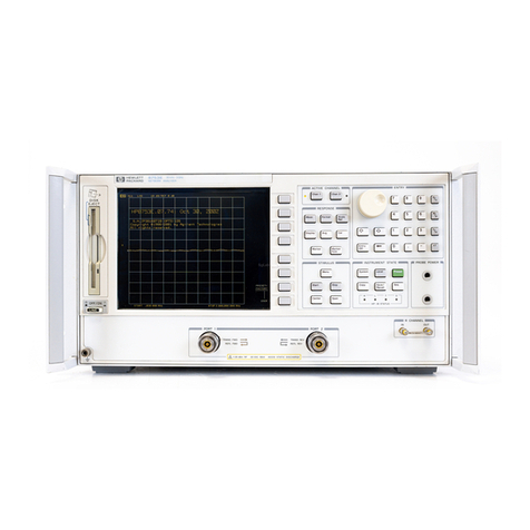
HP HP 8712ET Installation and operation manual

HP Part Number 08714-90054
Printed in USA November 1999
HP 8712ET/ES and HP 8714ET/ES
Installation Instructions for the CPU Board:
HP Part Number 08714-60175 (new) and
HP Part Number 08714-69175 (rebuilt-exchange)
Installation Note

Notice.
The information contained in this document is subject to change without notice.
Hewlett-Packard makes no warranty of any kind with regard to this material, including but not limited to,
the implied warranties of merchantability and fitness for a particular purpose. Hewlett-Packard shall not
be liable for errors contained herein or for incidental or consequential damages in connection with the
furnishing, performance, or use of this material.
© Copyright 1999 Hewlett-Packard Company

Installation Note 08714-90054 3
Description
This document details a special procedure for installing the CPU board in the HP 8712ET/ES
and HP 8714ET/ES RF network analyzers. This special procedure is necessary if the existing
CPU BootROM IC is version E.01.00, or HP part number 08714-80012.
Parts List
NOTE The manuals mentioned in this document can be accessed on the internet by
searching for the part number of the manual at the following Web site:
http://www.agilent.com
For example, to access the Service Guide, go to the Web site and search for
“08714-90017”.
Products Affected:......................... HP8712ET/ES and HP 8714ET/ES RF Network
Analyzers
Serial Numbers:........................... All
To Be Performed By: . . . . . . . . . . . . . . . . . . . . . . (X ) HP Service Center
(X ) Customer or Personnel Qualified by HP
(X ) HP Personnel On-site
Estimated Installation Time:................ 30minutes
Quantity Description HP Part Number
1 A2 CPU Board (new)
—or —
A2 CPU Board (rebuilt-exchange)
08714-60175
08714-69175
1 BootROM IC (U335) 08714-80013
1 IC Extraction Tool
(not used in this special procedure) —

4 Installation Note 08714-90054
Installation Procedure
1. If your CPU board is nonoperable so that you cannot access instrument information by
pressing , go to Step 6. Otherwise,
continue with the following steps.
2. With the existing CPU board still installed, turn on the analyzer and store the correction
constants to a floppy disk. For instructions, refer to Chapter 8 of the analyzer’s Service
Guide.
3. Press . Locate the BootROM version in
the instrument information table on the analyzer’s display.
•If the BootROM version is E.01.01, disregard the remainder of this document and discard
the BootROM shipped with the replacement CPU board. Follow the replacement
instructions for the CPU board in Chapter 3 of the analyzer’s Service Guide (HP part
number 08714-90017).
•If the BootROM version is E.01.00, continue with the following steps.
4. From the instrument information table on the analyzer’s display, record the analyzer’s
serial number and note if Option 100 (SRL and Fault Location) is installed. If Option 100 is
installed, record the keyword from a sticker on the bottom edge of the rear frame, below the
power-cord connector. If the keyword is not available from the sticker, contact your nearest
Hewlett-Packard sales or service office to get a replacement keyword. See the table at the
end of this document for the nearest office.
5. Press . Record the
analyzer’s ethernet address. If the ethernet address is not displayed or cannot be accessed,
contact your nearest Hewlett-Packard sales or service office to get a replacement address.
Do not copy an ethernet address from another instrument (ethernet addresses are unique
for all network interfaces in the world). See the table at the end of this document for the
nearest Hewlett-Packard sales or service office.
6. Remove the CPU assembly. For instructions, refer to Chapter 3 of the analyzer’s Service
Guide (HP part number 08714-90017). Find the section titled “A2 CPU Board Assembly
Replacement” and follow steps 1–5.
7. For nonoperable CPU boards only:
Locate the BootROM IC (U335) on the existing CPU board.
• If the part number printed on the IC is 08714-80013, disregard the remainder of this
document and discard the BootROM shipped with the replacement CPU board.
Complete the replacement instructions for the CPU board in Chapter 3 of the analyzer’s
Service Guide.
• If the part number printed on the IC is 08714-80012:
✓Find the analyzer’s serial number label located on the instrument’s rear panel. Using
the information printed on the label, record the analyzer’s serial number.
✓Using the information printed on the serial number label, note if Option 100 is
installed. If Option 100 is installed, record the keyword from a sticker on the bottom
edge of the rear frame, below the power-cord connector. If the keyword is not
available from the sticker, contact your nearest Hewlett-Packard sales or service
office to get a replacement keyword. See the table at the end of this document for the
SYSTEM OPTIONS
Service
Instrument Info
SYSTEM OPTIONS
Service
Instrument Info
SYSTEM OPTIONS
LAN
LAN Port Setup
Ethernet Address

Installation Note 08714-90054 5
nearest office.
✓Contact your nearest Hewlett-Packard sales or service office to get a replacement
ethernet address. Do not copy an ethernet address from another instrument (ethernet
addresses are unique for all network interfaces in the world). See the table at the
end of this document for the nearest Hewlett-Packard sales or service office.
✓Continue with the following steps.
8. Locate the new BootROM IC (HP part number 08714-80013) shipped with the replacement
CPU board. Install the BootROM IC in the U335 location on the replacement CPU board.
9. Refer again to the Service Guide section titled “A2 CPU Board Assembly Replacement” in
Chapter 3.Begin with step 7 and complete all instructions, including those in “Installing
the CPU Board Assembly.”
10.Turn on the analyzer and wait for the prompt to load the correction constants from a floppy
disk. If the disk is available, insert it into the analyzer’s disk drive and follow the
remaining analyzer prompts. If the disk is not available, it will be necessary for you to
perform the required adjustments when you’re done with this CPU board installation
procedure. The adjustments are described in Chapter 3, Table 3-1, of the analyzer’s Service
Guide.
11.Press . Verify that the analyzer’s serial
number now is listed as “??????????” due to the new BootROM. If a different serial number
is displayed, contact your nearest Hewlett-Packard sales or service office.
IMPORTANT In the following step, a program is used to install the analyzer’s serial number.
When entering the serial number portion of the program, be sure to use:
• the correct serial number for your analyzer (recorded in Step 4 or
Step 7)
• apostrophes around the serial number
• upper-case letters
• a blank space after SNUM
If you make a mistake, you must contact your nearest Hewlett-Packard sales
or service office to get a special password for reprogramming the serial
number.
12.Using the IBASIC editor, enter the following program to install the analyzer’s serial
number.
10 OUTPUT 800; “DIAG:SNUM ‘US345600123’”
20 END
NOTE For detailed instructions on using the IBASIC editor, see Chapter 5 in the
HP Instrument BASIC User’s Handbook Supplement (HP part number
08714-90019).
13.After the program has been entered, press to execute.
SYSTEM OPTIONS
Service
Instrument Info
Run

6 Installation Note 08714-90054
14.Using the IBASIC editor, enter the following program to clear the analyzer’s ethernet
address. When entering the program, you must match upper/lower-case letters as shown.
10 OUTPUT 800; “SYST:COMM:LAN:EADD ‘SimonSaysBeCareful’”
20 END
15.After the program has been entered, press to execute.
16.Using the IBASIC editor, enter the following program to install the analyzer’s ethernet
address (recorded in Step 5 or Step 7). The actual ethernet address is not case sensitive.
10 OUTPUT 716; “SYST:COMM:LAN:EADD ‘080009FA1234’”
20 END
17.After the program has been entered, press to execute.
18.If Option 100 is to be installed, press
. To enable the option, enter the keyword that was
recorded in Step 4 or Step 7. To enter the keyword, it is fastest and easiest to use a
keyboard connected to the analyzer’s DIN KEYBOARD connector on the analyzer’s rear
panel. If you don’t have a keyboard, you can use the analyzer’s arrow keys or the front
panel knob and the key to select and enter characters from the top of the
analyzer’s display. Press when done.
19.Cycle power on the analyzer, and then press
.Verify the analyzer’s configuration is correct.
IMPORTANT If you were not able load the analyzer’s correction constants as instructed in Step
10, you must now perform the required adjustments that are described in
Chapter 3, Table 3-1, of the analyzer’s Service Guide.
Run
Run
SYSTEM OPTIONS
System Config
Options Setup
Install Options
Select Char
Enter
SYSTEM OPTIONS
Service
Instrument Info

Installation Note 08714-90054 7
Hewlett-Packard Sales and Service Offices
UNITED STATES
Instrument Support Center
Hewlett-Packard Company
(800) 403-0801
EUROPEAN FIELD OPERATIONS
Headquarters
Hewlett-Packard S.A.
150, Route du Nant-d’Avril
1217 Meyrin 2/ Geneva
Switzerland
(41 22) 780.8111
France
Hewlett-Packard France
1 Avenue Du Canada
Zone D’Activite De Courtaboeuf
F-91947 Les Ulis Cedex
France
(33 1) 69 82 60 60
Germany
Hewlett-Packard GmbH
Hewlett-Packard Strasse
61352 Bad Homburg v.d.H
Germany
(49 6172) 16-0
Great Britain
Hewlett-Packard Ltd.
Eskdale Road, Winnersh
Triangle Wokingham,
Berkshire RG41 5DZ England
(44 118) 9696622
INTERCON FIELD OPERATIONS
Headquarters
Hewlett-Packard Company
3495 Deer Creek Rd.
Palo Alto, CA 94304-1316
USA
(415) 857-5027
Japan
Hewlett-Packard Japan, Ltd.
Measurement Assistance
Center
9-1, Takakura-Cho,
Hachioji-Shi,
Tokyo 192-8510, Japan
TEL (81) -426-56-7832
FAX (81) -426-56-7840
Australia
Hewlett-Packard Australia Ltd.
31-41 Joseph Street
Blackburn, Victoria 3130
(61 3) 895-2895
Singapore
Hewlett-Packard Singapore (Pte.)
Ltd.
150 Beach Road
#29-00 Gateway West
Singapore 0718
(65) 291-9088
Canada
Hewlett-Packard (Canada) Ltd.
17500 South Service Road
Trans-Canada Highway
Kirkland, Quebec H9J 2X8
Canada
(514) 697-4232
Taiwan
Hewlett-Packard Taiwan
8th Floor, H-P Building
337 Fu Hsing North Road
Taipei, Taiwan
(886 2) 712-0404
China
China Hewlett-Packard Co.
38 Bei San Huan X1 Road
Shuang Yu Shu
Hai Dian District
Beijing, China
(86 1) 256-6888
Other manuals for HP 8712ET
4
This manual suits for next models
3
Table of contents
Other HP Measuring Instrument manuals
Popular Measuring Instrument manuals by other brands

Littelfuse Startco
Littelfuse Startco SE-330 Series manual

Anritsu
Anritsu VectorStar ME7848A Series quick start guide

Emerson
Emerson Rosemount Clarity II T56 quick start guide

Katronic Technologies
Katronic Technologies KATflow 150 operating instructions

Sentek
Sentek LMC-J-0040-1 user manual

Eico
Eico 221 instruction manual