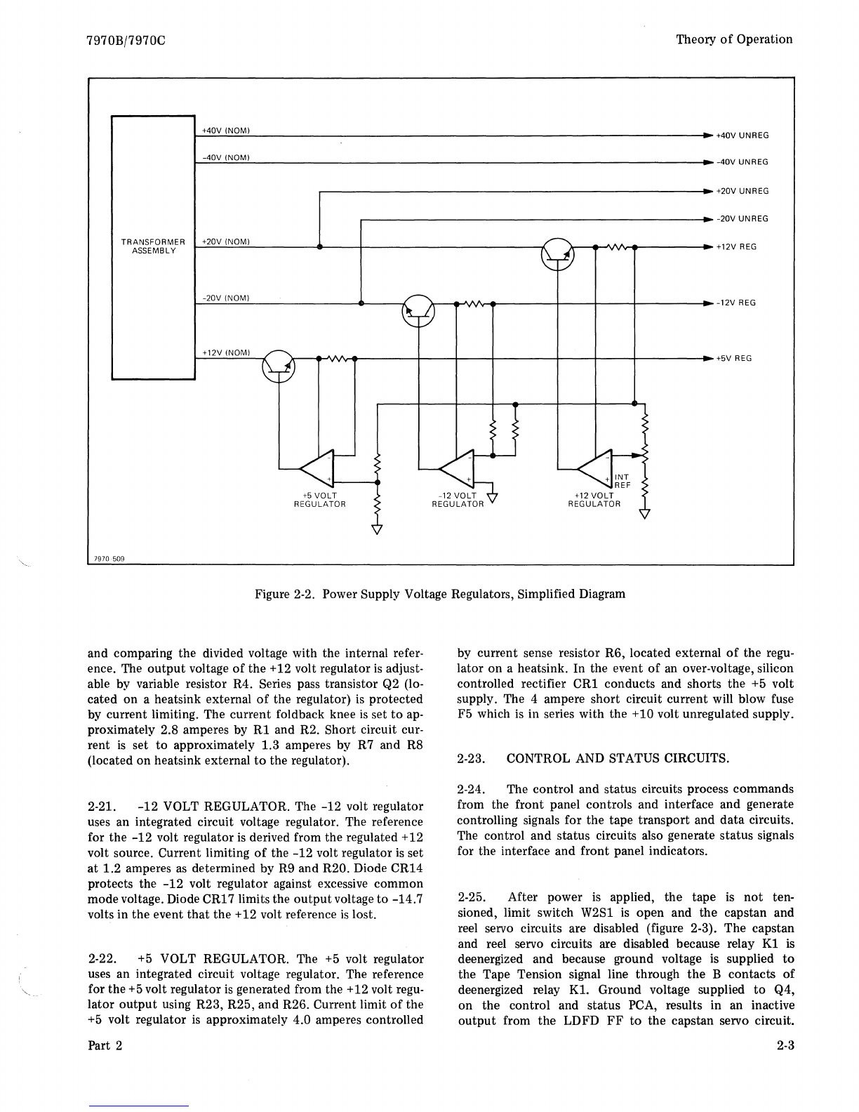
Theory
of
Operation
2-40. The bi-polar ramp generator consists
of
two inte-
grated circuit operational amplifiers (U2 and U3), a symetri-
cal 8-volt clipping network (CR7 through CR11), and a
ramp control network (R42/C28).
2-41. Operational amplifier
U2
initially operates
as
a
saturating
comparator
when a forward
or
reverse command
is
given
or
removed. Near the end
of
a ramp-up
or
ramp-
down
U2
changes from a saturating comparator
to
a linear
amplifier with the non-inverting input
at
O-volts.
2-42. The
output
of
U2
is
held
to
8 volts by a symetrical
clipping network (CR7 through CR11) which establishes
current for the ramp control network. The slope
of
the
ramp
is
determined by the current through R42 (RAMP
control) into integrating capacitor C28. Feedback through
R66 nulls the reference input voltage
to
U2
and the
output
voltage
of
the ramp generator (U3-6)
is
held steady by the
ratio determined by R66 (R35 + R34)
or
R66 (R29 + R28).
2-43. When the Forward or Reverse command
is
removed,
the current through R66 drives operational amplifier
U2
in-
to
saturation and the ramp integrates the 0 volts.
As
the
output
of
the ramp generator (U3-6) approaches 0 volts,
U2
reverts
to
a linear amplifier and the
output
of
the ramp
generator
is
maintained
at
0 volts.
2-44. A High-Speed Forward command (HSFWD) from
the control and status circuits or placing the +
160 service
switch in the on position (up) will allow CR12 and CR13
to
conduct
and reverse bias Q8. With Q8 reverse biased, C25
is
charged through R49. The exponential voltage at the base
of
Q9 rises
to
+12 volts
but
is clipped at +6 volts when Q9
saturates. When the HSFWD command
is
removed
or
the
+160 service switch
is
placed in the
off
position (down),
U1B conducts placing U1B-4, CR12, and CR13
at
0 volts.
This allows Q8
to
conduct and C25 discharges through R48.
The threshold caused by the base emitter turn-on voltage
of
Q9
and the diode drop across CR14 results in a delay
of
approximately 100 ms before motion starts
or
stops.
2-45. A High-Speed Reverse command (HSREV)
or
plac-
ing the
-160
service switch
in
the
on
position, (up) will cause
the high-speed reverse ramp circuit
to
function the same
as
the high-speed forward ramp circuit, except
that
voltage
polarities are reversed. Capacitor C26
is
charged through
R56 and discharged through R54 and R55.
2-46. The LOAD command from the control and status
circuits does
not
control a ramp circuit. The load switch
of
the capstan servo
is
a single step input
to
the capstan servo
amplifier resulting in a nominal 20 ips tape motion.
2-47. The
outputs
of
the bi-polar ramp generator, high-
speed forward ramp generator, high-speed reverse ramp gen-
erator and load switch form a summing junction at the input
of
the capstan servo preamplifier (U4). Diodes CR17 and
CR18 provide clipping
to
protect
the amplifier from over-
load. The preamplifier drives the capstan
motor
power am-
plifier (Q1 through Q6). The dc gain
of
the power amplifier
2-8
7970B/7970C
is
10
volts
per
volt determined by RIO and R11. The power
amplifier
is
operated in class B with Q6 providing negative
current for forward motion and
Q5
providing positive cur-
rent
for reverse motion.
2-48. A
notch
filter in the velocity feedback circuit from
the tachometer
is
selected
to
attenuate
the mechanical re-
sponse
of
the motor-tachometer combination. A compensat-
ing network in the current feedback circuit
is
also selected
depending upon synchronous speed
of
the tape unit.
2-49. Transistor switch Q22 senses the presence
of
tape tension. While the tape is tensioned, Q22 is on,
keeping switch Q20 off. However, when tension is lost
Q22 turns off, allowing Q20
to
turn
on
and switch the
input
of
motor
drive amplifiers Q2, Q4, and Q6
to
ground. This disables the capstan servo. The capstan
motor
circuit
is
completed through
the
B contacts
of
relay
K1
on
the reel servo amplifier
PCA
when
K1
is
energized. Relay
K1
is energized when the LOAD push-
button
is pressed. Once energized,
it
remains energized
until tension is removed.
2-50. REEL SERVO CIRCUITS.
2-51. The reel servo circuits consist
of
a tension circuit,
a voltage switching circuit, a delay circuit, voltage/current
feedback switches, tension arm photosense circuits, pream-
plifiers,
motor
power amplifiers, and reel motors. Figure 2-5
is
a block diagram
of
the reel servo circuit.
2-52. At initial power-on, the tension circuit
is
disabled.
The normally closed contacts
of
LOAD
pushbutton
switch
prevent Q13
of
the tension circuit from conducting. Pressing
the LOAD control allows Q13
to
conduct, energizing relay
K1. With
K1
energized, the capstan and reel servo
motor
circuits are completed.
As
tape
is
tensioned and the tension
arms swing away from the limit switches, power through the
limit switches maintain a forward bias
of
Q13. When power
is
removed,
or
tape tension
is
lost, the relay contacts short
across the reel
motor
windings
to
provide dynamic breaking.
2-53. The voltage switching circuit
is
located
on
the
power regulator printed-circuit assembly. During a high-
speed operation forward or reverse, power
to
the
motor
power amplifiers
is
switched from 22.5 volts
to
57.5 volts
(nominal).
2-54. During a high-speed reverse operation (rewind), the
HSREV command from the control and status circuits
is
gated with TENSION. When
both
reel motors approach full
r/min, the
motor
voltage exceeds the break-down voltage
of
CR4. The condition established by the gating
of
HSREV
and Tension allows current through CR4
to
forward bias
Q5. Voltage switch
Q6/Q7
conducts placing +57.5 volts on
the
+20/40
line. Diode CR2
on
the power distribution
printed-circuit assembly
is
back-biased preventing +57.5
volts from entering the +20 volts line.
Part 2