Setup Instructions
Placing components with sharp or pointed feet directly on the HRS Isolation Base
may cause nicks, scratches, or gouges in the surface. Use of a protective barrier
between any metal-like feet or sharp objects will prevent damage to the HRS
Isolation Base surface. Protection from sharp objects is recommended to prevent
scratches and maintain the original beauty of the HRS Isolation Base.
HRS E1X Isolation Bases are produced with different HRS Footer designs to
optimize the performance of specific components. The type of footer the HRS
Isolation Base was originally configured with is identified on the packaging label
on the outside of the box of each base. The footer designation is also identified by
a color-coded dot located on the back edge of the frame. HRS Isolation Bases have
a unique ability to be modified at any time to optimize performance for a different
component or different environment. If you change the feet of the HRS Isolation
Base, we recommend you also change the color-coded dot on the back of the HRS
Isolation Base so it is easy to identify for what performance setting the base is
currently configured.
The HRS G7 Bi-Directional Noise Reduction Footer does not have any load range
limit. You can place any component on an HRS E1X Isolation Base configured
with G7 Feet. An E1X Isolation Base with G7 Feet is not sensitive to component
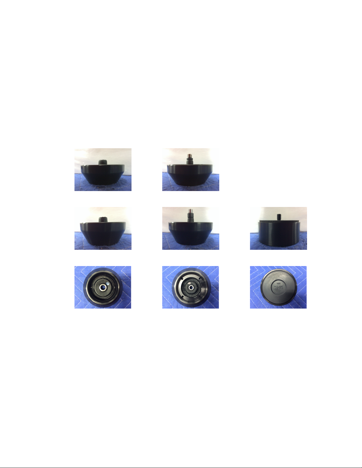
weight or weight distribution. HRS Broadband Isolation Feet (SF2 and SF3) and
HRS Low Frequency Feet (LF2 and LF3) are made in various load ranges to
optimize performance for different component weights. When using the SF and LF
Footers, please verify that the component that will be placed on the HRS Isolation
Base is within the rated load range for SF Footer or is the specific component model
number for LF Footers.
If the SF or LF Footers of the HRS E1X Isolation Base are overloaded, the HRS
isolators will hit a protective stop and significantly reduce the product performance.
If your HRS Isolation Base has SF or LF Feet (pictured on the next page), you can
check to see if the HRS Isolation Base is overloaded by testing for compliance
between the HRS Isolation Base frame and the feet at each corner. With the
component loaded on the HRS Isolation Base, check each corner individually by
pressing down firmly on each corner. An HRS Isolation Base with SF and LF Feet
should be compliant at each corner location and not feel rigid. If there is
displacement at each corner then the HRS Isolation Base is working as designed. If
there is no compliance at one or more corners then the load range should be changed
by HRS to the proper load range. HRS can modify the HRS E1X Isolation Base
load range as many times as needed for a fraction of the original purchase price.
Overloading the HRS Isolation Base for an extended period of time may reduce its
service life and voids the warranty.