HRS TJA Series Instruction Manual

TITLE:
TJA Series Guideline
ETAD-E3232-00
Rev No. 0
HIROSE ELECTRIC CO.,LTD.
OBJECT
PRODUCT:
TJA Series
PAGE: 1OF 25
TABLE OF CONTENTS
Page Number
1. Introduction.................................................................................2
1.1 Guidelines Objectives..................................................................2
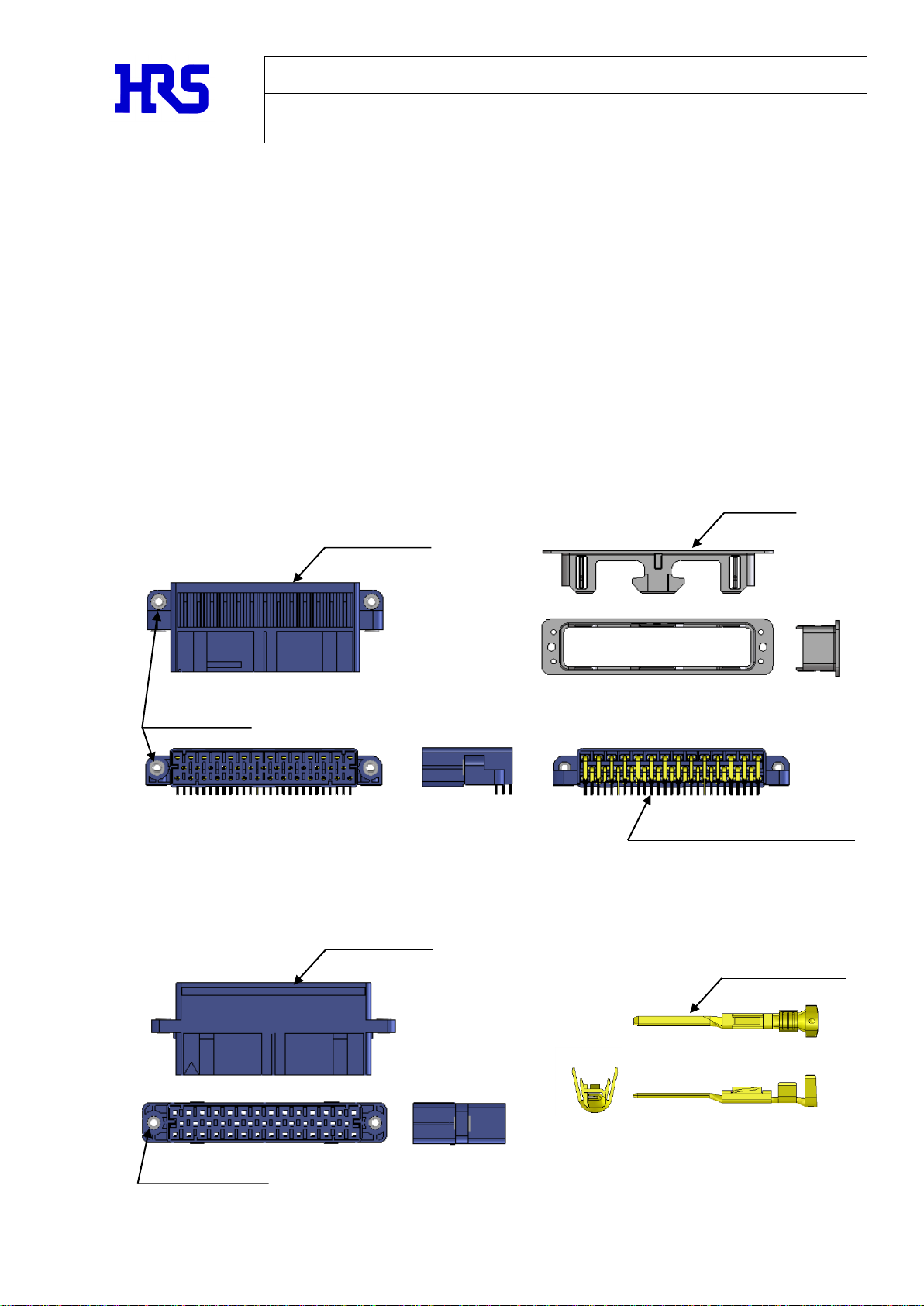
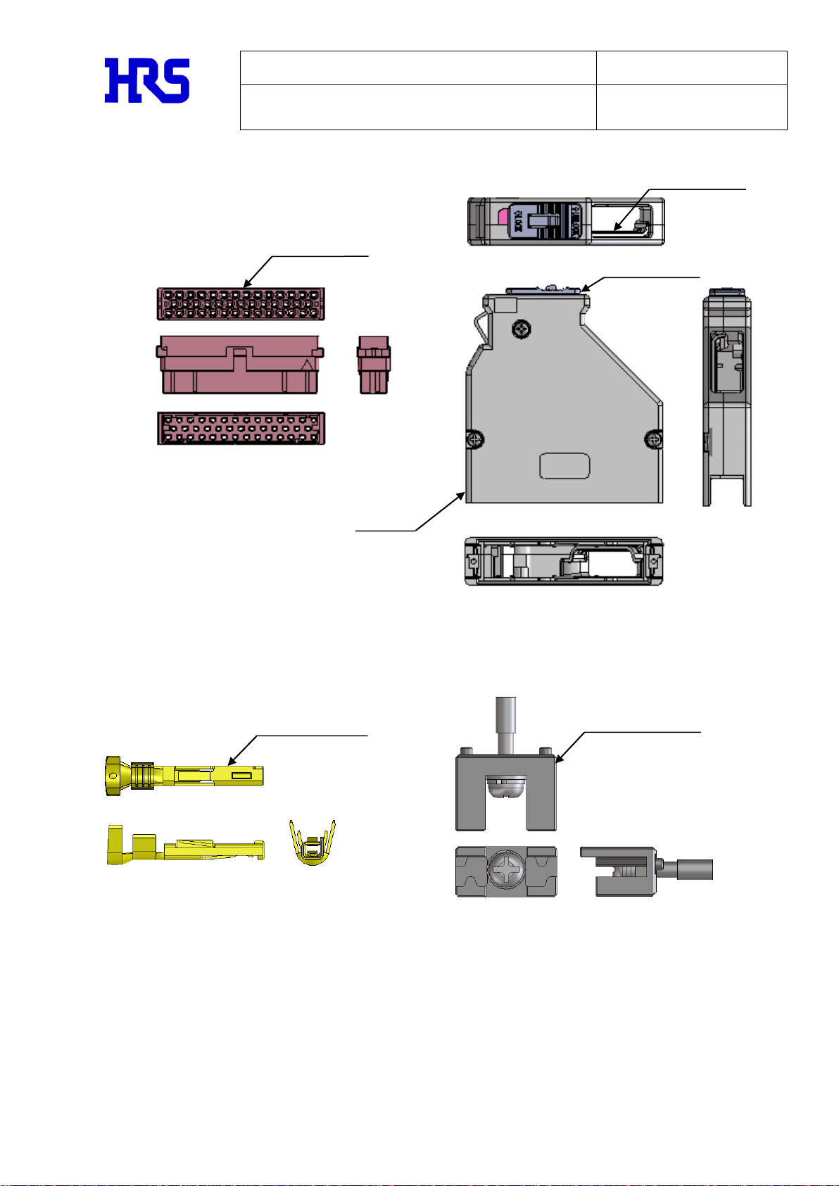
1.2 Names of Connector Components..........................................................2
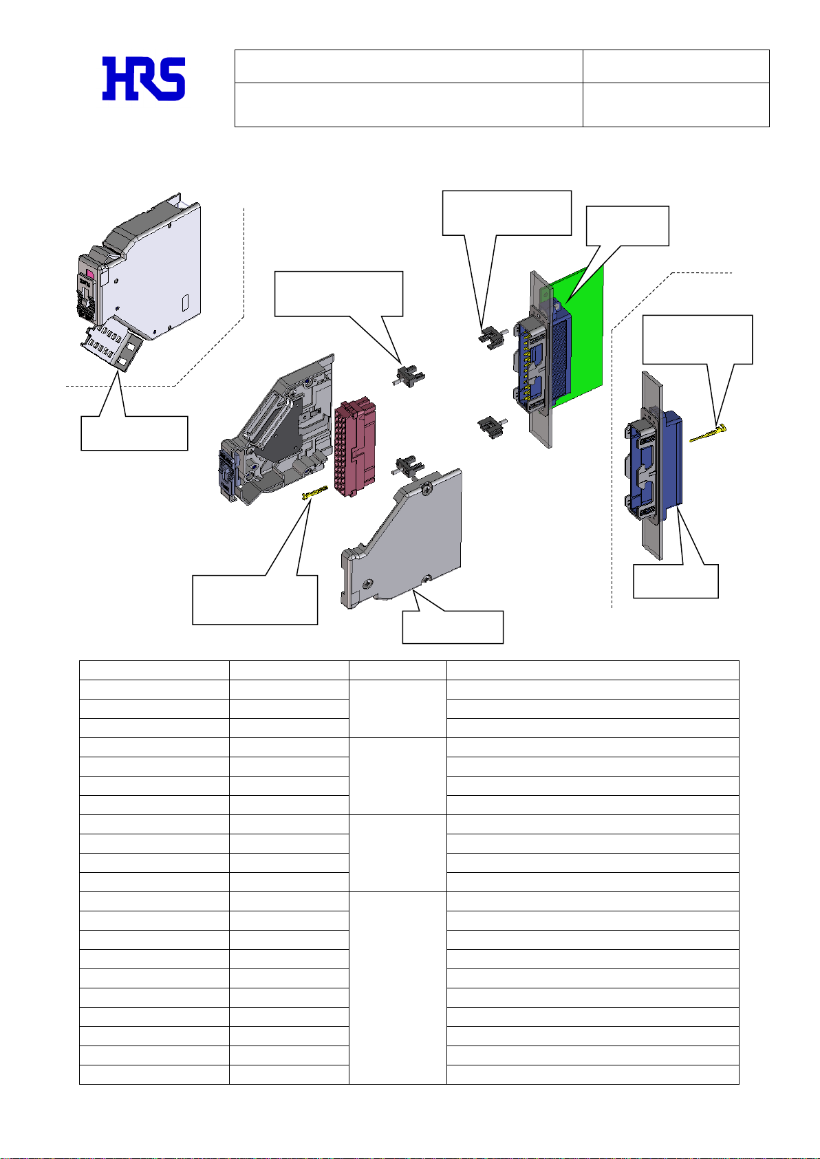
1.3 Product Composition Overview...........................................................4
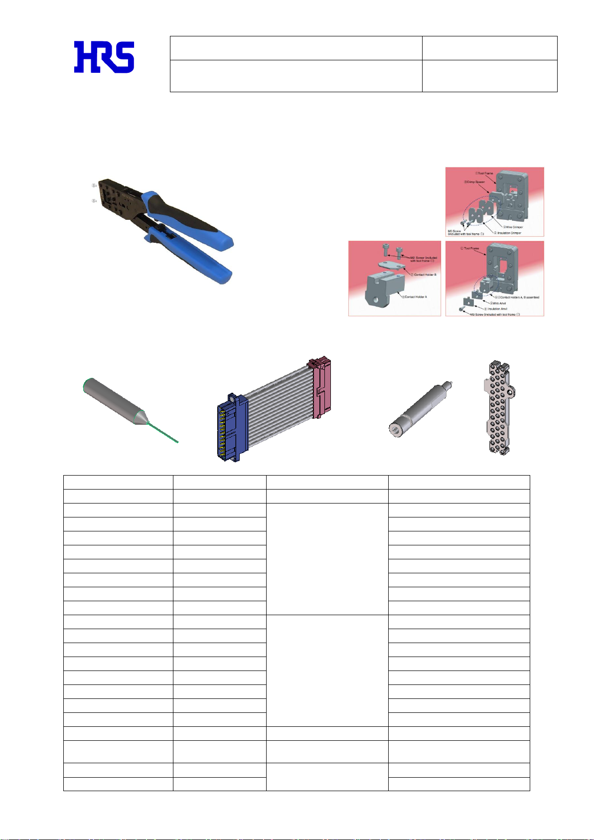
1.4 Tool List..............................................................................5
1.5 Usage Examples.........................................................................6
2. Equipment Design Requirements and Cautions...................................................7
2.1 Receptacle Selection...................................................................7
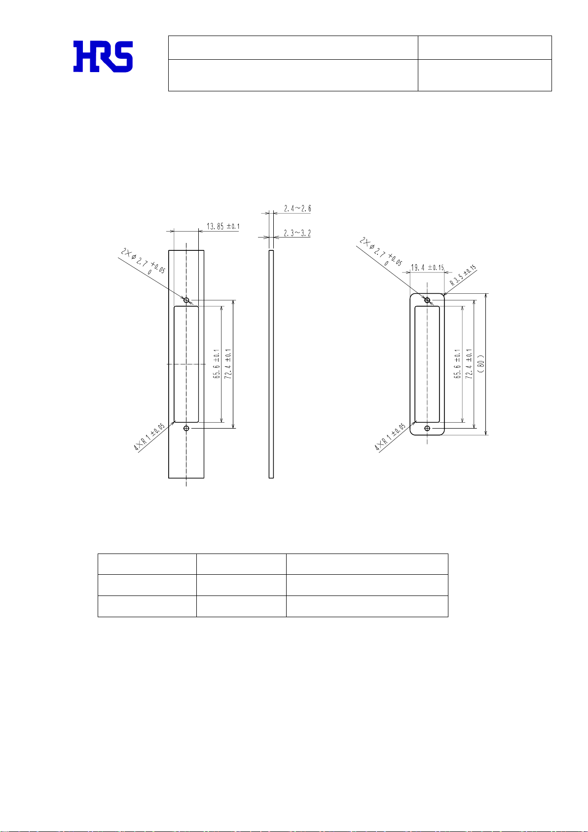
2.2 Panel Cutout ...........................................................................8
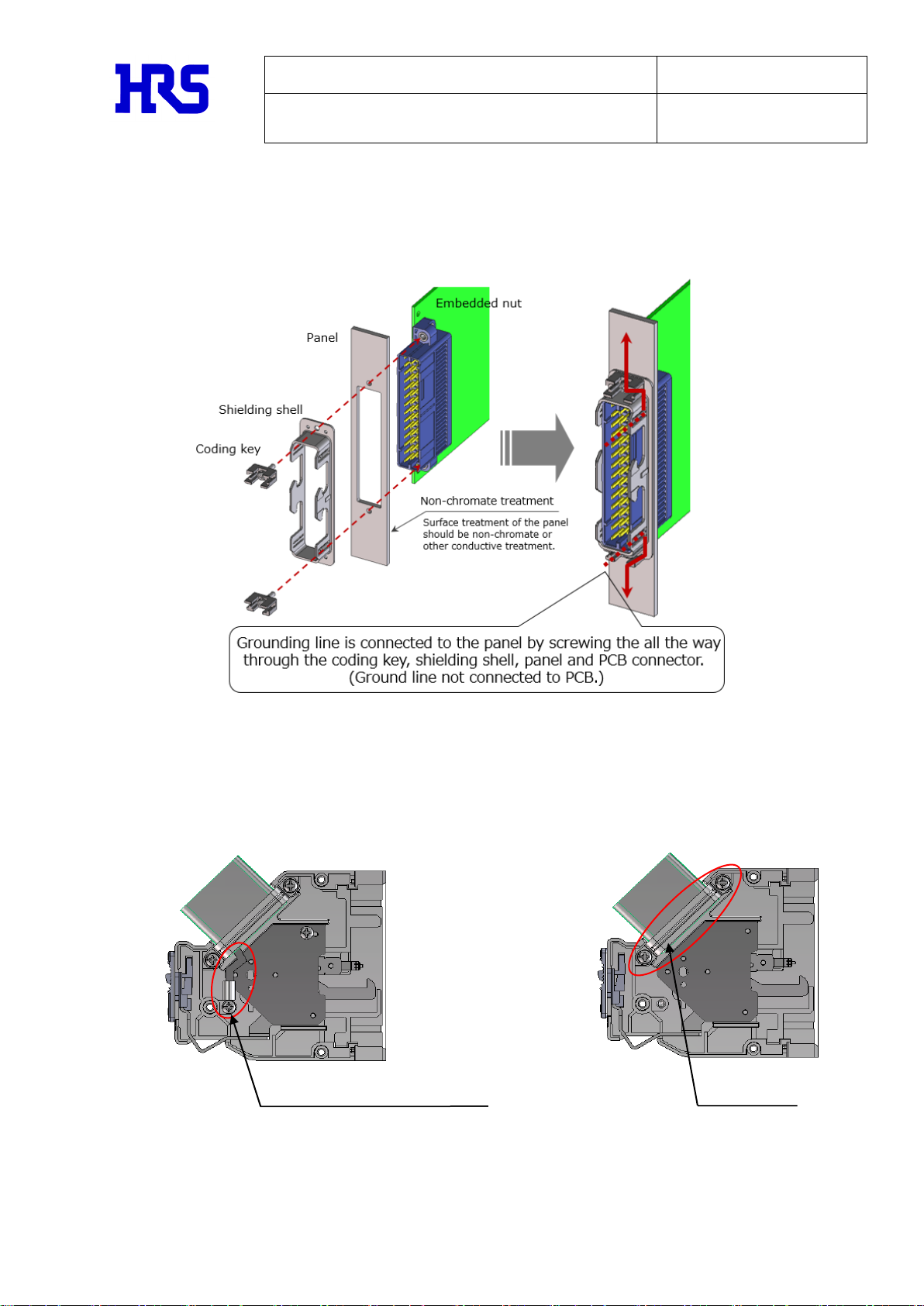
2.3 EMC Prevention .........................................................................9
2.4 Compatible Cables and Crimp contacts ..................................................10
2.5 Plug Selection ........................................................................11
2.6 Misinsertion Prevention Key ...........................................................13
2.7 Temperature Rise Curve ................................................................14
3. Usage Precautions...........................................................................15
3.1 Receptacle Installation Procedure.....................................................15
3.2 Plug Installation Procedure...........................................................17
3.3 Crimp Contact Repair Method...........................................................18
3.4 Cable Clamping Method.................................................................19
3.5 Mating and Locking Method.............................................................20
4. Other Notes .................................................................................21
4.1 Conductivity Confirmation Method ......................................................21
4.2 Contact Assembly Confirmation Method ..................................................22
4.3 Tape for Checking Locking Status ......................................................23
4.4 Connector and Packaging Handling......................................................24
TJA Series Usage Guidelines Revisions Table ................................................. 25
Aug.1.2022Copyright2022HIROSEELECTRICCO.,LTD.AllRightsReserved.

TITLE:
TJA Series Guideline
ETAD-E3232-00
Rev No. 0
HIROSE ELECTRIC CO.,LTD.
OBJECT
PRODUCT:
TJA Series
PAGE: 2OF 25
1.Introduction
1.1 Guideline Objectives
When using the TJA Series manufactured by HIROSE ELECTRIC CO., LTD., please refer to the
guidelines on equipment design and cautions for installation, etc.
Please note that the photos and illustrations shown are representative examples and there might
be differences depending on the product.
The guideline information is subject to change without prior notice.
1.2 Names of Connector Components
Refer to the following figure for the names of the connector parts used in this guideline.
<<Receptacle>>
TJ10A-41P
TJ50A-41P
Shell
Male contact (THR Contact)
P housing
Nut Insert
P housing
Nut Insert
Male Contact
(Crimp Contact)
TJ50A-****PCA
Aug.1.2022Copyright2022HIROSEELECTRICCO.,LTD.AllRightsReserved.

TITLE:
TJA Series Guideline
ETAD-E3232-00
Rev No. 0
HIROSE ELECTRIC CO.,LTD.
OBJECT
PRODUCT:
TJA Series
PAGE: 3OF 25
<<Plug>>
TJ50A-41S-*-CV*
TJ50A-****SCA
S Housing
Unit
Metal Clamp
Slide Button
Female Contact
(Crimp Contact)
TJ-KY-**
Misinsertion
Prevention Key
Aug.1.2022Copyright2022HIROSEELECTRICCO.,LTD.AllRightsReserved.

TITLE:
TJA Series Guideline
ETAD-E3232-00
Rev No. 0
HIROSE ELECTRIC CO.,LTD.
OBJECT
PRODUCT:
TJA Series
PAGE: 4OF 25
1.3 Product Composition Overview
Product Code
Product name
Type
Parts
CL0236-3100-8-00
TJ10A-41P
Receptacle
PCB type 41 pin
CL0236-3118-3-00
TJ10A-28P
PCB type 28 pin
CL0236-3117-0-00
TJ50A-41P
In-line type
CL0236-3101-0-00
TJ50A-41S-U-CV
Plug
Standard clamp metal, upward type
CL0236-3102-3-00
TJ50A-41S-D-CV
Standard clamp metal, downward type
CL0236-3119-6-00
TJ50A-41S-U-CV1
Clamp metal for cable tie fixing, upward type
CL0236-3120-5-00
TJ50A-41S-D-CV1
Clamp metal for cable tie fixing, downward type
CL0236-3103-6-00
TJ50A-1618SCA
Crimp Contact
16 to 18 AWG Female contact for plug
CL0236-3104-9-00
TJ50A-2022SCA
20 to 22 AWG Female contact for plug
CL0236-3105-1-00
TJ50A-1618PCA
16 to 18 AWG Male contact for receptacle
CL0236-3106-4-00
TJ50A-2022PCA
20 to 22 AWG Male contact for receptacle
CL0236-3107-7-00
TJ-KY-PA
Misinsertion
Prevention Key
PA type
CL0236-3108-0-00
TJ-KY-PB
PB type
CL0236-3109-2-00
TJ-KY-PC
PC type
CL0236-3110-1-00
TJ-KY-PD
PD type
CL0236-3111-4-00
TJ-KY-PE
PE type
CL0236-3112-7-00
TJ-KY-SA
SA type
CL0236-3113-0-00
TJ-KY-SB
SB type
CL0236-3114-2-00
TJ-KY-SC
SC type
CL0236-3115-5-00
TJ-KY-SD
SD type
CL0236-3116-8-00
TJ-KY-SE
SE type
Misinsertion
Prevention Key
TJ-KY-P*
Plug
TJ50A-41S-U-CV
Misinsertion
Prevention Key
TJ-KY-S *
Male Contact
(Crimp Contact)
TJ50A-****PCA
Receptacle
TJ10A-**P
Female Contact
(Crimp Contact)
TJ50A-****SCA
Receptacle
TJ50A-41P
Plug
TJ50A-41S-D-CV1
Aug.1.2022Copyright2022HIROSEELECTRICCO.,LTD.AllRightsReserved.

TITLE:
TJA Series Guideline
ETAD-E3232-00
Rev No. 0
HIROSE ELECTRIC CO.,LTD.
OBJECT
PRODUCT:
TJA Series
PAGE: 5OF 25
1.4 Tool Lists
●Hand Tool Frame
【HT 702】
●Contact Extraction Tool ●Harness for Conductivity Confirmation ●Pin-push Inspection Tool
【PQ50S/RE-MD】【TJ50A-41PS-100(30)】【TJ50A/IN-MD】【TJ50A/INCR-MD】
Product Code
Product Name
Type
Parts
CL0250-1001-1-00
HT702
Hand Tool Frame
Frame body
CL0250-1023-4-00
TJ50A-1618-A
Hand Tool Unit
For 16 to 18 AWG
Unit set
CL0250-1023-4-61
TJ50A-1618-A(61)
Insulation crimper
CL0250-1023-4-62
TJ50A-1618-A(62)
Wire crimper
CL0250-1023-4-63
TJ50A-1618-A(63)
Insulation anvil
CL0250-1023-4-64
TJ50A-1618-A(64)
Wire anvil
CL0250-1023-4-65
TJ50A-1618-A(65)
Contact holder A
CL0250-1023-4-66
TJ50A-1618-A(66)
Contact holder B/C
CL0250-1023-4-67
TJ50A-1618-A(67)
Crimp spacer
CL0250-1024-7-00
TJ50A-2022-A
Hand Tool Unit
For 20 to 22 AWG
Unit set
CL0250-1024-7-61
TJ50A-2022-A(61)
Insulation crimper
CL0250-1024-7-62
TJ50A-2022-A(62)
Wire crimper
CL0250-1024-7-63
TJ50A-2022-A(63)
Insulation anvil
CL0250-1024-7-64
TJ50A-2022-A(64)
Wire anvil
CL0250-1024-7-65
TJ50A-2022-A(65)
Contact holder A
CL0250-1024-7-66
TJ50A-2022-A(66)
Contact holder B/C
CL0250-1024-7-67
TJ50A-2022-A(67)
Crimp spacer
CL0902-2202-2-00
PQ50S/RE-MD
Contact Extraction Tool
-
CL0236-3121-8-30
TJ50A-41PS-100(30)
Harness for
Conducitivty Confirmation
-
CL0902-2203-5-00
TJ50A/IN-MD
Pin-push
Inspection Tool
For plug, receptacle inspection
CL0902-2204-8-00
TJ50A/INCR-MD
Plate for receptacle inspection
●Hand Tool Unit
【TJ50A-1618A, TJ50A-2022A】
Aug.1.2022Copyright2022HIROSEELECTRICCO.,LTD.AllRightsReserved.

TITLE:
TJA Series Guideline
ETAD-E3232-00
Rev No. 0
HIROSE ELECTRIC CO.,LTD.
OBJECT
PRODUCT:
TJA Series
PAGE: 6OF 25
1.5 Usage Examples
The TJA Series has a compact design that supports a VME-standard rack and a 3U4HP size panel.
It can be used for inspection equipment and train control devices, etc.
●Railway Ve h i c l e Equipment ●19inch Electronics Rack
Inverter, auxiliary power unit, Inspection equipment, network equipment, etc.
train control device, etc.
Can mount on a
3U4HP size panel.
Aug.1.2022Copyright2022HIROSEELECTRICCO.,LTD.AllRightsReserved.

TITLE:
TJA Series Guideline
ETAD-E3232-00
Rev No. 0
HIROSE ELECTRIC CO.,LTD.
OBJECT
PRODUCT:
TJA Series
PAGE: 7OF 25
2.E q uipm ent Desi gn Requirem ents an d Caut ions
2.1 Receptacle Selection
The receptacle is available in both PCB and in-line types. Please select according to your usage.
<<PCB type>>
After tightening the screws to the board,
do reflow soldering.
Refer to the following for the board pattern.
For dimensions in( ), please apply dimensions of IEC60297-3, DIN41494 and IEEE1101 Euroboard
standards.
The figure shows 41pins pattern below. For 28pins, the portion framed in red(※dimensions)
is not required.
When used as a rated current of 4A, a land width that supports 4A is required.
However, there is a risk that the pattern of the adjacent contacts may interfere with each other.
Please do not place the multi-layer PCB or the contacts for 4A current flow adjacent to each
other.
<<In-line Type>>
The crimp contact connected to the cable can be inserted into the housing.
Crimp Contact
TJ50A-****PCA
Units: mm
unnecessary
for 28 pins
Aug.1.2022Copyright2022HIROSEELECTRICCO.,LTD.AllRightsReserved.

TITLE:
TJA Series Guideline
ETAD-E3232-00
Rev No. 0
HIROSE ELECTRIC CO.,LTD.
OBJECT
PRODUCT:
TJA Series
PAGE: 8OF 25
2.2 Panel Cutout
The panel cutout dimensions for installing the receptacle to the panel are shown below.
(It is sized to fit on the 3U4HP panel of the VME rack)
< Recommended Panel Dimensions > < Recommended Spacer Dimensions >
Note that the panel thickness varies depending on the type.
Type
Product Name
Recommended Panel Thickness (mm) *
PCB type
TJ10A-**P
2.4 to 2.6
In-line type
TJ50A-41P
2.3 to 3.2
*If the panel thickness is less than recommended, adjust the thickness with a spacer.
Please do not use panels thicker that recommended as it will shorted the mating length and
cause contact to become unstable.
Units: mm
PCB type
In-line type
Aug.1.2022Copyright2022HIROSEELECTRICCO.,LTD.AllRightsReserved.

TITLE:
TJA Series Guideline
ETAD-E3232-00
Rev No. 0
HIROSE ELECTRIC CO.,LTD.
OBJECT
PRODUCT:
TJA Series
PAGE: 9OF 25
2.3 EMC Prevention
If EMC/EMI prevention is required, use a conductive treatment such as non-chromate for the
surface treatment of the panel.
For reliable grounding on the plug side, connect the ground wire to the unit with a ring
terminal, or connect the braided shield to the clamp metal.
<Connect the ground wire to the unit with a ring terminal> <Connect braided shield to metal clamp>
If you want to protect loose wires from EMC, use commercial EMC protection materials such as
braided shields or shielding gaskets.
Metal Clamp
Grounding Wires Connection
M3 Screw Size (Commercial)
Aug.1.2022Copyright2022HIROSEELECTRICCO.,LTD.AllRightsReserved.

TITLE:
TJA Series Guideline
ETAD-E3232-00
Rev No. 0
HIROSE ELECTRIC CO.,LTD.
OBJECT
PRODUCT:
TJA Series
PAGE: 10 OF 25
2.4 Compatible Cables and Crimp Contacts
Applicable cables are shown in the table below.
(For the product evaluation of this product, Hitachi Metals cable HF-WV0 with the following
dimensions is used.)
Conductor Size
Cross-Sectional
Area(mm2)
Coating Outer Diameter
(mm)
Crimp Contact
1.25
3.2
TJ50A-1618PCA
TJ50A-1618SCA
0.75
2.8
0.5
2.6
TJ50A-2022PCA
TJ50A-2022SCA
0.3
1.3
<<Crimp Tools>>
If you need a set: Please purchase the frame and unit (die set) according to the compatible
contact.
If you already have a set: Please purchase a unit or a die separately based on the compatible
contact.
Frame
HT702
CL0250-1001-1
This crimp tool is for recommended cables. Please contact us if you wish to use a cable with
dimensions other than what is listed above.
Conductor Size
Cross-
Sectional
Area(mm2)
Coating Outer
Diameter
(mm)
Unit(Die Set)
(WA+IA+WC+IC)
Die Types
Compatible Contact
①WA
②IA
③WC
④IC
1.25
3.2
TJ50A-1618-A
CL0250-1023-4-00
CL0250-
1023-4-64
286651
CL0250-
1023-4-63
286650
CL0250-
1023-4-62
286649
CL0250-
1023-4-61
286648
TJ50A-1618PCA
TJ50A-1618SCA
0.75
2.8
0.5
2.6
TJ50A-2022-A
CL0250-1024-7-00
CL0250-
1024-7-64
286657
CL0250-
1024-7-63
286656
CL0250-
1024-7-62
286655
CL0250-
1024-7-61
286654
TJ50A-2022PCA
TJ50A-2022SCA
0.3
1.3
※The 6-digit number for a single die is the recognition number written on the die.
①Wire anvil (WA)
②Insulation anvil (IA)
③Wire crimper (WC)
④Insulation crimper (IC)
M3 screws
Contact holder
Crimper spacer
M3 screws
Aug.1.2022Copyright2022HIROSEELECTRICCO.,LTD.AllRightsReserved.

TITLE:
TJA Series Guideline
ETAD-E3232-00
Rev No. 0
HIROSE ELECTRIC CO.,LTD.
OBJECT
PRODUCT:
TJA Series
PAGE: 11 OF 25
2.5 Plug Selection
The appropriate plug selection depends on the type of cable to be used and the cabling direction.
Please check the following and select the plug accordingly.
Metal Clamp
Upward Cabling
Downward Cabling
Standard
TJ50A-41S-U-CV
TJ50A-41S-D-CV
Cable Tie
TJ50A-41S-U-CV1
TJ50A-41S-D-CV1
<<Metal Clamp Design>>
CV Clamp metal : Fits inside the unit
CV1 Clamp metal : Protrudes from unit
Using cable ties can reduce cable shaking (see Section 3.4)
Since the unit is exposed to the outside, be careful not to interfere with
other products. The width of the CV is 79.3 mm and the width of CV1 is 93 mm.
When using a cabtire cable, we recommend CV1 which can be fixed at two points.
This is because it is difficult to bend the cable when it is moved, so the cable may rotate
around the center of the clamp if there is only one fixing point and apply a load to the
crimping part.
<<One Fixing Point on CV>> <<Two Fixing Points on CV1>>
Secured at Two Points with
Both Clamp and Cable Tie
Clamp Secures Cable
at One Point
If you move the cable,
the crimping part may move in
the opposite direction.
Even moving the cable,
the crimping part doesn’t move
due to cable tie.
Cabtire Cable
Standard Type
TJ50A-41S-U-CV
4.5
Metal Clamp
Type Secured by Cable Tie
TJ50A-41S-U-CV1
Metal Clamp
2.5
Aug.1.2022Copyright2022HIROSEELECTRICCO.,LTD.AllRightsReserved.

TITLE:
TJA Series Guideline
ETAD-E3232-00
Rev No. 0
HIROSE ELECTRIC CO.,LTD.
OBJECT
PRODUCT:
TJA Series
PAGE: 12 OF 25
In addition, the metal clamp height differs from stated dimensions and the number of cables that
can be stored is different.
Refer to the table below. (It depends on the cable you use, so please check the actual product.)
Type of Clamp
Loose Line (φ3.2)
Cabtire Cable (φ9.6)
CV clamp
41 pins
-
CV1 clamp
31 pins
3
The tensile strength of the cable may be under 98 N depending on the diameter of the cable used,
the material and composition of the sheath, the number of pins, etc.
Therefore, adjust the cable diameter with a shrink tube or copper tape.
Example: When fixing 10 cables with a wire size of 26 AWG and outer diameter of insulator Φ1.3,
put the cable for use, cutting cables and other intervening materials into the shrink tube and
make the overall thickness Φ12.2 to 13.0.
<<Cable Direction>>
Depending on the plug, the cabling direction is either upward or downward.
One plug does not support both directions, so please be careful when choosing the connector.
(The VME standard determines the position of the contact number, so be careful when conforming
to the standard.)
Contact No.1
Contact No.1
Upward Cabling Type
TJ50A-41S-U-CV
Downward Cabling Type
TJ50A-41S-D-CV
Example:Place cable to be used and
cutting cables in a shrink tube.
Aug.1.2022Copyright2022HIROSEELECTRICCO.,LTD.AllRightsReserved.

TITLE:
TJA Series Guideline
ETAD-E3232-00
Rev No. 0
HIROSE ELECTRIC CO.,LTD.
OBJECT
PRODUCT:
TJA Series
PAGE: 13 OF 25
2.6 Misinsertion Prevention Key
The misinsertion prevention key prevents misinsertion even when used multiple adjacent
connectors as shown below.
There are up to 100 different combinations of misinsertion prevention keys.
P and S keys can be attached to both plugs and receptacles.
<<Combination examples>>
When using more than the following combinations, use different parts for the upper and
lower sides.
(Example: Upper side TJ-KY-PA, Lower side TJ-KY-PB, etc.)
・Simultaneous use 5 sets or less ・Simultaneous use 10 sets or less
Prevents possible
misinsertion when connectors
are installed side by side
Interchangeable
Upper side
Lower side
Caution) Each key can be identified by an alphabet engraving.
In addition, the receptacle requires a misinsertion prevention key
to secure the shell.
Lower side
Upper side
Marking positions
組合せ レセ側(上) レセ側(下) プラグ側(上) プラグ側(下)
1
TJ-KY-PA TJ-KY-PA TJ-KY-SA TJ-KY-SA
2
TJ-KY-PB TJ-KY-PB TJ-KY-SB TJ-KY-SB
3
TJ-KY-PC TJ-KY-PC TJ-KY-SC TJ-KY-SC
4
TJ-KY-PD TJ-KY-PD TJ-KY-SD TJ-KY-SD
5
TJ-KY-PE TJ-KY-PE TJ-KY-SE TJ-KY-SE
Combinations
Receptacle (Top)
Receptacle (Bottom)
Plug (Top)
Plug (Bottom)
Lesbian side
(bottom)
組合せ レセ側(上) レセ側(下) プラグ側(上) プラグ側(下)
1
TJ-KY-PA TJ-KY-PA TJ-KY-SA TJ-KY-SA
2
TJ-KY-PB TJ-KY-PB TJ-KY-SB TJ-KY-SB
3
TJ-KY-PC TJ-KY-PC TJ-KY-SC TJ-KY-SC
4
TJ-KY-PD TJ-KY-PD TJ-KY-SD TJ-KY-SD
5
TJ-KY-PE TJ-KY-PE TJ-KY-SE TJ-KY-SE
6
TJ-KY-SA TJ-KY-SA TJ-KY-PA TJ-KY-PA
7
TJ-KY-SB TJ-KY-SB TJ-KY-PB TJ-KY-PB
8
TJ-KY-SC TJ-KY-SC TJ-KY-PC TJ-KY-PC
9
TJ-KY-SD TJ-KY-SD TJ-KY-PD TJ-KY-PD
10
TJ-KY-SE TJ-KY-SE TJ-KY-PE TJ-KY-PE
Receptacle (Top)
Combinations
Receptacle (Bottom)
Plug (Top)
Plug (Bottom)
Aug.1.2022Copyright2022HIROSEELECTRICCO.,LTD.AllRightsReserved.

TITLE:
TJA Series Guideline
ETAD-E3232-00
Rev No. 0
HIROSE ELECTRIC CO.,LTD.
OBJECT
PRODUCT:
TJA Series
PAGE: 14 OF 25
2.7 Temperature Rise Curve
Refer to the following derating curve and temperature rise curve when using with a
current value of 4A or more. Note that the measured values below are the results
when using 18 AWG cable.
Derating Curve
Temperature Rise Curve
TJコネクタ 10芯通電時 軽減曲線(ディレーティングカーブ)
0.00
10.00
20.00
30.00
020 40 60 80 100 120 140
周囲温度[℃]
通電電流[A]
Current [A]
When 10pins are energized
Ambient temperature [°C]
30
20
10
0
0
20
40
60
80
100
120
140
TJコネクタ 1芯通電時 温度上昇曲線
0.00
10.00
20.00
30.00
020 40 60 80 100 120 140
温度上昇[℃]
通電電流[A]
When 1pin is energized
30
Ambient temperature [°C]
20
10
0
0
20
40
60
80
100
120
140
Current [A]
TJコネクタ 1芯通電時 軽減曲線(ディレーティングカーブ)
0.00
10.00
20.00
30.00
020 40 60 80 100 120 140
周囲温度[℃]
通電電流[A]
When 1pin is energized
Ambient temperature [°C]
30
20
10
0
Current [A]
0
20
40
60
80
100
120
140
TJコネクタ 10芯通電時 温度上昇曲線
0.00
10.00
20.00
30.00
020 40 60 80 100 120 140
温度上昇[℃]
通電電流[A]
When 10pins are energized
30
Ambient temperature [°C]
20
10
0
0
20
40
60
80
100
120
140
Current [A]
TJコネクタ 41芯通電時 軽減曲線(ディレーティングカーブ)
0.00
10.00
20.00
30.00
020 40 60 80 100 120 140
周囲温度[℃]
通電電流[A]
When 41pins are energized
30
Ambient temperature [°C]
20
10
0
0
20
40
60
80
100
120
140
Current [A]
TJコネクタ 41芯通電時 温度上昇曲線
0.00
10.00
20.00
30.00
020 40 60 80 100 120 140
温度上昇[℃]
通電電流[A]
When 41pins are energized
30
Ambient temperature [°C]
20
10
0
0
20
40
60
80
100
120
140
Current [A]
Aug.1.2022Copyright2022HIROSEELECTRICCO.,LTD.AllRightsReserved.

TITLE:
TJA Series Guideline
ETAD-E3232-00
Rev No. 0
HIROSE ELECTRIC CO.,LTD.
OBJECT
PRODUCT:
TJA Series
PAGE: 15 OF 25
1. After fixing the connector body to the PCB with M2.5 screws
(commercially available), solder the contacts.
(Recommended tightening torque 0.36 ±0.07 N·m)
2. Insert and screw the panel, shell, and key into the connector body.
(Recommended tightening torque 0.36 ±0.07 N·m)
If the connector is mounted obliquely to the board, screw the panel and board
first.
When there is a gap between the panel and the insert nut, the electrical
continuity cannot be removed.
3. Screw the panel to the PCB.
Please fix it to the PCB using the board mounting bracket (*).
In addition, if the board and the panel are secured first, conductivity
between the connector and the back side of the panel may not be guarenteed.
*Contact the panel manufacturer regarding PCB brackets.
3.Us age Pre c auti o ns
3.1 Receptacle Installation Procedure
<<PCB Type>>
Please prepare commercially
available screws.
Note that the screw head is
located between the adjacent
panel
Please be careful not to interfere.
①Connector Mounting Screws
③Panel Mounting Screws
PCB Bracket
Recommended 2.4 mm or less
(PCB Thickness of 1.6 mm)
< Mounting Adjacent Panels >
Please prepare commercially available
screws. Make sure to select screws
that do not protrude from the panel
so that the screw head does not
interfere with the adjacent panel.
Aug.1.2022Copyright2022HIROSEELECTRICCO.,LTD.AllRightsReserved.

TITLE:
TJA Series Guideline
ETAD-E3232-00
Rev No. 0
HIROSE ELECTRIC CO.,LTD.
OBJECT
PRODUCT:
TJA Series
PAGE: 16 OF 25
<<In-line type>>
1. Insert the crimped male contact in the direction of the arrow until it reaches the inside of
the housing.The contact lance is on the side without the housing polarity mark (Δ).
2. Put the panel, spacer (when panel thickness is insufficient), shell, misinsertion prevention
key into the housing and secure with screws.
(Recommended tightening torque 0.36 ±0.07 N·m)
Since the housing is structured to attach to the panel even when reversed by
180 degrees, install it to the panel in the intended direction, refering to the contact no.
position and the polarity mark.
Panels and spacers are not provided. Please purchase them from panel manufacturers.
Housing
Panel
Spacer
Shell
Misinsertion Prevention Key
Polarity Mark
Contact No.
(If the panel is not thick enough)
Side Without
Polarity Mark
Contact Lance
Side Without Polarity Mark
The lance of the contact is hooked and
secured at the projection of the housing.
Section A-A
Side With Polarity Mark
Aug.1.2022Copyright2022HIROSEELECTRICCO.,LTD.AllRightsReserved.

TITLE:
TJA Series Guideline
ETAD-E3232-00
Rev No. 0
HIROSE ELECTRIC CO.,LTD.
OBJECT
PRODUCT:
TJA Series
PAGE: 17 OF 25
3.2 Plug Installation Procedures
<<Plug>>
1. Insert the crimped female contact in the direction of the arrow until it reaches the inside
of the housing. The contact lance is on the side without the housing polarity mark (Δ).
2. Insert the S housing into Unit A in the direction where the distinction mark is visible.
(It is designed so insertion to the other side is not possible.)
3. Attach the metal clamp to Unit A and tighten the cable. Make sure it is in the right position
with the slide buttons as shown, then cover Unit B from above, and screw it in three places.
(Recommended tightening torque 0.315 ±0.06 N·m)
When using a metal clamp for ground connection, wrap a copper tape around the braid shield
And secure that part with a metal clamp. Depending on the type and number of wires, if the
cmetal clamp and the copper tape do not contact with the product, adjust the thickness with
plastic tape or copper tape.
For ground connection using a commercially available ring terminal, after crimping the ring
terminal, secure it to the ground wire with a M3 screw.
(Recommended tightening torque 0.315 ±0.06 N·m)
4. Insert the key(sold separately) into the plug body
and tighten the screw.
(Recommended tightening torque 0.18 ±0.03 N·m)
Metal Clamp
Screw
fastening
part
Ground Wire
connection part
Slide Button
Unit B
Contact Lance
Side Without Polarity Mark
Distinction Mark
Unit A
Aug.1.2022Copyright2022HIROSEELECTRICCO.,LTD.AllRightsReserved.

TITLE:
TJA Series Guideline
ETAD-E3232-00
Rev No. 0
HIROSE ELECTRIC CO.,LTD.
OBJECT
PRODUCT:
TJA Series
PAGE: 18 OF 25
3.3 Crimp Contact Repair Method
Use the PQ50S/RE-MD tool shown below for contact extraction.
Insert the tool into the area indicated by the white arrow,
and remove it by lowering the contact lance
(In-line type crimp contacts can also be removed in the same way.)
Insert the tool until it reaches the back and gently pull the cable.
If it does not come off even if you pull it lightly, the lance is not released,
so please try again.
If you pull it forcefully, the lance hook part of the housing will be damaged.
Once pulled out, the contact lance lowers, and it may not be hooked even if it is inserted into
the housing.
When reusing, raise the lance to the position shown in the figure below with a pin.
(Lance can only be modified once.)
The housing lance hook where the contact was once pulled out may be chipped off.
If you want to use the contact after inserting it again, please check Section 4.2 "Contact
Assembly Confirmation” and check whether the contact is secured.
In addition, when the contact is removed without using a tool, the lance hook may be shaved down
significantly. Please change the case for a new one.
B
B
Section B-B
Contact
Extraction Tool
Lance Hook
part
Tip Extends Beyond Side Wall
(Standard: half of the plate thickness)
Lance
Aug.1.2022Copyright2022HIROSEELECTRICCO.,LTD.AllRightsReserved.

TITLE:
TJA Series Guideline
ETAD-E3232-00
Rev No. 0
HIROSE ELECTRIC CO.,LTD.
OBJECT
PRODUCT:
TJA Series
PAGE: 19 OF 25
3.4 Cable Clamping Method
To accommodate a variety of cables, a large space for clamping the cables is needed.
Therefore, the cable may not be secured depending on the cable diameter,
sheath material and composition, the number of pins, etc. Adjust the thickness
with a shrink tube or copper tape so that the cable can be secured .
※Recommended cable tensile strength: 98 N
The metal clamp of CV1 can be reinforced with a cable tie as indicated below.
When a load is applied to the cable, optionally fix the cable to the metal clamp with a cable
tie. The cable tie is not provided, so please prepare it.
Depending on the position of the coupling part of the cable tie, it may be difficult to grip
the connector body. In that case, fix it so that the coupling part of the cable tie contacts the
ridged part of the metal clamp.
In addition, please secure the cable to the wall or floor in an environment where vibration is
applied. If the cable is fixed within 25 cm from the cable clamp and there is no slack,
the connector cannot be inserted or removed, so please fix it around 30 cm from the clamp.
Please fix the cable around
30 cm from the cable clamp
Image of cable tie fastening
Image of cable tie size
Cable tie
Cable tie fastening part : Position
Difficult to Grip Connector Body
Cable tie fastening part : Ridged Part Position
Coupling part of the cable
tie on the side of the case
and a finger cannot enter.
Coupling Part of the Cable Tie
Metal Clamp
Ridged part
Aug.1.2022Copyright2022HIROSEELECTRICCO.,LTD.AllRightsReserved.

TITLE:
TJA Series Guideline
ETAD-E3232-00
Rev No. 0
HIROSE ELECTRIC CO.,LTD.
OBJECT
PRODUCT:
TJA Series
PAGE: 20 OF 25
3.5 Mating and Locking Method
When mating the plug with the receptacle, insert the plug straight until it locks.
If you accidentally hit the corner of the plug against the receptacle’s contact,
you may deform the contact.
To prevent accidental mating, there is a slide button for locking the cover case
of the plug. After locking, the unlock button can be fixed by operating the slide button
as shown below.
The locking state can be checked at a glance with the red color under the slide unlock.
(You cannot use the unlock button when the red color is not visible.)
By returning the slide button, the unlock button can be operated.
Slide lock
Slide unlock
Recognize Locking
Status at a Glance
Red →Unlock
Unlock button
Button operable
Button operation disabled
Aug.1.2022Copyright2022HIROSEELECTRICCO.,LTD.AllRightsReserved.
This manual suits for next models
21
Table of contents
Other HRS Industrial Equipment manuals