HRW HPE-BNP1BUS User manual

HRW Limited 504-505, 5/F, Wai Wah Commercial Centre Ph +852 2546 7402
6 Wilmer Street, Sai Ying Pun Fax +852 2546 7403
Hong Kong www.hrw.hk
HPE-BNP1BUS – P1 FLN Gateway to BACnet MS/TP
FW4.01, from Feb. 2012
250 point integration of P1 FLN conforming devices in to BACnet MS/TP networks. Up to 32 P1 devices
may be connected to the gateway for read/write access of up to 250 data-points
Typical Applications
BACnet MS/TP network integration of P1 devices:
System 600, APOGEE Insight
TEC, ATEC, SCU, DPU, DLM
MEC Point Expansion units
HRW HP…P1 devices
Feature Summary
FIND function for initial network device/application identification
Diagnostic function for comms verification and trouble-shooting
Continuous poll for point status changes
User set period for complete point status update
Scaling table for known and customised sensor types

HRW HPE-BNP1BUS V401 Manual 120201.doc E. & O. E. / Subject to change without notice Page 2 of 18
OPERATION OVERVIEW ....................................................................................................................................3
BACNET DEVICE ...................................................................................................................................................3
P1 NETWORK GATEWAY ........................................................................................................................................3
BACNET PRIORITY ARRAY...............................................................................................................................3
TERMINAL MODE ................................................................................................................................................4
HYPERTERMINAL SETTINGS...................................................................................................................................4
Additional Settings............................................................................................................................................5
Connecting at 76800 Baud Rate .......................................................................................................................5
Saving HyperTerminal Settings ........................................................................................................................5
BREAK IN TO TERMINAL MODE..............................................................................................................................5
BACNET CONFIGRATION COMMANDS .........................................................................................................6
P1 CONFIGURATION COMMANDS ..................................................................................................................7
P1 INTEGRATION .................................................................................................................................................8
FIND .......................................................................................................................................................................8
SENSOR TYPE (SCALING)TABLE............................................................................................................................9
Standard Sensor Types ...................................................................................................................................10
POINT TYPE..........................................................................................................................................................10
DATA POINT CONFIGURATION .............................................................................................................................10
DATA BASE MAPPING TOOL...........................................................................................................................12
POINT CONFIGURATION........................................................................................................................................12
SCALING TABLE CONFIGURATION........................................................................................................................13
DOWNLOAD TEXT FILE ........................................................................................................................................14
SCAN P1 FLN NETWORK ..................................................................................................................................14
DIAGNOSTIC DISPLAY......................................................................................................................................14
INSTALLATION & COMMISSIONING ...........................................................................................................15
CONNECTIONS ....................................................................................................................................................16
DIMENSIONS ........................................................................................................................................................16
TECHNICAL DATA .............................................................................................................................................17
ORDERING INFORMATION .............................................................................................................................17
HPE-BNP1BUS...................................................................................................................................................17
ACCESSORIES .......................................................................................................................................................17
OTHER HP_BN SERIES DEVICES..........................................................................................................................17

HRW HPE-BNP1BUS V401 Manual 120201.doc E. & O. E. / Subject to change without notice Page 3 of 18
Operation Overview
The gateway comprises two sections; the BACnet MS/TP device and the P1 network reading data
base.
BACnet Device
The gateway is BTL listed, conforming to the BACnet standard’s requirements for device & object
discovery and network communication initiations and responses.
During commissioning the following should be configured:
Node # (local network unique number)
Device Instance (system-wide unique number)
MS/TP network baud rate
Maximum Master (MM), set to the highest node number existing on the network, for limiting
network traffic to only those devices that exist on the network
250 AV objects relating to the P1 network devices’ data points being read, AV4…AV253
P1 Network Gateway
250 device data points may be configured, from up to 32 P1 devices. Each data point constitutes a
BACnet object (AV).
It is important to have the P1 device manufacturer’s manual available to assist with P1 point address
and type scaling.
Each point of the gateway data base consists of:
1. Device addresses
2. Point numbers within the device addresses
3. Sensor type relating to each point (as defined in the scaling table)
4. A point type; LDI, LDO, LAI, LAO represented as a number, 1…4 respectively
BACnet Priority Array
The BACnet protocol utilises a Priority Array for each object to enable various network devices to take
control of a device’s object based on the level of need. The priorities are in the range 1 (high priority) to
16 (Auto operation).
In respect of this device:
The point database objects are NULL priority, signified by ‘17’ when viewing the points in
engineering Terminal mode
Manually overriding a point value via terminal mode invokes priority level 9
Release of a manual results in an object reverting to NULL or next lowest and still valid priority
level if it has been commanded from another device in the system (such as the BMS)
For normal reading of the P1 network points should always be at NULL priority

HRW HPE-BNP1BUS V401 Manual 120201.doc E. & O. E. / Subject to change without notice Page 4 of 18
Terminal Mode
An HPECOM (serial comm. port) or HPECOMU (USB) data cable is used for terminal mode between
the gateway and a PC running a terminal program. HyperTerminal or Indigo Terminal Emulator from
Shade Blue are recommended. A USB port <> Serial comm port (DB9) converter may be required for
HPECOM if the PC being used does not include a Com 1 serial port.
The following settings reflect HyperTerminal. Please contact us if you require assistance setting up
Indigo.
HyperTerminal Settings
For successful communication between HyperTerminal and the device, initial Properties setup of
HyperTerminal should be as per the screen prints below.
‘Connect to’ Comm Configuration: ‘Settings’ General:
‘Settings’ ASCII Setup:
9600

HRW HPE-BNP1BUS V401 Manual 120201.doc E. & O. E. / Subject to change without notice Page 5 of 18
Additional Settings
Some PC platforms may need keyboard response adjustment for initial Terminal Mode success. These
settings may be done via the PC Control Panel >> Keyboard Settings:
Fastest Repeat rate
Shortest Delay time
Fastest Cursor Blink rate
Connecting at 76800 Baud Rate
Because HyperTerminal does not support 76800 baud then after setting to 76800 the device baud rate
will remain at 9600 baud for HyperTerminal communication and switch to 76800 after Writing the new
baud rate and eXiting terminal mode.
To allow later terminal communication a device set with 76800 baud will operate at 9600 baud for the
first 5 seconds after a power-up. If no attempt to connect the terminal at 9600 baud is made within 5
seconds of a power-up then the device will automatically switch to 76800 for normal network operation.
Saving HyperTerminal Settings
For ease of connection it is recommended to save the HyperTerminal setup for each baud rate you may
wish to use with an easily recognised configuration name. For example:
HPECOM 24 (2400)
HPECOM 48 (4800)
HPECOM 96 (9600)
HPECOM 19.2 (19200)
HPECOM 38.4 (38400)
HPECOM 57.6 (57600)
Break in to Terminal Mode
When HyperTerminal is running and the HPECOM cable is connected to the device the initial terminal
screen will be receiving an ASCII character dump which is the BACnet transmission from the device.
The ASCII dump will appear differently with different device address setting and if HyperTerminal baud
rate is different to the baud rate set in the device. Below is an illustration of how the ASCII dump will
look for a device at default settings; address 98 and 9600 baud.
To break in to terminal mode set Caps Lock on and hold the ‘T’ character key continuously
(TTTTTTT…). After five (5) T’s have been sent to the device it will switch to terminal mode. At this point
the BACnet activity on the network will be halted and the device will display the default user screen.

HRW HPE-BNP1BUS V401 Manual 120201.doc E. & O. E. / Subject to change without notice Page 6 of 18
BACnet Configration Commands
Function Enter Result Options / Comments
Start
communication TTTTT(TTT…) Break in to Terminal mode
With the Caps Lock on, hold the T key down
until the screen updates with HPE data. It is
not necessary to press the enter key to start
communication.
Set node address
(MAC)
1000=1…127
(master)
1000=128…255
(slave)
Network node number is
assigned
Example: 1000=25
1…127 the device will be a ‘token passing
master’
128… 255 the device will become a network
slave after power reset
Set system
Device Instance DI=0…4194303 Unique Device Instance is
assigned
Example: DI=401025 (building 4, network 1,
node 25)
Set BACnet
baud rate 1001=… Network comms speed is
set
2400, 4800, 9600, 19200, 38400, 57600,
76800 Example: 1001=38400
After changing comm. speed it will be
necessary to reconnect with HyperTerminal
at the new comm. speed to save (write) the
change!
Set Maximum
Master address MM=1…127
Highest Master device
address on the network is
registered
Next address searching limited to MM
address
Set Sys. Vendor
ID
(SysVid)
SV=0…255 System vendor specific
features may be available
SV=0 applies generic BACnet operation. If
an entered ID is not implemented then the
generic operation will be applied
Zero the Reset
counters 1=0 All Reset counters are
zeroed
Factory diag. In order as displayed:
Rx timeout, Tx timeout, Hardware reset
Zero the BACnet
comms error
counter
2=0 BACnet comms error
counter is reset Example: 2=0
Zero the M-Bus
comms error
counter
3=0 M-Bus comms error counter
is reset Example: 3=0
Write values as
default W Changes written. Always do this after making changes that
you wish to be permanent
Exit
communication X
Communication with
HyperTerminal no longer
active
Auto X after 240sec without key entry. After
eXit unplug the HPECOM cable to allow
network communication to take place

HRW HPE-BNP1BUS V401 Manual 120201.doc E. & O. E. / Subject to change without notice Page 7 of 18
P1 Configuration Commands
Function Enter Result Options / Comments
Start
communication TTTTT(TTT…) Break in to Terminal mode
With the Caps Lock on, hold the T key down
until the screen updates with HPE data. It is
not necessary to press the enter key to start
communication.
Set P1 FLN
baud rate 1002=… Network comms speed is
set
2400, 4800, 9600, 19200, 38400, 57600,
76800
Example: 1002=9600
Note that P1 devices are typically fixed at
4800 baud
Set Timed Scan
period TS=1…65,000
Force complete all-point
status read every set period
in minutes
Example: TS=10 (default)
(Normal continuous reading still occurs,
reading-in changes only)
Prepare for point
data base text file
download
DE
‘Ready’ will be displayed at
which time the relevant text
file should located and sent
to the gateway
Data base lines may also be manually entered,
one by one
Delete current
point data base
DE followed by
10000=1
Any configuration of
AV4…AV253 is deleted
Download of a text file with new data base will
delete an old existing data base as a matter of
course
Priority Release
all points to NULL R All points are Released to
NULL priority
17 will be displayed at the extreme right of
each data point configuration line to signify
NULL priority
Priority Release
individual point to
NULL
R=4…253 Specified point is Released
to NULL priority
17 will be displayed at the extreme right of the
target data point configuration line to signify
NULL priority
Enable P1 subnet
communication E
Toggles Enabled/Disabled of
M-Bus Subnet
communication
Default Disabled to allow easy configuration
when no M-Bus devices are connected. Always
‘Enable’ when M-Bus devices are connected
and points are configured!
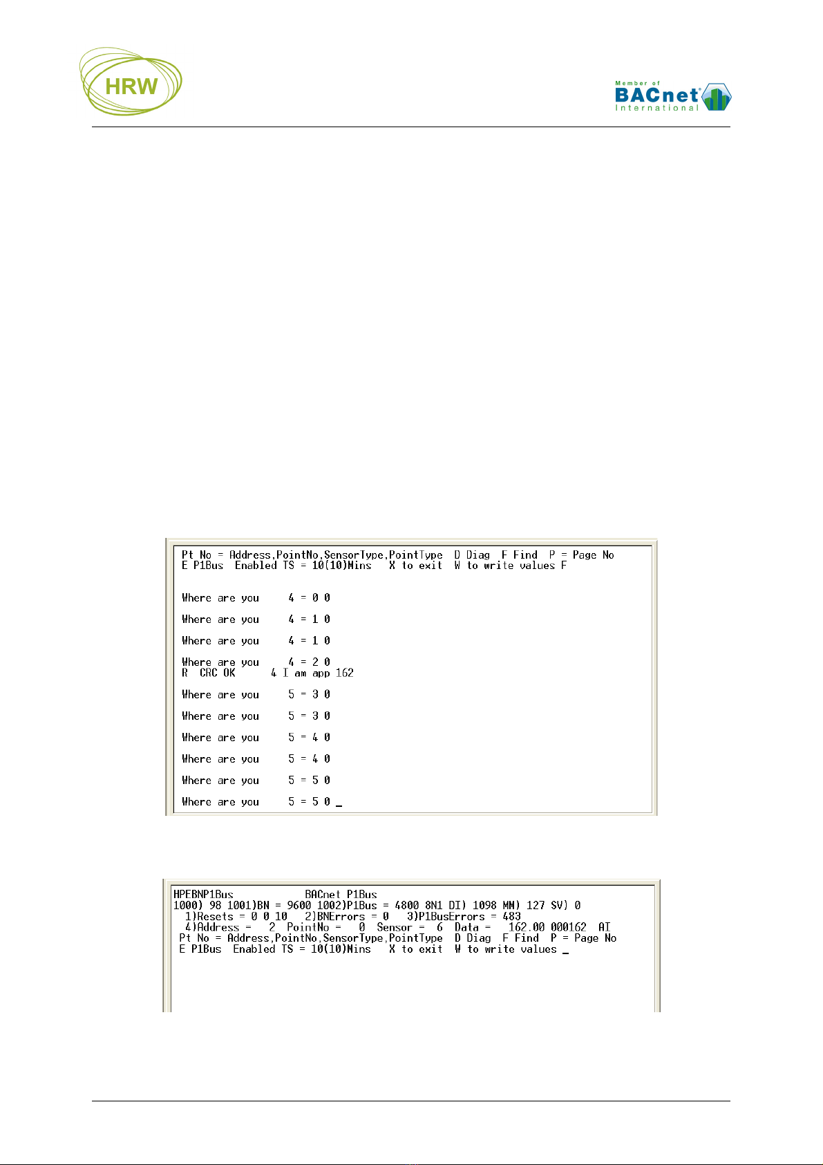
Find F
Identify P1 device addresses
& associated application #
Recommend to take screen print or Capture
Text record as this information is not stored
Scroll page
display P=1…10
Scroll to specific page if
more data-points are present
than can be displayed on
one screen
Example: P=2
The second page of database settings are
displayed
Set point Default
state in event of
network error
DF=0…1
DF=1 last valid read value
will be held after P1
device/point non-responsive
DF=0 value will go to 0/OFF
if P1 device/point non-
responsive for more than
three read attempts
Factory default setting is DF=1
Diagnostic
display D
Point by point response
codes are displayed each
time ENTER is pressed
For data stream analysis between the HPE and
the P1 devices. Create text capture file for easy
analysis of the received data stream
Write values as
default W Changes written. Always do this after making changes that
you wish to be permanent
Exit
communication X
Communication with
HyperTerminal no longer
active
Auto X after 240sec without key entry. After
eXit unplug the HPECOM cable to allow
network communication to take place

HRW HPE-BNP1BUS V401 Manual 120201.doc E. & O. E. / Subject to change without notice Page 8 of 18
P1 Integration
Enter Eto enable the P1 FLN port communication and enter Wto write the enabled state so that it will
still be enabled after any power failure.
Note: To disable the port for any reason, enter E again to toggle from enabled to disabled state.
Find
The gateway Find function enables identification of existing devices on the network, returning their
individual network node addresses and the number of the application running in the device. In
combination with the P1 devices’ application manual, the application number information helps to
decide which points are available in each P1 device, simplifying the creation of the point database of
the gateway.
Enter Fto start the Find function.
The Find function will automatically poll each possible P1 address to find how many devices are on an
existing network. Each address is polled twice in the event a device does not respond on it’s first
polling. Once devices are identified they will be displayed sequentially in the point database list for
cataloguing by the engineer. Each devices’ active Application # is also identified and displayed.
Below we see P1 address 2 has responded and it’s application is #162.
Consequently it is temporarily displayed under the HPE-BNP1BUS point 4 listing, including the
application number.
Any other discovered devices would be listed sequentially, from point 5 onwards as temporary holding
points.

HRW HPE-BNP1BUS V401 Manual 120201.doc E. & O. E. / Subject to change without notice Page 9 of 18
Sensor Type (Scaling) Table
The user configurable Sensor Type table allows up to 16 different sensor scalings to be configured prior
to defining the point data base. The table elements are as follows:
Mult1 (units multiplier)
Mult10 (10’s multiplier)
InputBase (intercept)
By entering Sthe scaling table is revealed. Customisation can be made directly over HyperTerminal or
by download of a configuration file taken from the address calculator tool.
While displaying the table, using a row/column address matrix, each value in the table may be
customized.
For instance, to change Type 1 (row 1) so that it is applicable for °F instead of °C then:
1) Slope of 0.25
a. Units multiplier = 25 therefore enter 13=25 (row#column#=25)
b. Shift decimal place left two places = -2 therefore enter 12=-2
2) Intercept of -48
a. Input Base = Intercept / Slope = -48/.25 = -192 therefore enter 11=-192
Row 0
Row 15
Column 3Column 1

HRW HPE-BNP1BUS V401 Manual 120201.doc E. & O. E. / Subject to change without notice Page 10 of 18
Standard Sensor Types
A number of standard Sensor Types are preconfigured reflecting known TEC and HRW device
input/output parameters.
P1 Sensor types Programming Value Description
Type 0 - HRW 0 HPE/HPC = -10…92°C * (0.1/-10)
Type 1 - TEC 1 Slope 0.14 / intercept -8.889
Type 2 - TEC 2 Slope 0.28 / intercept -3.056
Type 3 - TEC 3 Slope 0.01 / intercept 0
Type 4 - TEC 4 Slope 0.4 / intercept 0
Type 5 - HRW 5 HPE/HPC = -10…92°C * (0.1/-10)
Type 6 - HRW 6 HPE/HPC = Pulse counter (1/0)
Type 7 - HRW 7 HPE/HPC = Digital (1/0)
Type 8 - HRW 8 HPE/HPC = 0…100% (0.1/0)
Type 9 - HRW 9 Seconds (1/0)
Type 10 - HRW 10 Slope 1 / intercept 0
Type 11 - HRW 11 Slope 1 / intercept 0
Type 12 - HRW 12 Slope 1 / intercept 0
Type 13 - HRW 13 Slope 1 / intercept 0
Type 14 - HRW 14 Digital Normally Closed (1/0)
Type 15 - HRW 15 Digital Toggle (1/0)
Point Type
Point Type programming value defines the P1 point in the gateway so that the gateway knows what
BACnet object type should be used when making the point data available on the BACnet MSTP
network.
P1 Point Type Description Gateway Point
Type Gateway Tag BACnet Object
Type
LDI Digital Input 1 DI BV
LDO Digital Output 2 DO BV
LAI Analogue Input 3 AI AV
LAO Analogue Output 4 AO AV
LPACI Pulse Accumulator 3 AI AV
Data Point Configuration
Once it is known which points are required from each device the 250 point data base, points 4…253,
can be created. The elements which make up each point are as follows:
Device address
Point number
Sensor Type, which defines point slope & intercept parameters
Point Type, which defines whether a point is Digital or Analogue, Input or output (BV or AV)
Points are entered in to the HPE-BNP1BUS in the following structure:
<Point #>=<P1 Node #>,<Node Point #>,<P1 Sensor Type>,<Point Type>

HRW HPE-BNP1BUS V401 Manual 120201.doc E. & O. E. / Subject to change without notice Page 11 of 18
In the following HyperTerminal screen print we see four points from an HPE8884P1, device address 2:
Point 1, a digital input (sensor type 7, point type 1)
Point 9, a digital output (sensor type 7, point type 2)
Point 17, an analogue input (sensor type 0, point type 3)
Point 25, an analogue output (sensor type 8, point type 4)
All points are Null priority by default (indicted by value 17 on the right side of the display). To command
from the BACnet BMS then commands must be sent with a priority of 16 or higher
After downloading your point
database and connecting the
network, always remember to
Enable the P1 network comms
and Write the Enabled state so
that comms is automatically
reinstated after a power failure
Normally the gateway will poll the
network for changes only.
The TS (Time Scan) setting will force
a read of all network points every n
minutes regardless of whether point
values have changed since last read
or not.
The value in ( ) is the time pending
until next scan
17
17
17
17

HRW HPE-BNP1BUS V401 Manual 120201.doc E. & O. E. / Subject to change without notice Page 12 of 18
Data Base Mapping Tool
Although all configuration can be typed directly in to the gateway via the terminal program, by email
request or by download from www.hrw.hk, Resources/Tools, you may use our mapping Tool for
creation of a table of data base settings which can be downloaded to the gateway as a text file (*.txt).
Point Configuration
In the example below two P1 devices are configured each with three input points to be read.
Once the information is properly entered in the tool the resultant point configuration data, in the
Download column, may be copied to Notepad for saving as a text file and download to the gateway.
The last row of the download data, 10000=nnn, is a line count for a validity check as part of the
download process. 10000=nnn is not required if manually entering the data configuration lines.

HRW HPE-BNP1BUS V401 Manual 120201.doc E. & O. E. / Subject to change without notice Page 13 of 18
Scaling Table Configuration
By making changes to the Scaling table a Download table is created containing only the changes from
factory default. Below we see the standard setting examples.
By changing Type 1 settings from those for °C to those for °F we see the changes required for
download will appear in the Download column. This download data is then copied to a text file for
download over HyperTerminal using the same process as used for the point database download.
The reference Slope and Intercept values are taken from the P1 device documentation. Entering these
two values automatically calculates the ‘Base’ value required by the HPE-BNP1BUS.
The ‘10’s Multiplier’ and ‘1’s Multiplier’ values must be manually entered in reference to the P1 device’s
documented slope value. In this case, 25 (1’s Multi = 25) with decimal shifted two places to the left (10’s
Multi = -2) = the actual required slope of 0.25 (25*.01=0.25)

HRW HPE-BNP1BUS V401 Manual 120201.doc E. & O. E. / Subject to change without notice Page 14 of 18
Download Text File
While in Terminal mode enter DE. The display will indicate that the existing data base is being blanked
and now ‘Ready’ to receive data base text file:
While in the ‘Ready’ state, navigate to the text file path via the Transfer / Send Text File dialogue:
After download of the text file the display will indicate a check between lines received and lines
expected (indicated by the 10000=nline count generated in the mapping tool configuration table).
If the lines check is correct then the new data base is loaded, otherwise the old data base will be
reinstalled automatically.
Note: To delete all existing point data without downloading a new text file enter DE then enter 10000=1
Scan P1 FLN Network
In terminal mode any scanning of the P1 network will only occur after pressing Enter as a separate
action to any other settings. After exit from terminal mode the scanning will occur automatically.
After pressing Enter, wait for the display to refresh with read values (this may take some time if the
network contains many devices and data points).
Diagnostic Display
For trouble shooting the Diagnostic function allows a clear view of the P1 network data activity.
Enter Dto activate the Diag function. Now, each time you force a scan with Enter you will see the full
request and reply including checksum detail or error messages if applicable.
When a valid node/point change is communicated the point data value(s) will be displayed.
Via the HyperTerminal menus Transfer / Capture text option you can save this communication data for
later analysis; create a capture file, press Enter to force a scan, then stop the capture. Open the
resultant text file with Word to view a formatted record of the communication for analysis.

HRW HPE-BNP1BUS V401 Manual 120201.doc E. & O. E. / Subject to change without notice Page 15 of 18
Installation & Commissioning
This is an RS485 network device designed for mounting in an electrical panel. Ideally it should
be mounted to the panel backplane in a horizontal position (RJ11 sockets on the lower side and
communications ports on the upper side)
Each 24Vac power supply transformer should have the neutral (24Vac N) connection grounded
at the electrical panel earth connection to ensure the device grounding is at the same potential
as the network master’s grounding
Where more than one device is connected to a common transformer ensure that the 24Vac
phasing is the same to each device (‘A’ connects to ‘A’, ‘N’ connects to ‘N’ in all cases)
If the red comms light adjacent to the RS485 terminals emits an obvious flash every time 24Vac
power is applied to the device then the micro-processor may be corrupted. The micro processor
should be replaced
RS485 multi-drop cable should be used for the network connections, complete with end of line
terminating resistors (120Ω). Belden 9841 or equivalent is recommended. The recommended
cable is a low capacitance twisted pair with braid and foil screen
The RS485 cables should be terminated directly at each device in a daisy-chain configuration,
avoiding ‘laterals’ or ‘spurs’
The RS485 screen should be connected at the network master’s ground terminal. The incoming
and outgoing screen at each device should be continuously connected via the S terminal of the
device (note that the device’s S terminal has no electrical connection to the device, it merely
acts as a junction terminal for the purpose of screen continuity)
The RS485 cable should avoid cable routes that run with power cables. Where the RS485
cable must cross power cables then they should cross at 90° avoiding parallel runs beside
power cables
Prior to connection of the slave devices to the RS485 network check that no AC voltage is
present. Double check the network for short circuits between the twisted pair cores and
between the cores and the screen. Ensure continuity of the twisted pair cores and the screen
Check the network master’s +/- terminals for correct voltages to ground (approx. 2.5Vdc) and
connect the RS485 network cable to the network master’s RS485 port
At each device assign an individual address and the baud rate specific to the network. Write the
changes, eXit the terminal application and remove the HPECOM cable
Verify network voltage at the RS485 connector (between +/- and ground) and connect to the
device. Communication can be verified by flashing of the red comms LED adjacent the 3
terminal RS485 connector). Frequency of comms LED flash is baud rate dependant. At higher
baud rates the LED flash may not be obvious, the LED appearing to be continuously on
Where a network runs between buildings and zero earth potential difference between individual
panel 24Vac power supplies cannot be guaranteed, we recommend that a repeater be used to
provide isolation of the sections of the network having differing earth potential

HRW HPE-BNP1BUS V401 Manual 120201.doc E. & O. E. / Subject to change without notice Page 16 of 18
Connections
Dimensions
If using HDA0002 DIN rail adapter brackets the overall depth from the gear plate to the front surface of
the device is 45.5mm
P1
Network
BACnet
RS485
HPE-BNP1BUS

HRW HPE-BNP1BUS V401 Manual 120201.doc E. & O. E. / Subject to change without notice Page 17 of 18
Technical Data
BACnet MS/TP Network Wiring
RS485 Comms Speed
RS485 Network Capacity
P1 FLN Comms Speed
P1 network Capacity
Power Supply
Conformity & approvals
Operating Temperature Range
Storage Temperature Range
Humidity Range
Dimensions
Shielded twisted pair (shield grounded)
Belden 9841 low capacitance twisted pair for RS485 networks
(braided + foil shield, shield continuous throughout the network and
grounded at network origin)
2400, 4800, 9600, 19200, 38400, 57600, 76800 baud
256 nodes over max. 1.2km without repeater
2400, 4800*, 9600, 19200, 38400, 57600, 76800 baud (*typical)
32 devices
24Vac, 50/60 Hz, max. 2.5VA
0…50ºC (32…122ºF)
-5…75ºC (-40…167ºF)
10…95%rH (non-condensing)
126mm (W) x 107mm (H) x 34.5mm (D)
Ordering Information
HPE-BNP1BUS
Description: 250 point gateway – BACnet MS/TP integration of P1 FLN devices - for control
panel mounting
Standard package: 40 units per carton
Accessories
HDA0002 DIN rail adapter brackets, factory fitted
HPECOM Configuration cable (DB9 <> RJ11)
HPECOMU Configuration cable (USB <> RJ11)
U232-P9 RS232 (DB9) <> USB adapter cable
Other HP_BN Series Devices
HPC0662BN Universal Controller, 12 Point, BACnet MS/TP, 24Vac
HPC8884BN Universal Controller, 28 Point, BACnet MS/TP, 24Vac
HPD0440BNMR Network HMI / Universal Ctrl / Scheduler / Modbus RTU gateway
8 Point, BACnet MS/TP, 24Vac
HPD0460BN Network HMI, 12 Point, BACnet MS/TP, 24Vac
HPD0460BNC Network HMI / Universal Controller, 10 Point, BACnet MS/TP, 24Vac
HPD0460BNCT Network HMI / Universal Ctrl / Scheduler, 10 Point, BACnet MS/TP, 24Vac
HPD0460BNT Network HMI / Scheduler, 10 Point, BACnet MS/TP, 24Vac
HPE8884BN I/O expansion, 28 Point, BACnet MS/TP, 24Vac
HPV0662BN VAV / Universal Controller, 13 Point, BACnet MS/TP, 24Vac
HPE-BNMBUS BACnet gateway for M-Bus devices (EN1434), 250 point, 24Vac
HPE-BNMOD BACnet gateway for Modbus devices, 250 point, 24Vac

HRW HPE-BNP1BUS V401 Manual 120201.doc E. & O. E. / Subject to change without notice Page 18 of 18
Notes:
Table of contents
Other HRW Gateway manuals
Popular Gateway manuals by other brands

AudioCodes
AudioCodes Mediant 500 E-SBC user manual

Dr. Neuhaus
Dr. Neuhaus TAINY IQ-LTE Security instructions

Asus
Asus AAM6KBDBX user manual

Distributel
Distributel SR400ac quick start guide

Huawei
Huawei eSpace EGW1530B quick start

Grandstream Networks
Grandstream Networks GXW450 Series Quick installation guide