HSD ES884 User manual

Instructions for use
HSD
MECHATRONIC
DIVISION
5801H0056
EN Rev.02
5801H0056 Rev.02 __________________________________________________________ 1/181
ES884 – ES888
ES915
ES919 – ES929 – ES939
ES983 – ES988

HSD
5801H0056 ________________________________________________________________ 2/181
Information about the document
ISSUED BY CODE REVISION APPROVAL
HSD S.p.A.
Via della Meccanica 16
Loc. Chiusa di Ginestreto
61100 PESARO (ITALIA)
5801H0056 02 UTE 002 / 07
List of updates
Revision Modified paragraph Description of the modification
00 (12.02.2007) First issue First issue
01 (06.03.2007)
§12.7
§12.7.2
Elimination of the note “respect the number of rotations ...”; elimination of the phrase “on the basis of the type and
quality ...” (both the eliminated parts are already present in paragraph §12.7.1).
Additional explanation of the simplified calculation for the centre of gravity.
02 (02.06.2008)
General
§ 5.2
§ 6.2
§ 6.4
§ 9
§ 10.3
§ 10.4
§ 10.6
§ 10.8.5
§ 13.2.2
§ 13.2.2.9
§ 15
Added ES884, ES888, ES915, ES919, ES939, ES983, ES988 models
Symbols updated
Wording on shaft kits corrected
Glossary: generalised wording “ISO” and “HSK”
Motor identification plates and equivalent electrical networks of all motors added
Fixing specifications added
Pressurisation values added
Electrical connections of encoder models and with military connectors added
Note on possible tie-rod breakage added
Sensor connections and positions updated
Sensor adjustment procedure for HSK E63 models added
List of spare parts and note on shaft kit updated
This manual has been drawn up by the Electrospindles Technical Office of HSD S.p.A. and is to be
used by all installers, users and maintenance engineers working with the electrospindle.
This manual is supplied together with the product; it is the most updated documentation available
at the revision date.
For the updates, visit the website www.HSD.it or contact HSD Customer Service.
The manual must be kept in a suitable place that is easily accessed and known to the personnel
using the product. In addition, it must be kept carefully for the entire lifespan of the product, and
must accompany the product if this is ceded to third parties.
This publication is the English translation of the original Italian version of the manual HSD.
In case of discrepancies between this translation and the original version, refer to the original
version in Italian.

HSD
5801H0056 ________________________________________________________________ 3/181
TABLE OF CONTENTS
1PRELIMINARY INFORMATION ....................................................................................6
1.1 DOCUMENTS SUPPLIED WITH THE ELECTROSPINDLE ............................................. 6
1.2 PURPOSE OF THE MANUAL .......................................................................................... 6
1.3 GENERAL SAFETY SYMBOLS ....................................................................................... 6
1.4 RISKS ASSOCIATED WITH THE USE OF THE ELECTROSPINDLE.............................. 7
1.5 RISKS ASSOCIATED WITH INCORRECT USE AND/OR OPERATION.......................... 7
1.6 SPECIFIC RISKS DURING ELECTROSPINDLE MAINTENANCE................................... 8
1.7 RESIDUAL RISKS............................................................................................................ 8
1.8 PURPOSE OF THE PRODUCT ........................................................................................ 8
1.9 RANGE OF APPLICATIONS............................................................................................ 8
1.10 IDENTIFICATION OF THE PRODUCT AND THE MANUFACTURER.............................. 8
1.11 GLOSSARY...................................................................................................................... 9
1.12 GUARANTEE CONDITIONS .......................................................................................... 10
2TECHNICAL SPECIFICATIONS..................................................................................11
2.1 MAIN PARTS OF ES915/ES919/ES929/ES988.............................................................. 11
2.2 MAIN PARTS OF MODELS ES884 - ES888................................................................... 12
2.3 MAIN PARTS OF MODEL ES939................................................................................... 13
2.4 VARIATIONS WITH VERTICAL MOUNTING PLATE..................................................... 14
2.5 VARIATIONS WITH MILITARY CONNECTORS ............................................................ 15
2.6 TECHNICAL CARDS ES884 .......................................................................................... 16
2.7 TECHNICAL CARDS ES888 .......................................................................................... 18
2.8 TECHNICAL CARDS ES915 .......................................................................................... 20
2.9 TECHNICAL CARDS ES919 .......................................................................................... 26
2.10 TECHNICAL CARDS ES929 .......................................................................................... 40
2.11 TECHNICAL CARDS ES939 .......................................................................................... 44
2.12 TECHNICAL CARDS ES983 .......................................................................................... 52
3TRANSPORT, PACKAGING, UNPACKING, STORAGE ............................................65
3.1 WARNINGS .................................................................................................................... 65
3.2 DIMENSIONS AND WEIGHTS ....................................................................................... 65
3.3 TRANSPORT AND PACKAGING CONDITIONS ........................................................... 65
3.4 UNPACKING PROCEDURE........................................................................................... 65
3.5 STORAGE ...................................................................................................................... 66
4INSTALLATION AND INITIAL START-UP..................................................................67
4.1 CHECK ...........................................................................................................................67
4.2 PREPARATION OF THE AUXILIARY SYSTEMS OF THE PLANT................................ 67
4.3 MECHANICAL CONNECTIONS..................................................................................... 67
4.3.1 Positioning of electrospindle (versions with electric fan)............................................. 67
4.3.2 Electrospindle resting surface (versions with rectangular framework) ........................ 68
4.3.3 Fixing structure for spindles with round framework .................................................... 68
4.3.4 Tool change system................................................................................................... 69
4.3.5 Fixing electrospindles with rectangular framework..................................................... 70
4.3.6 Fixing electrospindles with round framework.............................................................. 70
4.3.7 Threaded bores for accessories................................................................................. 70
4.4 PNEUMATIC CONNECTIONS........................................................................................ 71
4.4.1 Air purity .................................................................................................................... 71
4.4.2 Pneumatic connection points for spindles with single-acting cylinder......................... 72
4.4.3 Variation with vertical block (single-acting cylinder) ................................................... 72
4.4.4 Pneumatic connection points ES939 or variations with “T-block” (double-acting
cylinder) ................................................................................................................................. 74
4.4.5 Pneumatic connection points for spindles ES884 - ES888 (single-acting cylinder)..... 76
4.4.6 Internal volumes of the pneumatic cylinders .............................................................. 78
4.4.7 Internal pressurisation ............................................................................................... 78

HSD
5801H0056 ________________________________________________________________ 4/181
4.4.8 Cleaning the tool-holder cone .................................................................................... 78
4.5 HYDRAULIC CONNECTIONS AND SPECIFICATIONS OF THE COOLER................... 79
4.5.1 Specifications for the cooler....................................................................................... 79
4.6 ELECTRICAL CONNECTIONS ...................................................................................... 80
4.6.1 Connectors ................................................................................................................ 80
4.6.2 Military connectors..................................................................................................... 83
4.6.3 Configurable power supply terminal board 220/380 V (optional) ................................ 84
4.6.4 ES988 with configurable terminal board 220/440 V (optional).................................... 85
4.7 BUTTON FOR MANUAL COMMAND OF TOOL RELEASE .......................................... 86
4.7.1 Electrical layout for tool-holder manual release circuit ............................................... 86
5GENERAL CHECKS AFTER INSTALLATION............................................................87
5.1 CHECKS BEFORE THE START-UP .............................................................................. 87
5.1.1 Positioning................................................................................................................. 87
5.1.2 Pneumatic connections.............................................................................................. 87
5.1.3 Electrical connections ................................................................................................ 87
5.1.4 Programming the inverter .......................................................................................... 87
5.2 START-UP CHECKS ...................................................................................................... 87
6USE AND ADJUSTMENT............................................................................................88
6.1 ENVIRONMENTAL CONDITIONS.................................................................................. 88
6.2 RUNNING-IN................................................................................................................... 88
6.3 PREHEATING................................................................................................................. 88
6.4 ELECTRIC FAN.............................................................................................................. 88
6.4.1 Technical characteristics of the electric fan................................................................ 89
6.5 TOOL-HOLDER LOCKING AND EXPULSION DEVICE................................................. 89
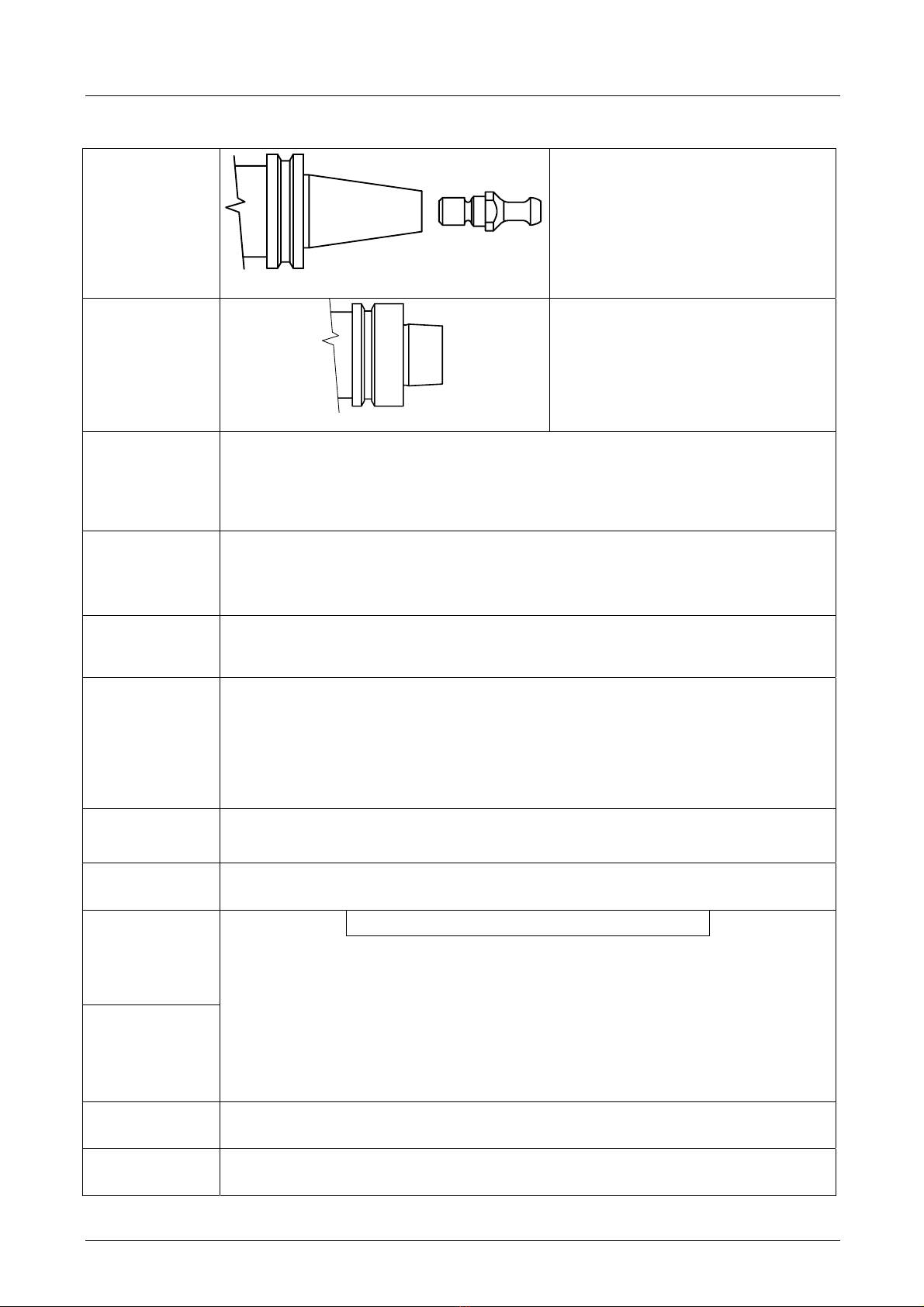
6.6 TOOL-HOLDER CONE................................................................................................... 89
6.6.1 Installation of the tie-rod HSD 0804H0009 in the cone ISO30 DIN69871................... 90
6.6.2 General recommendations for the tool-holder cones.................................................. 90
6.7 TOOL.............................................................................................................................. 90
6.7.1 Speed limits ............................................................................................................... 91
6.7.2 Maximum speed and shape of the tool ...................................................................... 91
6.8 WHAT TO DO IF THE TOOL IS BLOCKED ON THE PIECE BEING WORKED .......... 111
6.9 SENSORS .................................................................................................................... 113
6.9.1 Technical characteristics of the inductive sensors ................................................... 113
6.9.2 Status modes of the electrospindle and corresponding outputs ............................... 114
6.9.3 Output of sensor S3: “shaft idle” signal .................................................................... 114
6.9.4 Use and technical characteristics of the thermal alarm ............................................ 115
6.10 ENCODER (OPTIONAL)............................................................................................... 115
6.10.1 General description.................................................................................................. 115
6.10.2 Technical characteristics of the HSD Square Wave encoder ................................... 116
6.10.3 Output of the HSD Square Wave encoder ............................................................... 116
6.10.4 Technical characteristics of the Lenord+Bauer Square Wave encoder .................... 117
6.10.5 Output of the Lenord+Bauer Square Wave encoder ................................................ 117
6.10.6 Technical characteristics of the Lenord+Bauer sinusoidal encoder.......................... 118
7MAINTENANCE .........................................................................................................124
7.1 SCHEDULED MAINTENANCE..................................................................................... 125
7.1.1 Checking the cleaning of the tool-holder cone and the conical housing in the spindle
shaft 125
7.1.2 Purging the filters of the pneumatic circuit ............................................................... 126
7.1.3 Protecting the conical seat in the spindle shaft ........................................................ 127
7.1.4 Cleaning the tool-holder cone .................................................................................. 127
7.1.5 Lubricating the HSK collet........................................................................................ 127
7.1.6 Checking the connections........................................................................................ 128
7.1.7 Replacing the filters of the pneumatic circuit ............................................................ 128
7.1.8 Bearings .................................................................................................................. 128

HSD
5801H0056 ________________________________________________________________ 5/181
8REPLACING COMPONENTS....................................................................................129
8.1 REPLACING THE ELECTRIC FAN .............................................................................. 129
8.2 REPLACING THE SHAFT KIT FOR MODELS ES884, ES888..................................... 129
8.2.1 Disassembly procedure ........................................................................................... 129
8.2.2 Assembly procedure ................................................................................................ 131
8.3 REPLACING THE SHAFT KIT FOR MODELS ES915,ES919,ES929,ES988............... 133
8.3.1 Disassembly procedure ........................................................................................... 133
8.3.2 Assembly procedure ................................................................................................ 138
8.4 REPLACING THE SHAFT KIT FOR MODELS ES919 ENCODER............................... 142
8.4.1 Disassembly procedure ........................................................................................... 142
8.4.2 Assembly procedure ................................................................................................ 145
8.5 REPLACING THE SHAFT KIT FOR MODELS ES939 ................................................. 148
8.6 REPLACING THE SHAFT KIT FOR MODELS ES939 WITH ENCODER..................... 149
8.6.1 Cylinder unit disassembly ........................................................................................ 149
8.6.2 Disassembly of shaft kit and phonic wheel............................................................... 151
8.7 REPLACING THE ENCODER READERS .................................................................... 154
8.7.1 Replacing the HSD optical encoder reader .............................................................. 154
8.8 REPLACING THE SENSORS....................................................................................... 158
8.8.1 Wiring the sensors of ISO30 models with single-acting piston ................................. 158
8.8.2 Wiring the sensors of HSK models with single-acting piston .................................... 158
8.8.3 Wiring the sensors of ISO30 models with double-acting piston................................ 159
8.8.4 Wiring the sensors of HSK models with double-acting piston................................... 159
8.8.5 Wiring the sensors of HSK models with boosted mounting plate.............................. 160
8.8.6 Accessing the sensors............................................................................................. 161
8.8.7 Position of the sensors ............................................................................................ 161
8.8.8 Accessing the ES939 sensors ................................................................................. 162
8.8.9 Position of the ES939 sensors................................................................................. 162
8.8.10 Position of the sensors in models ES884/ES888 ..................................................... 163
8.8.11 Description of the sensor unit .................................................................................. 163
8.8.12 Replacing the sensor unit ........................................................................................ 164
8.8.13 Adjusting sensor S1 (both ISO and HSK versions) .................................................. 165
8.8.14 Adjusting sensor S2 in ISO versions........................................................................ 166
8.8.15 Adjusting sensor S2 in HSK versions....................................................................... 167
8.8.16 Adjusting sensor S3 (both ISO and HSK versions) .................................................. 167
8.8.17 Adjusting sensor S4 (HSK versions only)................................................................. 168
8.8.18 Kit of gauges to adjust sensors S1 and S4 HSK F63 (code HSD 3811H0110)......... 169
8.8.19 Kit of gauges to adjust sensors S1 and S4 HSK E63 (code HSD 3811H0739) ........ 171
9OPTIONAL PARTS....................................................................................................173
9.1 COOLING WITH FORCED AIR .................................................................................... 173
9.2 INSTALLATION OF THE KIT FOR COOLING WITH FORCED AIR ............................ 174
10 TROUBLESHOOTING...............................................................................................175
11 LIST OF SPARE PARTS ...........................................................................................179
12 DISPOSAL .................................................................................................................180
13 CUSTOMER SERVICE ..............................................................................................181

HSD
5801H0056 ________________________________________________________________ 6/181
1PRELIMINARY INFORMATION
1.1 DOCUMENTS SUPPLIED WITH THE ELECTROSPINDLE
The documentation supplied with the product consists of:
•the Manufacturer's Declaration in accordance with Appendix IIB of Directive 2006/42/EC
•the product inspection certificate.
•this manual, containing the warnings and instructions for transport, installation, operation,
maintenance and disposal of the product.
i
Check that all the documents defined above are present at the time of delivery; if
necessary, request a new copy from HSD S.p.A.
1.2 PURPOSE OF THE MANUAL
•The manual is an integral part of the electrospindle and must compulsorily accompany it,
otherwise the electrospindle would be without one of its essential safety requirements.
•The manual must be handled with care, distributed and made available to all persons
concerned.
•The purpose of the warnings is to protect the safety of the persons exposed to residual risks.
•The instructions provide tips on the proper behaviour for the correct use of the product, as
intended by the manufacturer.
•In the event that contradictions are discovered between these instructions and the safety
standards, please contact HSD S.p.A. for any corrections and/or amendments, on +39 0721
439638.
•In order to avoid incorrect operations that could cause danger for people, it is important to read
and understand all the documentation supplied with the electrospindle.
•It is important to keep this manual in a suitable place and always within reach for consultation.
1.3 GENERAL SAFETY SYMBOLS
In this manual, some information of particular interest may be preceded by one of the following
symbols:
Indicates a procedure, practice or any other similar
measure that, if not observed or correctly followed, may
cause personal injuries.
Indicates an operational procedure, practice or any other
similar measure that, if not observed or correctly
followed, can damage or completely destroy the product.
Indicates that the marked part may be red-hot and must
not be touched without due care.
i
Indicates information of particular general interest that
must not be ignored.

HSD
5801H0056 ________________________________________________________________ 7/181
1.4 RISKS ASSOCIATED WITH THE USE OF THE ELECTROSPINDLE
•HSD S.p.A. does not know, and cannot know, the conditions of installation of the
product, so the installer or end user must carry out an analysis of the risks, relating
specifically to the method and typology of installation.
•It is, however, the responsibility of the party conducting the installation to guarantee an
adequate degree of protection against the risk of accidental contact with moving parts and
elements.
•The installer and user must also bear in mind other types of risk, in particular those arising from
the presence of foreign bodies and from the transport of explosive, inflammable or toxic gases at
high temperatures.
•Furthermore, consideration must be given to the risks inherent in the maintenance operations
that must be carried out under conditions of maximum safety by isolating the electrospindle and
with the tool at a standstill.
•The finished machine on which the HSD product is to be integrated will be subject to an overall
risk evaluation, and a conformity declaration must be granted, according to Directive
2006/42/EC, appendix IIA, and successive amendments.
•It is forbidden to put the product into operation before the machine into which it is to be
incorporated complies with the provisions of Directive 2006/42/EC and successive
amendments.
1.5 RISKS ASSOCIATED WITH INCORRECT USE AND/OR OPERATION
•It is absolutely forbidden to disconnect, remove, modify or in any other way deactivate any
safety, protection or monitoring device, both relating to individual devices and to the
electrospindle as a whole.
•Do not place your hands, arms or any other parts of the body in the vicinity of moving parts.
•The use of the electrospindle in atmospheres or environments with the risk of explosion is
forbidden.
•It is forbidden for an unauthorised operator to eliminate possible defects or faults in the
functioning of the electrospindle and/or to change the type of operation and installation.
•After carrying out any special operations involving the removal of guards, barriers or other
protective devices, install these again before restarting the electrospindle and check that they
are correctly positioned and functioning efficiently.
•All the protective and safety devices must be maintained in a perfect and efficient condition at all
times. The plates with indications, recommendations and danger warnings must be kept in place
and fully efficient.
•When looking for the cause of any fault or malfunction of the electrospindle, take all the
precautions described in the manual in order to avoid personal injury or damage to equipment.
•Remember to tighten all screws, bolts or ring nuts of all mechanical control or adjustment
elements.
•Before starting up the electrospindle, ensure that all the safety devices are installed and in
proper functional order; if this is not the case, it is absolutely forbidden to start it up, and the
person responsible for internal safety or the section head must be informed immediately.
•The operator must be equipped with Personal Protective Equipment (PPE) in accordance with
the provisions of the laws in force; wearing loose clothes and various accessories (ties, wide
sleeves, etc.) is forbidden.
•It is absolutely forbidden to use types of tool holder that do not correspond to the models defined
in the manual; this would cause the risk of breakage or imperfect hook-up of the tool holder
cone.

HSD
5801H0056 ________________________________________________________________ 8/181
1.6 SPECIFIC RISKS DURING ELECTROSPINDLE MAINTENANCE
To safely operate an HSD product fitted on the machine, refer to the manual of the
machine itself.
•Disconnect the product from the main power supply before carrying out any maintenance
operations!
•Even when the product is disconnected from the power supply, the rotating parts (and moving
parts in general) can nevertheless move, due to their inertia; before carrying out maintenance
operations therefore, check that the moving parts of the product are at a standstill.
1.7 RESIDUAL RISKS
The product has been analysed on the basis of Directives 2006/95/EC and 2006/42/EC in order to
identify possible sources of risk. The risks that still remain (residual risks) and the respective
countermeasures are described in the relevant sections of this manual.
1.8 PURPOSE OF THE PRODUCT
The product cannot work independently: it is a part of a machine, and is designed to be assembled
with other machine parts, or to be incorporated in a machine, so as to form a machine in
accordance with Directive 2006/42/EC.
It is forbidden to set the product into operation before the machine into which it is to be
incorporated complies with the provisions of Directive 2006/42/EC and subsequent
amendments.
1.9 RANGE OF APPLICATIONS
The product has been designed to carry out milling and boring operations in the field of wood and
its derivatives, plastic, fibre, aluminium, and light machining operations on other metals.
The quick replacement of the shaft unit complete with bearings is possible on some models, using
the “shaft kit”. For further information see section 11 List of spare parts
All the electrospindles have a mechanical reaction system that neutralises the axial force of the
piston on the shaft during the tool changing phase, guaranteeing the integrity of the precision
bearings.
1.10 IDENTIFICATION OF THE PRODUCT AND THE MANUFACTURER
The EC marking plate and the serial number represent the only elements to identify the product
acknowledged by HSD S.p.A. The user of the product is obliged to maintain the integrity of these
signs.
In section 2 you can see the position of the EC mark and the serial number of the product.

HSD
5801H0056 ________________________________________________________________ 9/181
1.11 GLOSSARY
ISO
ISO DIN69871 CONE HSD TIE-ROD
Tool-holder cone hooking system,
described by the standard DIN 69871.
On the electrospindle there is a plate
similar to that alongside, indicating the
type of hook-up (ISO or HSK) and the
type of HSD tie-rod (see paragraph
6.6).
HSK
HSK DIN69893 CONE
Tool-holder cone hooking system,
described by standard DIN 69893.
The electrospindle has a plate similar to
that alongside, indicating the type of
hook-up (ISO or HSK).
Degree or type
of dynamic
balancing
Value of the balancing of a rotating object according to the standard ISO 1940/1,
indicated by the letter G.
Low G values correspond to higher balancings; the maximum balancing precision is
G=0.4.
G takes on discrete values in relation to multiples of 2.5 (G=0.4 G=1 G=2.5 …).
Routine
maintenance
All the activities intended to maintain the operating and functioning conditions of the
electrospindle as provided for by HSD S.p.A. at the moment of its launch on the market;
it is carried out through scheduled operations to adjust, repair and replace parts.
Service S1
Function under constant load, of a duration sufficient to allow the electrospindle to attain
a thermal equilibrium.
The corresponding abbreviation is S1.
Service S6
Sequence of identical operating cycles, each comprising a period of operation under
constant load and a period of operation without load while maintaining the rotational
speed; there is no rest period.
The corresponding abbreviation is S6, followed by the percentage ratio between the
period of operation under load and the length of the cycle.
Example: S6 40%.
(40% period of operation under load, 60% period of operation in rotation without load).
Rated voltage Maximum power supply voltage of the electrospindle.
Rated
frequency Minimum frequency at which rated voltage is supplied.
Torque
Power
..Torque (Nm) = [ 60 · power (W) ] :[ 2 · Π· rpm ]..
Providing a precise physical definition of torque and power would be going beyond the
scope and possibility of this manual. Nevertheless the torque can be roughly
correlated to the force with which the tool contacts the piece being machined (and for
the same torque value, the force increases as the diameter of the tool decreases). The
power, on the other hand, is proportional to the torque and the rotational speed and
determines the maximum machining speed (taking into consideration the performance
of the tool, the characteristics of the material being machined and the type of
machining).
Nominal
characteristics All the various rated values reached in relation to the rated frequency.
Coolant Fluid, liquid or gas (including air) by means of which the heat is transferred from the
spindle to the atmosphere.

HSD
5801H0056 _______________________________________________________________ 10/181
1.12 GUARANTEE CONDITIONS
HSD S.p.A. guarantees that the electrospindle has been inspected at its plant with a positive result.
Works under warranty shall be performed free at the HSD S.p.A. facilities, transport at the
customer's expense; HSD S.p.A. shall not be liable for termination of production during the
warranty period.
The warranty does not cover faults due to normal wear of those parts which, by their nature, are
subject to rapid and continuous wear (e.g. gaskets, belts, bearings, etc.). In particular, HSD S.p.A.
gives no guarantee as to the working life of the bearings, as this depends on various factors
including: the degree of balancing of the tools, the types of machining operation, collisions and/or
mechanical stresses beyond the values indicated by the manufacturer.
HSD S.p.A. accepts no liability for faults in the conformity of the electrospindle caused by a failure
to observe the standards of the instruction manual or the incorrect operation or handling of the
electrospindle. The buyer shall therefore have a right to replacement of parts found to be defective
only if the faults have not been caused by tampering, namely by installing non-original HSD spare
parts and/or replacing components not provided for and not authorised in this manual and, in any
case, without the prior written approval of HSD S.p.A.
On no account shall HSD S.p.A. or its suppliers be responsible for damage (including but not limited
to damage to the physical integrity of the product or damages due to loss or reduced earnings,
stoppages in production, loss of information or other economic losses) resulting from the use of
HSD products, even in cases where HSD S.p.A. has been warned of the possibility of such damage.
The buyer's warranty shall be voided if HSD S.p.A. is not notified in detail, in writing, of the nature
of any faults discovered in the electrospindle within 15 days of the fault being discovered. The
buyer's warranty shall also be voided in the event that he does not allow the seller to carry out any
requested inspections, or if the seller requests the return of the defective parts and the buyer fails
to return them within two weeks of the request.
Measured drawings and photographs are provided purely as reference examples for a simpler
understanding of the text.
In line with its policy of continuous development and advancement of the product, the company
reserves the right to modify both its functional and aesthetic characteristics, to vary the design of
any functional element or accessory, or to suspend production and delivery; this without
undertaking to give notice to anyone and without incurring any other obligation. Furthermore, HSD
S.p.A. reserves the right to make any structural or functional modifications, as well as the
modification of the supplied spare parts and accessories, without the obligation of communicating
these changes to anyone or assuming any other obligation.

HSD
5801H0056 _______________________________________________________________ 11/181
2TECHNICAL SPECIFICATIONS
2.1 MAIN PARTS OF ES915/ES919/ES929/ES988
12 1
8
4
6
7
9
10
9
15
14
13
17
18
3
2
5
16
11
1 Movable electrical connectors 10 Framework
2 Fixed electrical connectors 11 Electric fan (air-cooled versions only)
3 EC marking plate 12 Pneumatic connectors
4 Serial number 13 Cover of the sensor area
5 Connector for sensor on accessories (e.g. C-axis) 14 Button for the manual release of the tool-holder
6 “Nose” 15 Pneumatic cylinder
7 Shaft 16 Resting surface
8 Tool hooking system 17 Seat for centring tang
9 Threaded bores for accessories
(on the sides and the front flange) 18 “T” slot for fixing

HSD
5801H0056 _______________________________________________________________ 12/181
2.2 MAIN PARTS OF MODELS ES884 - ES888
1
2
7
5
12
3
9
10
1
8
8
6
4
11
1 Sensor area 7 Pneumatic connections
2 Pneumatic cylinder 8 M6 threaded bores for accessories
3 “Nose” 9 Shaft
4 Fixing surface 10 Tool hooking system
5 Pressurisation connector 11 Serial number
6 Framework 12 Electrical connectors

HSD
5801H0056 _______________________________________________________________ 13/181
2.3 MAIN PARTS OF MODEL ES939
11
16
6
18
17
13
15
9
10
9
7
5
8
12
4
1
2
14
3
1 Fixed electrical connectors 10 Framework
2 EC marking plate 11 Electric fan (air-cooled versions only)
3 Encoder connector 12 Pneumatic connectors
4 Serial number 13 Cover of the sensor area
5 Connector for sensor on accessories (e.g. C-axis) 14 Button for the manual release of the tool holder
6 “Nose” 15 Pneumatic cylinder
7 Shaft 16 Resting surface
8 Tool hooking system 17 Seat for centring tang
9 Threaded bores for accessories
(on the sides and the front flange) 18 “T” slot for fixing

HSD
5801H0056 _______________________________________________________________ 14/181
2.4 VARIATIONS WITH VERTICAL MOUNTING PLATE
12
1
8
4
6
7
9
10
9
14
13
16
3
2
5
15
17
11
1 Movable electrical connectors 10 Framework
2 Fixed electrical connectors 11 Electric fan (air-cooled versions only)
3 Button for the manual release of the tool-holder 12 Pneumatic connectors
4 Serial number 13 Cover of the sensor area
5 Connector for sensor on accessories (e.g. C-axis) 14 Pneumatic cylinder
6 “Nose” 15 Resting surface
7 Shaft 16 Seat for centring tang
8 Tool hooking system 17 “T” slot for fixing
9 Threaded bores for accessories
(on the sides and the front flange)

HSD
5801H0056 _______________________________________________________________ 15/181
2.5 VARIATIONS WITH MILITARY CONNECTORS
11
1
8
5
7
9
14
13 4
2
6
10
12
15
16
17
3
1 Fixed electrical connectors 10 Pneumatic connectors
2 EC marking plate 11 Cover of the sensor area
3 Serial number 12 Motor cooling liquid inlet / outlet
4 Connector for sensor on accessories (e.g. C-axis) 13 Pneumatic cylinder
5 “Nose” 14 Button for the manual release of the tool-holder
6 Shaft 15 Resting surface
7 Tool hooking system 16 Seat for centring tang
8 Threaded bores for accessories
(on the sides and the front flange) 17 “T” slot for fixing
9 Framework

HSD
5801H0056 _______________________________________________________________ 16/181
2.6 TECHNICAL CARDS ES884
H1423H0292 Rev.02 (120.150.4A )
Rated voltage (*) V 380 380 380 380
Rated frequency Hz 267 333 500 600
Rated speed rpm 8,000 10000 15,000 18,000
Duty type S1
cont
S6
60%
S1
cont
S6
60%
S1
cont
S6
60%
S1
cont
S6
60%
Rated power kW 16.0 18.0 16.0 18.0 11.0 13.0 8.0 10.0
Rated torque Nm 19 21.5 15.3 17.2 7.0 8.3 4.2 5.3
Rated current A 34.5 45 34.5 45 23.7 32.6 18.0 26.0
Rated output η0.8
Power factor cos φ0.7
Number of poles 4
Type of insulation F
IP rating 54
Type of cooling Raffreddamento a liquido / Flüssigkeit / Liquid cooling
Weight of
LONG NOSE version kg ~ 57
[(*) supplied by inverter]

HSD
5801H0056 _______________________________________________________________ 17/181
SP120.150.4A
Description
Unit of
measur
ement
Value
Potenza nominale / rated power / nennleistung (S1) kW 16
Corrente nominale / rated current / nennstrom (S1) A 34.5
Tensione nominale concatenata / line rated voltage / nennspannung V 380
Velocità nominale al carico nominale/ rated speed at rated load /
nenndrehzahl bei nennlast Rpm 7810
Frequenza nominale / rated frequency / nennfrequenz Hz 267
Tensione a vuoto concatenata / no-load line voltage / leerlaufspannung
bei nennflussu V 370
Corrente a vuoto / no-load current / leerlaufstrom A 11
Resistenza dello statore / stator resistance / standerwiderstand kalt
(20°C) Ω0.12
Resistenza del rotore /rotor resistance / lauferwiderstand kalt (20°C) Ω0.2
Reattanza di dispersione dello statore / stator leakage reactance /
standerstreureaktanz Ω1
Reattanza di dispersione del rotore /rotor leakage reactance /
lauferstreureaktanz Ω1.7
Reattanza del campo principale / main field reactance /
hauptfeldreaktanz Ω19
Velocità di inizio indebolimento del campo / field weakening initial speed
speed / Einsatzdrehzahl feldschwachung Rpm 8000
Velocità massima del motore / motor maximum speed /
Maximaldrehzahl Rpm 18000
Fattore di potenza / power factor / nennleistungsfactor 0.8
Momento di inerzia del rotore / moment of inertia Kg m2 0,0025
Collegamento / circuit connection / schaltungsart Y or D Y

HSD
5801H0056 _______________________________________________________________ 18/181
2.7 TECHNICAL CARDS ES888
H1423H0307 Rev.00 ( Ref.: H2120H0120 / SP.120.150.4A )
Rated voltage (*) V 380 380 380 380 380 380
Rated frequency Hz 267 333 600 667 733 800
Rated speed rpm 8,000 10000 18,000 20,000 22000 24,000
Duty type S1
cont
S6
60%
S1
cont
S6
60%
S1
cont
S6
60%
S1
cont
S6
60%
S1
cont
S6
60%
S1
cont
S6
60%
Rated power kW 16 18 16 18 8 10 6.2 7.6 4.3 5.2 2.5 2.8
Rated torque Nm 19 21.5 15.3 17.2 4.2 5.3 3 3.6 1.9 2.3 1.0 1.1
Rated current A 34.5 45 34.5 45 18 26 14.3 17.2 8 11 4.6 5
Rated output η0.8
Power factor cos φ0.7
Number of poles 4
Type of insulation F
IP rating 54
Type of cooling Raffreddamento a liquido / Flüssigkeit / Liquid cooling
Weight of
LONG NOSE version kg ~ 46
[(*) supplied by inverter]

HSD
5801H0056 _______________________________________________________________ 19/181
SP120.150.4A
Description
Unit of
measur
ement
Value
Potenza nominale / rated power / nennleistung (S1) kW 16
Corrente nominale / rated current / nennstrom (S1) A 34.5
Tensione nominale concatenata / line rated voltage / nennspannung V 380
Velocità nominale al carico nominale/ rated speed at rated load /
nenndrehzahl bei nennlast Rpm 7810
Frequenza nominale / rated frequency / nennfrequenz Hz 267
Tensione a vuoto concatenata / no-load line voltage /
leerlaufspannung
bei nennflussu
V 370
Corrente a vuoto / no-load current / leerlaufstrom A 11
Resistenza dello statore / stator resistance / standerwiderstand kalt
(20°C) Ω0.12
Resistenza del rotore /rotor resistance / lauferwiderstand kalt (20°C) Ω0.2
Reattanza di dispersione dello statore / stator leakage reactance /
standerstreureaktanz Ω1
Reattanza di dispersione del rotore /rotor leakage reactance /
lauferstreureaktanz Ω1.7
Reattanza del campo principale / main field reactance /
hauptfeldreaktanz Ω19
Velocità di inizio indebolimento del campo / field weakening initial
speed
speed / Einsatzdrehzahl feldschwachung
Rpm 8000
Velocità massima del motore / motor maximum speed /
Maximaldrehzahl Rpm 18000
Fattore di potenza / power factor / nennleistungsfactor 0.8
Momento di inerzia del rotore / moment of inertia Kg m2 0.0025
Collegamento / circuit connection / schaltungsart Y or D Y

HSD
5801H0056 _______________________________________________________________ 20/181
2.8 TECHNICAL CARDS ES915
H1423H0221 Rev.04
(SP.110.70.24) STAR CONNECTION DELTA CONNECTION
Rated voltage (*) V 380 380 380 380 220 220 220 220
Rated frequency Hz 200 333 400 466 200 333 400 466
Rated speed rpm 12000 20000 24000 28000 12000 20000 24000 28000
Duty type S1
cont
S6
60%
S1
cont
S6
60%
S1
cont
S6
60%
S1
cont
S6
60%
S1
cont
S6
60%
S1
cont
S6
60%
S1
cont
S6
60%
S1
cont
S6
60%
Rated power kW 3.8 4.6 3.8 4.6 3.8 4.6 3.8 4.6 3.8 4.6 3.8 4.6 3.8 4.6 3.8 4.6
Rated torque Nm 3 3.7 1.8 2.2 1.5 1.8 1.3 1.6 3 3.7 1.8 2.2 1.5 1.8 1.3 1.6
Rated current A 8.3 10 8.3 10 8.3 10 8.3 10 14.4 17.3 14.4 17.3 14.4 17.3 14.4 17.3
Rated output
η
0.8
Power factor cos
ϕ
0.8
Number of poles 2
Type of insulation F
Type of cooling Elettroventola / Elektrolüfter / Cooling fan
Weight of
SHORT NOSE version kg ~ 21
[(*) supplied by inverter]
This manual suits for next models
7
Table of contents
Popular Tools manuals by other brands

Hausmann
Hausmann XPERT PNT138-R Operator's manual

Ryobi
Ryobi 4730301 Operator's manual

P.Lindberg
P.Lindberg 9044246 Original manual

Dolby Laboratories
Dolby Laboratories DP590 quick start guide

Cassese
Cassese CS 7.58 Operating instructions and technical manual

Alemlube
Alemlube BRP5216D Owner technical manual

Danco
Danco GoBidet 2003 quick start guide

Festool
Festool OFK 700 EQ Operating instructions/spare parts list

Clarke
Clarke X-PRO CAT170 Operating & maintenance instructions

IGM Professional
IGM Professional FD3350 Operationg instructions

BGS technic
BGS technic 8551 instruction manual

ITATOOLS
ITATOOLS ITA42 Operation manual