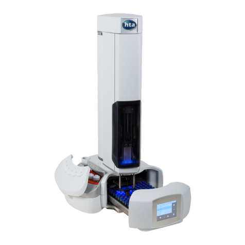
HTA HT2000H User manual

HT2000H_en_n.doc
User Guide
HT2000H, HT2100H, HT2000HT
Static Headspace GC Autosamplers
www.hta-it.com

HT2000H_en_n.doc 16/01/2018
This manual contains information about the product(s) indicated on the cover of this document.
The information contained in this document is subject to change without notice.
This document is for information only, the manufacturer accepts no liability for errors contained
herein or for incidental or consequential damage with the furnishing, performance, or use of this
material.
Unless otherwise specified, each reference to names or belongings is purely casual and has the
sole purpose of illustrating the product described here. Contents of this publication may not be
reproduced in any form or by any means (including electronic storage and retrieval or translation
into a foreign language), without prior agreement and written consent from the copyright owner.
All rights are reserved.
Manufacturer: HTA s.r.l. - 77-79, via del Mella, I-25131 Brescia (BS), Italy - Tel: +39 030 3582920 -
E-mail: info@hta-it.com

HT2000H_en_n.doc Page 3 of 167
Table of Contents
1
INTRODUCTION .......................................................................................................................8
1.1
I
NTENDED USE AND RESTRICTIONS
..........................................................................................8
1.2
S
YMBOL TABLE
.....................................................................................................................9
1.3
W
ARNING
...........................................................................................................................10
1.4
S
TANDARDS
C
OMPLIANCE
...................................................................................................13
1.5
G
ENERAL SPECIFICATION
.....................................................................................................14
1.6
F
UNCTIONS AVAILABLE ONLY THROUGH
HTA
A
UTOSAMPLER
M
ANAGER
....................................14
1.7
V
ERSIONS
..........................................................................................................................15
1.7.1
Description...................................................................................................................................... 15
1.7.2
Options............................................................................................................................................ 15
1.8
T
ECHNICAL
S
PECIFICATIONS
................................................................................................16
1.9
PC
SOFTWARE REQUIREMENTS
(HTA
A
UTOSAMPLER
M
ANAGER
).............................................19
2
EQUIPMENT DESCRIPTION...................................................................................................20
2.1
P
ARTS
D
EFINITION
..............................................................................................................20
2.1.1
HT2000H/HT2000HT Overview .....................................................................................................20
2.1.2
HT2100H Overview ........................................................................................................................ 25
2.1.3
Syringe location .............................................................................................................................. 28
2.1.4
Connection panel ............................................................................................................................ 30
2.2
M
OVING PARTS
...................................................................................................................32
2.3
T
OOL KIT
............................................................................................................................33
2.4
T
OUCH SCREEN DISPLAY DESCRIPTION
(HT2000H/HT2000HT) ..............................................34
2.4.1
Touchscreen use.............................................................................................................................. 34
2.4.2
Screen templates ............................................................................................................................. 35
2.4.3
Limited Warranty ............................................................................................................................ 42
3
INSTALLATION .......................................................................................................................43
3.1
U
NPACKING AND PRELIMINARY OPERATIONS
..........................................................................43
3.2
A
UTOSAMPLER ASSEMBLY
...................................................................................................44
3.2.1
How to lift and carry the autosampler ............................................................................................ 47
3.3
I
NSTALLATION
.....................................................................................................................48
3.3.1
Autosampler installation on the mounting plate ............................................................................. 48
3.3.2
Safety Lock setting .......................................................................................................................... 53
3.3.3
Electrical connections..................................................................................................................... 54
3.3.4
Purge line connections.................................................................................................................... 55
3.4
S
TART
-U
P
..........................................................................................................................56

HT2000H_en_n.doc Page 4 of 167
3.5
PC
CONNECTION AND SOFTWARE INSTALLATION
.....................................................................56
3.5.1
Autosampler controlled by LAN-connected PC ..............................................................................57
3.5.2
Autosampler connected directly to the PC ...................................................................................... 65
3.6
A
CCESSORIES INSTALLATION
................................................................................................66
3.6.1
External pressure regulator installation ......................................................................................... 67
3.6.2
Swagelok Adapter installation ........................................................................................................69
3.6.3
System integrity tool installation.....................................................................................................70
3.7
P
REPARING SAMPLE VIAL
.....................................................................................................72
3.7.1
Vial capping (Crimping Cap).......................................................................................................... 73
3.8
F
INAL INSTALLATION OPERATIONS
.........................................................................................74
3.9
B
ASIC TRAINING
..................................................................................................................74
4
SET UP OPERATIONS............................................................................................................76
4.1
V
IEW
P
ARAMETERS
.............................................................................................................76
4.2
S
ETUP
...............................................................................................................................77
4.2.1
Setup: Alignment.............................................................................................................................77
4.2.2
Setup: Syringe warmer assembly installation .................................................................................80
4.2.3
Setup: Manual operations............................................................................................................... 89
4.2.4
Setup: Configuration.......................................................................................................................92
4.2.5
Setup: Service.................................................................................................................................. 98
5
PROGRAMMING .....................................................................................................................99
5.1
HT2100H:
M
ETHODS AND
S
EQUENCE
..................................................................................99
5.2
HT2000H/HT2000HT:
M
ETHODS
........................................................................................99
5.2.1
Method Menu .................................................................................................................................. 99
5.2.2
Method X: Setting method parameters............................................................................................99
5.2.3
Method tools.................................................................................................................................. 103
5.2.4
Example ........................................................................................................................................ 103
5.3
HT2000H/HT2000HT:
S
EQUENCE
....................................................................................105
5.3.1
Sequence Menu ............................................................................................................................. 105
5.3.2
Setting sequence step parameters ................................................................................................. 105
5.3.3
Sequence tools............................................................................................................................... 106
6
HT2100H OPERATIONS .......................................................................................................107
6.1
K
EYS
...............................................................................................................................107
6.1.1
Keys Settings ................................................................................................................................. 108
6.2
S
TATUS
I
NDICATORS
.........................................................................................................108
6.2.1
Reference table.............................................................................................................................. 108

HT2000H_en_n.doc Page 5 of 167
7
HT2000H/HT2000HT OPERATIONS .....................................................................................111
7.1
H
OME SCREEN
..................................................................................................................111
7.1.1
Home screen: Standard User Interface......................................................................................... 111
7.1.2
Home screen: Quick Start User Interface ..................................................................................... 112
7.2
S
INGLE INJECTION
.............................................................................................................112
7.3
A
UTOMATIC RUN
...............................................................................................................113
7.3.1
Interrupting an automatic run....................................................................................................... 114
7.3.2
Immediate Injection....................................................................................................................... 114
7.3.3
Skip Next Vial option..................................................................................................................... 114
7.4
S
YRINGE PURGE
...............................................................................................................115
7.5
L
OAD AND
U
NLOAD
S
AMPLE
V
IAL
.......................................................................................115
7.6
S
ETTINGS
M
ENU
...............................................................................................................115
7.6.1
Change tray/rack type................................................................................................................... 116
7.6.2
Eco Savings ................................................................................................................................... 117
8
TROUBLESHOOTING ...........................................................................................................119
8.1
I
NTRODUCTION
.................................................................................................................119
8.2
S
TART UP ERRORS
............................................................................................................120
8.2.1
Safety lock error............................................................................................................................ 120
8.2.1
Vial locator error ...................................................................................................................... 120
8.2.2
Memory error................................................................................................................................ 120
8.3
M
ETHOD ERRORS
.............................................................................................................121
8.3.1
Fill Volume/Pull Up Strokes settings incompatibility ................................................................... 121
8.3.1
Fill volume/Syringe Pre-Fill settings incompatibility ............................................................... 121
8.4
T
OUCH
S
ENSOR PROBLEMS
...............................................................................................122
8.5
F
ALLING VIALS
..................................................................................................................122
8.6
O
BSTACLE FOUND
.............................................................................................................123
8.7
O
BSTACLE FOUND DURING COVER MOVEMENT
.....................................................................123
8.8
M
ISMATCH ERRORS
...........................................................................................................124
8.8.1
Single injection mismatch error .................................................................................................... 124
8.8.2
Automatic run mismatch errors .................................................................................................... 124
8.9
M
ISSING ERRORS
..............................................................................................................126
8.9.1
Missing: front injector alignment .................................................................................................. 126
8.9.2
Missing: rear injector alignment .................................................................................................. 126
8.9.3
Missing: touch & plunger zero...................................................................................................... 126
8.10
T
IMEOUT ERROR
...............................................................................................................127
8.10.1
Peripheral communication timeout ........................................................................................... 127

HT2000H_en_n.doc Page 6 of 167
8.11
M
ECHANICAL ERRORS
.......................................................................................................127
8.12
H
EATING ERRORS
.............................................................................................................128
8.13
O
VEN ERROR
...................................................................................................................128
8.14
S
YSTEM INTEGRITY TEST FAIL
.............................................................................................128
8.15
D
AMAGE TO SYRINGE NEEDLE
............................................................................................129
8.15.1
Syringe inspection ..................................................................................................................... 130
8.16
T
RAY EMERGENCY RELEASE
...............................................................................................131
8.16.1
Tray opening by hand ............................................................................................................... 131
8.17
“HTA
A
UTOSAMPLER
M
ANAGER
”
TROUBLESHOOTING
............................................................133
8.17.1
Autosampler and PC do not communicate (connection by LAN)............................................. 133
8.18
A
NALYTICAL TROUBLESHOOTING
.........................................................................................135
8.18.1
Reproducibility issue................................................................................................................. 135
8.18.2
Peak distortion or tailing .......................................................................................................... 136
8.18.3
Carry over issue........................................................................................................................ 136
8.18.4
Unexplained chromatographic peaks ....................................................................................... 136
8.18.5
Retention times not repeatable.................................................................................................. 136
8.18.6
Faulty temperature read-out..................................................................................................... 137
9
MAINTENANCE.....................................................................................................................138
9.1
O
RDINARY MAINTENANCE
..................................................................................................138
9.1.1
Cleaning of vial rack/tray ............................................................................................................. 138
9.1.2
External cleaning of cabinet ......................................................................................................... 139
9.1.3
Incubation oven cleaning .............................................................................................................. 139
9.1.4
Touch screen display cleaning ...................................................................................................... 140
9.1.5
Syringe replacement in the syringe warmer assembly .................................................................. 140
9.1.6
Septum of the System integrity tool replacement....................................................................... 150
9.1.7
Preventive maintenance pack.................................................................................................... 151
9.2
E
XTRAORDINARY MAINTENANCE
.........................................................................................151
10
UNINSTALLING AND DISPOSAL.......................................................................................152
10.1
A
UTOSAMPLER UNINSTALLING
............................................................................................152
10.2
A
UTOSAMPLER SHIPPING
...................................................................................................153
10.2
A
UTOSAMPLER DISPOSAL
...................................................................................................156
10.3
D
ISPOSAL INSTRUCTIONS
...................................................................................................156
11
APPENDIX A – GLOSSARY ..............................................................................................158
12
APPENDIX B – CONSUMABLES .......................................................................................160
12.1
S
YRINGES
........................................................................................................................160

HT2000H_en_n.doc Page 7 of 167
12.1.1
How to select the correct syringe type (only for HT2000HT)................................................... 160
12.2
S
AMPLE VIALS
..................................................................................................................161
12.2.1
Vial specifications..................................................................................................................... 161
12.2.2
Cap specifications..................................................................................................................... 164
12.2.3
Septa specifications................................................................................................................... 164
13
APPENDIX C – CONNECTION PANEL..............................................................................165
13.1
GC
CONNECTOR
...............................................................................................................165
13.1.1
Typical GC interface................................................................................................................. 166
13.2
RS232C
INTERFACE
(
OPTIONAL
)........................................................................................166

HT2000H_en_n.doc Page 8 of 167
1 Introduction
1.1 Intended use and restrictions
HT2000H, HT2100H and HT2000HT are static headspace autosamplers for gas
chromatography.
Headspace gas chromatography (GC) is a technique used for the concentration and analysis of
volatile organic compounds in almost any sample matrix.
The autosampler must be used in a professional environment, and only by properly trained
users. The autosampler must be used according to the regulations in force regarding the safety
in testing laboratories.
A list (not exhaustive) of typical applications of the autosampler is reported below:
•Environmental analysis
•Quality control in the chemical and pharmaceutical industry
•Studies related to pharmaceuticals
•Drug discovery
•Other techniques or areas of application are possible.
The safety measures and precautions regarding use, maintenance and repair, are not intended
for applications that require the use of toxic or infectious substances.
Every possible mixture or omission of a component cannot be recognized or previously
prevented. The operator that will use the autosampler must be trained about the used
substances, their hazards, their use and their proper disposal. For the correct use of the used
substances, refer to chemicals safety data sheets (MSDS) and to the regulations, laws,
directives and safety decrees currently in force that regulate the behaviour inside the testing
laboratories.
The insertion and positioning of the sample (vial), the insertion of syringes and all the other
preparation activities are under the sole responsibility of the user. The user must operate in
accordance with the law, in particular the ones concerning the safety of testing laboratories and
accident prevention.
The operator must be trained to operate the equipment in accordance with the safety standards
for the laboratories. The autosampler does not have specific protection mechanisms against
substances that are corrosive, potentially infectious, toxic and radioactive or against other
substances that can be hazardous to health. However, when the autosampler is used, because

HT2000H_en_n.doc Page 9 of 167
of the handled substances, the user could need to use individual protection measures such as
gloves, masks and goggles; the use of such devices must comply with the regulations currently
in force regarding the safety of testing laboratories.
The use of the autosampler for any technique invasive for humans or animals is explicitly
prohibited. The autosampler must be used only in the manner described in the usage
instructions. Any other use may affect the autosampler and operator safety.
HTA s.r.l. Is not responsible for damage caused, even only in part, by improper use of the
autosampler, by unauthorized modification of it, by different or missing execution of the
procedures described in this manual, or by the use of the autosampler violating the applicable
laws and regulations.
The autosampler has been designed and tested in accordance with current safety standards.
1.2 Symbol table
Please carefully read this table before using your autosampler. These symbols are used in this
manual.
Generic warning
Attention: dangerous voltage
Attention: mechanical hazard
Biological risks (if applicable for the substances used with the autosampler)
Hot surface

HT2000H_en_n.doc Page 10 of 167
1.3 Warning
Read the following warnings before unpacking or using the unit.
See paragraph 1.1 “Intended use and restrictions” and be sure you have understood
it.
See EU Declaration of Compliance enclosed with the autosampler.
Before removing the autosampler from the box, please carefully read paragraphs 3.1
“Unpacking and preliminary operations” and 3.2 “Autosampler assembly”.
Before switching the autosampler ON check the correct voltage.
Electrical Hazards. Every analytical instrument has specific hazards, so ensure you
read and comply with the following precautions.
Use only the power supply system supplied with the autosampler. The use of a
different system could cause damage to the equipment and/or compromise safety.
There are no operator-serviceable or replaceable parts inside the power supply. In
case of failure, contact the Technical Assistance Centre. Violations of these directives
imply the immediate invalidation of the warranty and service contract.
The supplied power cord must be inserted into a power outlet with a protective earth
contact (ground). When using an extension cord, make sure that the cord also has an
earth contact.
Do not change the external or internal grounding connections. Tampering with or
disconnecting these connections could endanger you and/or damage the
autosampler.
The product is designed and tested in accordance with international safety standards.
You do not need to make any changes to the electrical connections or to the chassis
of the autosampler in order to ensure safe operation.
Do not turn the autosampler on if you suspect that it has incurred any kind of electrical
damage or if it shows visible signs of damage. If, for any reason, the safety
protections were compromised or the autosampler shows visible signs of damage,
disconnect the power cord and contact an HTA representative. The power cord
connector is considered to be the disconnecting device of the product. Electrical
damage may have occurred if the autosampler shows visible signs of damage, or has

HT2000H_en_n.doc Page 11 of 167
been transported under severe stress.
The operator is responsible for the adequate decontamination in case of spilling of
dangerous substance over or inside the autosampler. The operator is also responsible
about the use of cleaning or decontamination agents. The agents shall not cause
hazard due to reaction with the autosampler or other materials contained inside. If
there are doubt about the use of cleaning or decontamination agents contact an HTA
representative.
With regards autosampler recycling and disposal the following operations have to be
performed: switch off the autosampler and remove syringe, samples and reagents,
eliminating any contamination of the instrument in accordance with national and
international safety regulations.
Damage can also result if the autosampler is stored for prolonged periods under
unfavourable conditions (e.g. subjected to heat, water, etc.).
Do not place the autosampler in a position which makes it difficult to handle the
disconnecting device of the autosampler.
Always disconnect the power cord before attempting any type of maintenance.
Capacitors inside the autosampler may still be charged even if the autosampler is
turned off.
The autosampler includes a number of integrated circuits. These circuits may be
damaged if exposed to excessive line voltage fluctuations and/or power surges.
If, for technical reasons, it is necessary to work on autosampler parts which are only
accessible using a tool, contact the Technical Assistance Centre. Violation of this
directive implies the immediate invalidation of the warranty and service contract.
These restrictions do not affect normal operations such as syringe installation and
removal.
Avoid contact with the autosampler while it is running.
Do not try to open or close the sample tray manually, unless it is strictly necessary. In
this case, follow the instructions of paragraph 8.16.1 “Tray opening by hand”.
To avoid accidents, observe the rules of good laboratory practice while handling
solvents, reagents and consumables. Observe the safety regulations regarding the
chemicals being used, as indicated in their specific Material safety data sheets
(MSDS). Carefully check the physical and chemical properties of the substances
before use.

HT2000H_en_n.doc Page 12 of 167
Do not use vials without sealing caps. Vapors from volatile solvents may be
hazardous and flammable. Acidic vapors may be corrosive for the mechanical parts.
The autosampler complies with section 15 of the FCC Rules. Operation is subject to
the following two conditions: (1) This device may not cause harmful interference, and
(2) this device must accept any interference received, including interference that may
cause undesired operation.
This autosampler has been tested and found to comply with the limits for a Class A
digital device, pursuant to section 15 of the FCC Rules. These limits are designed to
provide reasonable protection against harmful interference when the equipment is
operated in a commercial environment. This equipment can radiate radio frequency
energy and, if not installed and used in accordance with the instruction manual, may
cause harmful interference to radio communications. Operation of this equipment in a
residential area is likely to cause harmful interference in which case the user will be
required to correct the interference at his own expense.
If, during the start up process or while the running the machine, you notice unusual
noises or vibrations, stop the operating process and contact the Technical Assistance
Centre.
The warning signals stuck on the turret and on the oven cover indicate the presence
of moving parts, including the syringe and the fan in HT2000H/HT2000HT. Be careful
to avoid bumps or cuts.
The biohazard warnings present on the turret and on the oven cover indicates the
possible presence of biological or hazardous substances. This depends on the types
of substances used with the autosampler.
The autosampler can heat the vials in the oven and the sample in the syringe up to
170°C (HT2000H), 150°C (HT2100H) and 300°C (HT2000HT). For that reason the
oven and the syringe holder are labelled as hot surfaces. Be careful to avoid burns.
Allow the heated syringe adapter to cool down before attempting to change or inspect
the syringe. Do not touch the vials, without adequately protected hands, for at least 30
minutes after the vial is removed from the oven.
The autosampler can heat the vials in the oven and the sample in the syringe up to
170°C (HT2000H), 150°C (HT2100H) and 300°C (HT2000HT). The autosampler is not
intended to be used with a large quantity of flammable substances. Verify, according
to analysis of the laboratories safety standard and safety cards of chemical
substances, that substances can be used at this temperature without any risk to the
operator and/or the environment.

HT2000H_en_n.doc Page 13 of 167
The HT2000H/HT2000HT oven is equipped with a fan, which is used to assist
temperature stabilization and the cooling down of the oven.
This fan must not be obstructed as it may affect the operation of the unit.
The autosampler must be located in a place that provides good ventilation.
Environmental temperature must be from 15°C to 35°C and relative humidity must be
between 5-80% (not condensing). If these environmental conditions are not met, it
may affect the performance or damage the unit.
During headspace operation the syringe is cleaned after each injection with inert,
clean gas (e.g. N2 or He). Therefore a gas supply line must be available close to the
autosampler. Do not use flammable purging gases. Do not use hydrogen as a purging
gas. Hydrogen creates a potential explosion hazard due to the venting of gases.
Only for HT2000HT. Standard version syringe installed in the Standard syringe
warmer assembly can not work at temperature higher than 150°C. Do not set higher
temperatures. The system can be seriously damaged.
1.4 Standards Compliance
The applicable rules for this autosampler are the following:
•2014/35/EU Low-Voltage Equipment Directive.
•2014/30/EU Electromagnetic Compatibility Directive.
•2011/65/EU Restriction of the use of certain hazardous substances in electrical and
electronic equipment (RoHS) Directive.
•2006/42/EC Machinery Directive
HT2000H and HT2100H have been tested to and complies with the following safety standards:
•IEC 61010-1, Safety Requirements for Electrical Equipment for Measurement, Control and
Laboratory Use – Part 1:General Requirements.
•IEC 61010-2-010, Safety Requirements for Electrical Equipment for Measurement, Control
and Laboratory Use – Part 2-010:Particular Requirements for laboratory equipment for the
heating of materials.
•IEC 61010-2-081, Safety Requirements for Electrical Equipment for Measurement, Control
and Laboratory Use – Part 2-081:Particular Requirements for Automatic and
Semiautomatic Laboratory Equipment for Analysis and Other Purpose.

HT2000H_en_n.doc Page 14 of 167
In addition, HT2000H and HT2100H have been tested to and complies with IECEE CB Scheme,
including USA and Canadian national deviations. In particular the following standards are covered:
•UL 61010-1.
•CSA C22.2 No. 61010-1.
•EN 61010-1.
HT2000H and HT2100H have been tested to and comply with the following Electromagnetic
Compatibility (EMC) standards:
•EN 61326-1, EMC Requirements for Electrical Equipment for Measurement, Control and
Laboratory Use – Part 1: General Requirements.
•FCC CFR 47 Part 15, Code of Federal Regulations, Title 47 Part 15 Radio Frequency
Devices Subpart B, Unintentional radiation.
1.5 General specification
This is an autosampler for gas chromatography.
The autosampler is compatible with most Gas Chromatographs (GC).
It can be installed on GCs with both one and two injectors.In the case of GCs with two injectors,
your autosampler can be configured to inject automatically into one or the other injector.
The sample vials are transported into the oven for preconditioning. The sample is heated and
simultaneously shaken in order to facilitate the state change and reach the equilibrium, then a
heated gas-tight syringe is moved over the incubator and the headspace sample is withdrawn.
After sample injection the syringe is automatically cleaned by purging with inert gas.
The autosampler can be programmed by using the touch screen display (only for HT2000H and
HT2000HT versions) or by a PC using an Ethernet or RS232C connection (optional).
1.6 Functions available only through HTA Autosampler
Manager
Vial Leakage Check
HTA Autosampler Manager allows the user to enable the Vial Leakage Check (ACCESS
SEQUENCE: Setup-Options).
If this option is enabled, the pressure inside vials is monitored by an heuristic procedure in order to
check against anomalous values that are indicative of a vial leakage problem.
The Vial leakage test can discriminate for samples which are correctly sealed vs. bad crimping or
missing septa. Each sample is marked with PASS or FAIL information in HTA Autosampler
Manager windows.

HT2000H_en_n.doc Page 15 of 167
Method development option
During method development it can be useful to test methods characterized by a progressive
increment of a specific parameter in order to define which are the best settings for this parameter.
The parameters that can be increased in this way are the syringe/oven temperature and the
incubation time.
This option is only available with “HTA Autosampler Manager”, using the “Method development”
tab. For the detailed explanation of this option, please refer to “HTA Autosampler Manager” online
help.
1.7 Versions
1.7.1 Description
The autosampler is available in the following versions:
HT2000H
This version is equipped with a touch screen interface.
It has a moving tray with 42 vial positions.
It has a 6 position oven (incubation temperature up to 170°C) equipped with an orbital shaker
HT2100H
This version is equipped with a keypad.
It has a fixed tray with 14 vial positions.
It has 1 position oven (incubation temperature up to 150°C) with a sussultatory shaker.
Require a PC for set up, service, method and sequence editing.
HT2000HT
This version is equipped with a touch screen interface.
It has a moving tray with 42 vial positions.
It has a 3 position oven (incubation temperature up to 300°C) equipped with an orbital shaker.
1.7.2 Options
Available for all versions:
1.90.501 - HTA Autosampler Manager (Standard Version)
PC software. This may be sold as an option. Please check with your service representative.
1.90.502 - HTA Autosampler Manager (CFR 21 Part 11)
PC software compliant with CFR 21 Part 11 regulation. This may be sold as an option. Please
check with your service representative.
1.91.295 - System integrity kit
The System integrity kit is sold as an option. The System integrity test is used to verify the syringe
integrity. This test can easily be executed at the beginning of each batch in a very convenient way.

HT2000H_en_n.doc Page 16 of 167
This functionality is made in a heuristic approach (for detailed description of this function see
paragraph 11 “Appendix A – Glossary”).
The following accessories can be supplied upon request:
HTA Part Number Description
3.23.000 External Pressure Regulator
1.93.822 Swagelok adapter for HT2x00x serie
1.93.820 Spacers kit for 10ml vial (6pc/pk) (only for HT2000H)
1.93.821 Spacers kit for 10ml vial (15pc/pk) (only for HT2100H)
1.93.828 Spacers kit for 6ml vial (6pc/pk) (only for HT2000H)
1.91.280 Syringe kit 1ml for Headspace autosampler
3.20.010 Syringe kit 5ml for Headspace autosampler
1.91.330 Syringe Warmer High Temperature (Assembly) for HT2000HT
1.93.824 System integrity kit (Headspace)
C00028 Manual Crimper for 20mm Caps
C00029 Manual De-Crimper for 20mm Caps
1.8 Technical Specifications
DIMENSIONS
HT2000H/HT2000HT
Height 640mm
Width (closed oven cover) 330mm

HT2000H_en_n.doc Page 17 of 167
Width (open oven cover) 350mm
Depth (closed tray) 320mm
Depth (open tray) 520mm
HT2100H
Height 640mm
Width 280mm
Depth 320mm
WEIGHT
HT2000H/HT2000HT 10kg
HT2100H 8kg
ELECTRICAL SPECIFICATIONS
Power supply:
Voltage 100-240 ±10%Vac
Frequency 50-60Hz
Max Current 1.6 A (HT2000H/HT2000HT); 1.4-0.7 (HT2100H)
Autosampler HT2000H/HT2000HT:
Voltage 24Vdc
Power 120W
Autosampler HT2100H:
Voltage 24Vdc
Power 60W
INTERFACE SPECIFICATIONS
To GC TTL
To PC Ethernet 10/100
Optional: RS232C (available on a limited number
of models)
Ethernet cable should be Category 5 (or higher)
RS232 cable: max distance PC – autosampler: 1.80m (opt. 3.50m)
ADDITIONAL REQUIREMENTS (for HT2100H only)
HT2100H requires a PC for set up, service, method and sequence editing

HT2000H_en_n.doc Page 18 of 167
ENVIRONMENT CONDITIONS
Room temperature limits 15°C - 35°C
Ambient humidity limits 5% - 80% (not-condensable)
Maximum altitude 2000m
SOUND PRESSURE LEVEL
Maximum measured level 60dBA (below the limits of 85dBA defined
by the regulations in force)
SAFETY INFORMATION
The autosampler is classified as shown below:
Pollution degree 2
Overvoltage category II
Devices for use indoors
TRAY AND SYRINGE FEATURES
Tray capacity 42 vial positions (HT2000H and HT2000HT)
14 vial positions (HT2100H)
Syringe volume 1-2.5-5ml
Maximum pressure in the injector 5 bar
(2.5ml syringe)
ANALYTICAL PARAMETERS
Conditioning
HT2000H
Oven positions 6
Oven Temperature off, from 40°C1 to 170°C
Incubation time from 0 to 999min step 1min
Shaking method orbital
Shaker speed from very low to very high
Shaking cycles on/off, from 0 to 9.9min
HT2100H
Oven positions 1
Oven Temperature off, from 40°C2 to 150°C
Incubation time from 0 to 999min step 1min

HT2000H_en_n.doc Page 19 of 167
Shaking method sussultatory
Shaker speed from very low to very high
Shaking cycles on/off, from 0 to 9.9min
HT2000HT
Oven positions 3
Oven Temperature off, from 40°C3 to 300°C
Incubation time from 0 to 999min step 1min
Shaking method orbital
Shaker speed from very low to very high
Shaking cycles on/off, from 0 to 9.9min
Sampling
Syringe Temperature off, from 40°C to 150°C (standard version
syringe) or 250°C (HT version syringe installed
on HT2000HT)
Sample volume 0.01ml stepwise
Pull Up Strokes up to 15 strokes
Sample speed from 0.1 to 100ml/min (40ml/min for 1ml syringe)
Injection
Injection speed from 0.5 to 100ml/min (40ml/min for 1ml
syringe)
Pre/Post injection dwell time from 0 to 99s
Enrichment cycles up to 15
Dwell time between enrichment cycle from 0 to 100min
Syringe purge
Flush time from 0 to 99min
Purge temperature off, from 40°C to 150°C (standard version
syringe) or 250°C (HT version syringe installed
on HT2000HT)
1.9 PC software requirements (HTA Autosampler Manager)
See HTA Autosampler Manager Online Help for the related PC specifications.

HT2000H_en_n.doc Page 20 of 167
2 Equipment Description
2.1 Parts Definition
2.1.1 HT2000H/HT2000HT Overview
2.1.1.1 HT2000H/HT2000HT Main parts
Figure 1: HT2000H/HT2000HT
(tray open) top view
Figure 2: HT2000H/HT2000HT
(tray closed) top view
6
4
5
2
1
3
6
4
2
5
1
3
This manual suits for next models
2
Table of contents
Other HTA Laboratory Equipment manuals