AC input overvoltage, undervoltage,
open phase, or serious voltage
imbalance
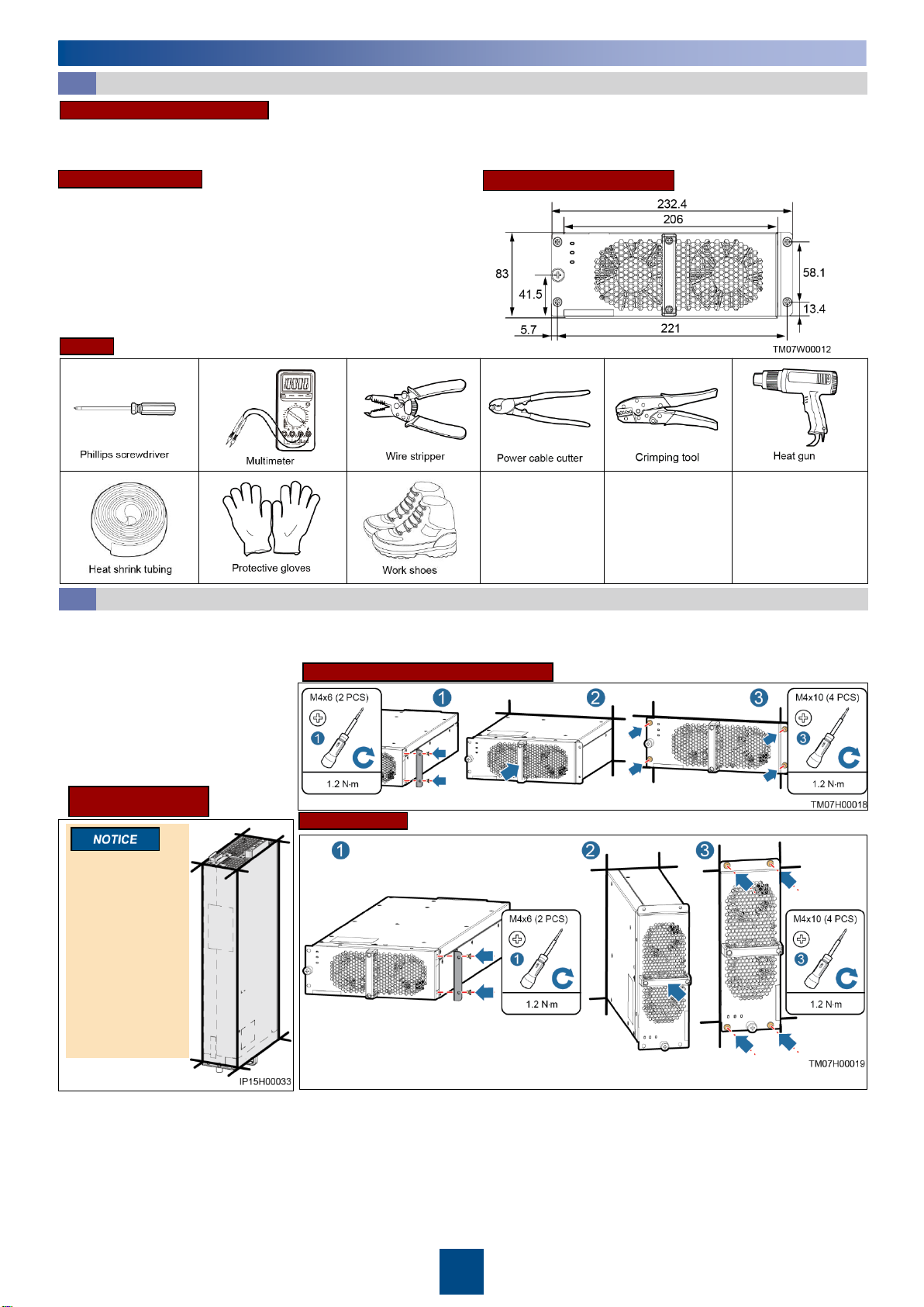
Model R95021G1
Weight •12 kg (without packaging)
•14 kg (with packaging)
Dimensions (H x W x D) 83 mm x 206 mm x 470 mm
Front
Rear
Copyright © Huawei Technologies Co., Ltd. 2018. All rights reserved.
1.The information in this document is subject to change due to version upgrades or other reasons. Every effort has been made in the
preparation of this document to ensure accuracy of the contents, but all statements, information, and recommendations in this document do
not constitute a warranty of any kind, express or implied.
2.Before installing the device, carefully read the user manual to get familiar with product information and safety precautions. You can log in to
http://support.huawei.com/enterprise/ and search for the device model on the Product Support tab page to view or obtain the user manual.
3.Only qualified and trained electrical technicians are allowed to operate the device. Operation personnel must wear proper personal protective
equipment (PPE) all the time.
4.The charger module does not have the battery reverse-connection prevention function. The charging machine (pile) needs to detect battery
reverse-connection prevention. The module failure caused by battery reverse-connection is not covered under the warranty.
5.When operating Huawei equipment, follow the precautions and special safety instructions provided by Huawei. Huawei will not be liable for
any consequences that are caused by the violation of safety regulations and design, production, and usage standards.
6.Do not remove the warranty label or barcode from the charger. Otherwise, product warranty will be forfeited.