Huawei NetCol5000-A050 User manual

1Overview
1
Category Product Model Dimensions Without Packing (mm) (H x
W x D)
Indoor unit NetCol5000-A050 2000 x 600 x 1200
Outdoor unit
NetCol500-A060(52273539) 1107 (677) x 1356 (1217) x 1094
NetCol500-A060(52273539-005) 1107 (655) x 1356 (1217) x 1094
NetCol500-A060(52273539-006) 1156 (703) x 1356 (1217) x 1094
NetCol500-A080(52273541-005) 1107 (655) x 2186 (2047) x 1094
NetCol500-A120(52273755-002) 1107 (655) x 1356 (1217) x 2188
Water-cooled
module NetCol500-W055 530 x 1510 x 262
①You can view the outdoor unit code on the equipment barcode.
The quick guide describes how to install the indoor units, outdoor units, and water-cooled
modules.An indoor unit is used with an outdoor unit or a water cooled module.
Issue: 10
Part Number: 31500BLX
Date: 2022-07-15
NetCol5000-A050 In-row Air Cooled Smart
Cooling
Quick Guide
Before installation, read the user manual carefully to get familiar with product information and
safety precautions.
①
Copyright © Huawei Technologies Co., Ltd. 2022.
All rights reserved.

2
Man-
datory
Refrigerant
pipe
Gas pipe requirements: outer diameter of 7/8 inch (22.22 mm) ; thickness of
1.2 mm; operating pressure ≥ 4.5 MPa
Liquid pipe:
L ≤ 60 m: outer diameter of 5/8 inch (15.88 mm) ; wall thickness of 1.0 mm;
operating pressure > 4.5 MPa
60 m < L ≤ 100 m: outer diameter of 3/4 inch (19.05 mm) ; wall thickness of
1.0 mm; operating pressure > 4.5 MPa
Thermal insulation foam: thickness ≥ 9.2 mm
Oil trap and inverted trap,and refrigerant pipe supports
Water pipe Humidifier water inlet pipe (optionally configured for the humidifier and the
humidifier hose is provided for the smart cooling product)
•Rigid pipe: G 1/2 inch rigid pipe connector with external thread, rigid pipe
(such as PP-R pipe)
•Hose: G 1/2 inch pagoda connector with external thread, hose (such as
EPDM pipe)
Humidifier water inlet pipe (optionally configured for the humidifier and the
humidifier hose is not provided for the smart cooling product): (PP-R and
other pipes) active connector: G3/4 inch internal thread, rigid pipe, elbow
Drainpipe:
•Rigid pipe: BSPT 1/2 inch rigid pipe connector with external thread, rigid
pipe (such as PP-R pipe)
•Hose: BSPT 1/2 inch pagoda connector with external thread, hose (such as
EPDM pipe)
Water-cooled module: cooling water supply and return pipes, steel pipes
having G1-1/2 inch connectors with external threads
Thermal insulation foam: thickness ≥ 9.2 mm
Cable
specificati-
ons
•Indoor unit power cable: 5 x 10 mm2
•Outdoor unit power cable: 5 x 2.5 mm2 (Do not use the N wire onsite.)
•Equipotential ground cable: 6 mm2outdoor copper cable
•Power cable for the water-cooled module: 3 x 1.5 mm2
•(Optional) Power cable of the low temperature component: 2 x 1.5 mm2
•(Optional) Signal cable between the indoor and outdoor units: 3 x 1.5 mm2
,
Electrical power cable, 300 V, SJTW, 3 x 16 AWG, black (three cores: black,
white, and green), 10 A, shielded outdoor cable, UL
Optio
nal
Cable and
base
Temperature and humidity (T/H) sensor outside the cabinet and cable;
determined based on scenarios: indoor unit base, outdoor unit support or
concrete base, and water-cooled module concrete base
2Onsite Preparations
1. The signal cable for the indoor and outdoor units
is mandatory when the outdoor unit is equipped
with an intelligent temperature control
monitoring board.
2. The shield layer of signal cable must be grounded.
3. Do not use shielded cables as outdoor unit power
cables.

3
Refrigerant R410A
2.1
Do not use inferior refrigerant. Otherwise, Huawei has no responsibility for the damage caused
by the inferior refrigerant.
Refrigerant authenticity verification method:
1. Dial the hotline of the refrigerant producer to confirm its reliability.
2. Put the refrigerant indoor for 24 hours. Then use a thermometer to measure the external
surface temperature of the refrigerant cylinder (figure 1) , and connect a pressure gauge to
the cylinder to measure its internal pressure (figure 2) . Look up the following table for the
saturation pressure that corresponds to the external surface temperature, and calculate the
deviation from the internal pressure. If the deviation is more than 0.2 MPa, the refrigerant is
not in good condition. Replace it.
Mapping Between Saturation Temperatures and Pressure of R410A
Saturation
temperature (ºC)
Gauge
(MPa)
Saturation
temperature (ºC)
Gauge
(MPa)
Saturation
temperature (ºC)
Gauge
(MPa)
10 0.99 19 1.31 28 1.69
11 1.02 20 1.35 29 1.74
12 1.05 21 1.39 30 1.79
13 1.09 22 1.43 31 1.84
14 1.12 23 1.47 32 1.89
15 1.16 24 1.51 33 1.94
16 1.19 25 1.56 34 1.99
17 1.23 26 1.60 35 2.05
18 1.27 27 1.65 36 2.10
3Checking the Nitrogen Pressure
Liquid
pipe
needle
valve
Low-
pressure
needle
valve Discharge
pipe
needle
valve

Refrigerant side needle valve
Cooling water side
needle valve
4
Removing the Pallet
4.1 Removing Transport Fasteners
from the Compressor
4.2
1. Read the related user manual or instructions before installing the NetCol5000-A.
2. The unit in this document is a fully configured NetCol5000-A. If some components are not
configured, skip the corresponding steps.
3. You are recommended to use tools that are fully insulated when installing devices.
4. Only engineers from the manufacturer or engineers certified by the agent are allowed to
install, commission, and maintain smart cooling product. Otherwise, personal injuries and
device damage may be caused, which is beyond the smart cooling product warranty range.
4Installing the Indoor Unit
1. If they do not exist, contact Huawei technical support.
2. Connect the hose to the pressure gauge, and tighten all pressure gauge valves.
3. Remove the needle valve bonnet, and connect the other end of the hose to the needle valve.
4. If the pressure gauge reading is no less than 0.2 MPa, the unit is airtight. Then open the
pressure gauge valve where the hose is connected to discharge nitrogen. After the discharge is
complete, remove the hose and reinstall the valve bonnet.
5. If the pressure gauge reading is less than 0.2 MPa, pipes have leakage points, and you need to
contact Huawei technical support.

5
Level
Leveling a Cabinet
4.3 Combining Cabinets
4.4
Securing to the Floor or Base
4.5 Installing Sealing Plates to the
Front and Rear Doors
4.6
Sealing plates are not in the fittings bag of the smart cooling product but supplied by the smart
module or purchased independently.

6
5(Optional) Installing the Outdoor Unit
•The protective cardboard for fins must be removed after installation to protect people from
injuries.
•The installation methods of installing NetCol500-A060 and NetCol500-A080 outdoor units
are the same. This section describes how to install a NetCol500-A060.
•If the space does not meet the requirements of the recommended layout, you can use any of
the following layouts.
Make sure that no blockage is above the outdoor unit.
Unit: mm
Scenario 1: Horizontal installation top view Scenario 2: Vertical installation top view
a. Remove the angle brackets.
Horizontal Installation
5.1
b. Install the four legs.

7
c. Secure the legs to the concrete base.
Unit: mm
Model
Distance
Between the
Centers of Two
Platforms at
the Length
Side (W)
Distance
Between the
Centers of
Two
Platforms at
the Length
Side (D)
NetCol500-A060 924 1047
NetCol500-A080 924 1877
NetCol500-A120 2018 1047
Vertical Installation
5.2
Unit: mm
Model
Distance between
the Centers of
Two Platforms at
the Length Side
(W)
NetCol500-A060
(52273539, 52273539-
005)
1036.5
NetCol500-A060
(52273539-006)977
NetCol500-A080 1744.5
NetCol500-A120 2011

8
6(Optional) Installing the Water-Cooled Module
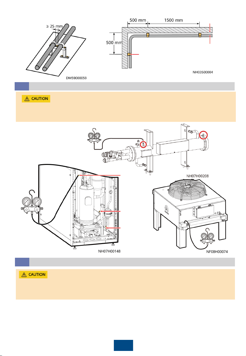
7Connecting the Refrigerant Pipes
Laying the Engineering Pipes
7.1
1. When an outdoor unit is installed horizontally, the outdoor unit and the low temperature
component must be at the same horizontal plane. When the outdoor unit is installed vertically,
the installing horizontal plane of the outdoor unit must not be lower than that of the low
temperature component, and the height difference cannot exceed 1.5 m.
2. When calculating the height difference, the compressor base is regarded as the baseline for
the indoor unit, and the condenser top is regarded as the baseline for the outdoor unit. The
pipe length must be less than or equal to 100 m.
3. The inverted trap should be higher than the top copper pipe of the condenser.
4. When the indoor unit is higher than the outdoor unit, the maximum height difference is 8 m.
When the indoor unit is lower than the outdoor unit, the maximum height difference is 30 m.
5. When welding pipes, ensure that the pipes are dry. You are recommended to weld the pipes
between the indoor and outdoor units, then connect the two ends of the pipe to the indoor
unit and outdoor unit.
6. Connect one end of the rubber hose to the nitrogen cylinder with a reducing valve, and
connect the other end to the copper pipe. Then, fill 0.03–0.05 MPa nitrogen into the copper
pipe to avoid internal oxidation.
7. After the pipe in the middle is welded, charge nitrogen into the pipe from one pipe end to
clear the foreign matter inside.
8. Do not expose welding positions to the environment for a long time. Take sealing measures
for welding positions. If foreign matter exists at the welding position, rubber it out using non-
water alcohol or damp cloth before the welding.
9. If the indoor unit is placed lower than the outdoor unit, add an inverted U-shaped trap. To
ensure the NetCol5000-A reliability, make an oil trap every 5 m to 6 m along pipes in the
vertical direction.
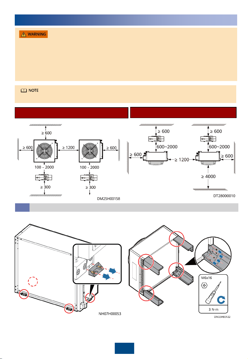
Scenario 2: Horizontal concrete base installation
Scenario 3: Stack scenario
A maximum of four layers of water-cooled modules can be stacked. If four layers of water-cooled
modules are stacked, the minimum floor height is 3 m.
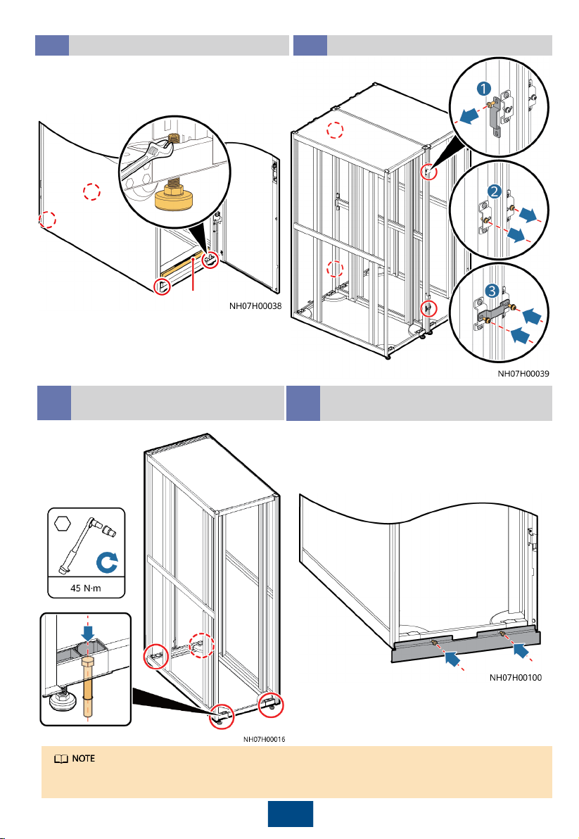
Secure the water-cooling module using bolts in the fitting bag on four mounting holes.
Scenario 1: Horizontal
installation top view
Installation environment: enclosed indoor environment in which the temperature and humidity can
be controlled within the ranges of 4°C to 45°Cand 5% RH to 90% RH respectively. If the indoor
installation position is ventilated, it should be more than 5 km away from the sea or pollution
sources (such as salt lakes, chemical plants, mineral plants, thermal power plants, and coal mines).
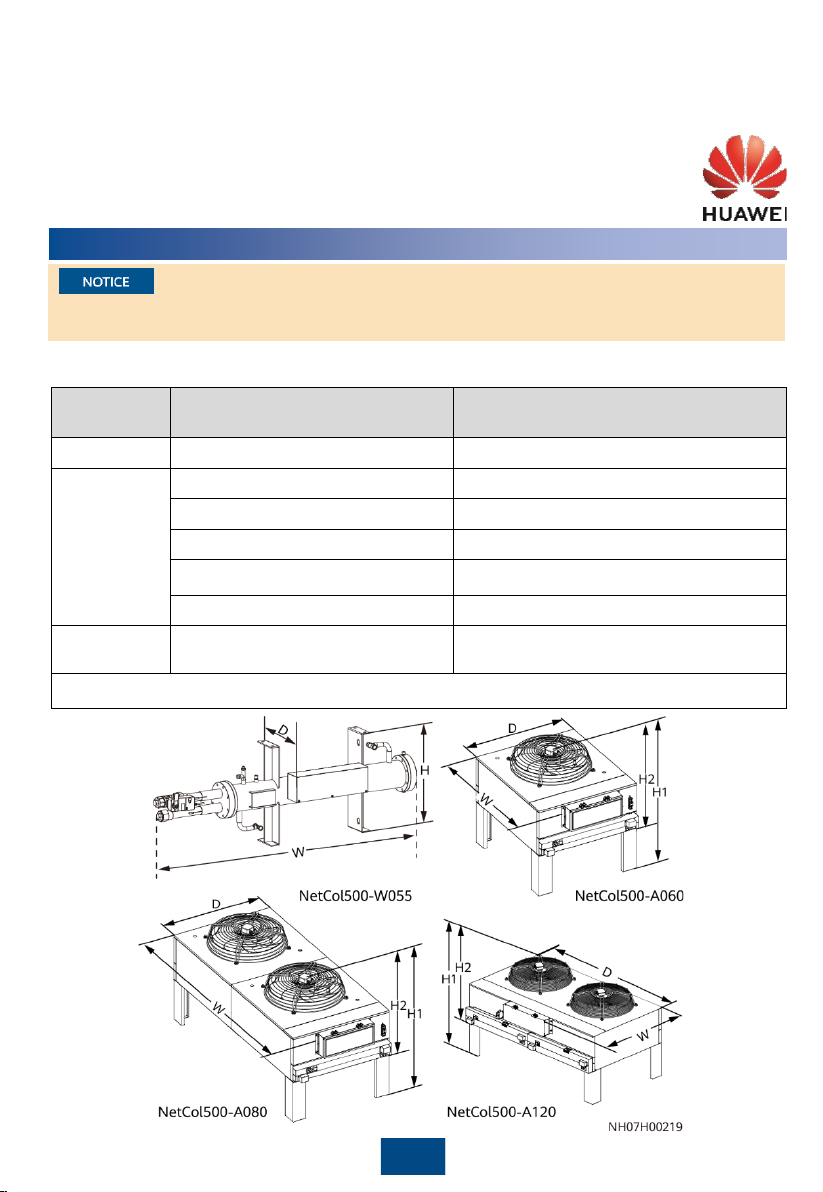
Unit: mm

Pipe
Pipe support
Wall
9
Discharging Nitrogen
7.2
Separately exhaust nitrogen from the three needle valves. Separately exhaust nitrogen from
the two needle valves for the water-cooled module. When exhausting nitrogen, do not
remove the valve plug in case of losing or damaging it.
Liquid pipe
needle
valve
Low-
pressure
needle
valve
Discharge
pipe needle
valve
Take protective measures, such as spreading a piece of wet cloth, around the welding position,
to avoid burning the bottom panel, top panel, side panel, internal components, needle valves,
other pipes, thermal insulation foam, power cables, labels, and tags.
Welding the Indoor Unit Ports
7.3

10
Top pipe routing
5/8 inch
liquid pipe
7/8 inch
gas pipe
Thermal
insulation foam
5/8 inch
liquid pipe
7/8 inch
gas pipe
Thermal
insulation foam
Bottom pipe routing
•When the outdoor unit is
installed vertically, the gas
pipe should be connected to
the top port and the liquid
pipe should be connected to
the bottom port.
•A reducing pipe is required
when welding a 3/4 inch
copper pipe to a 5/8 inch
connector.
Thermal
insulation foam
5/8 inch liquid pipe
7/8 inch gas pipe
Welding the Outdoor Unit Ports
7.4

11
To indoor unit
liquid pipe To indoor unit gas pipe
To outdoor unit gas pipe
To outdoor
unit liquid
pipe
(Optional) Welding the Low
Temperature Component Pipes
7.5 Welding the Water-Cooled
Module
7.6
5/8 inch
liquid pipe
7/8 inch
gas pipe
8Connecting Water Pipes
(Optional) Connecting the Humidifier Water Inlet Pipe
8.1
1. Clean the water inlet engineering pipes to avoid
impurities entering into the humidifier.
2. When routing pipes from the top, do not route the pipes
over servers or other devices to protect them from being
affected by pipe leaks.
3. Wrap each part of the pipes with thermal insulation
foam.
4. Use supports to secure pipes.
Connection method
Top pipe routing
Bottom pipe routing
(1) Reserved connector (7) Reserved connector
(2) Rigid pipe conversion
adapter
(8) Active connector
(3) Rigid pipe (9) Rigid pipe
(4) Pagoda connector (10) Elbow
(5) Hose clamp (11) Rigid pipe
(6) Hose

Top pipe routing Bottom pipe routing
In the automatic drainage scenario, you
do not need to perform the first step.
•If a humidifier water inlet hose is
delivered with the smart cooling
product, pull the hose out of the
smart cooling product and
connect the hose, as shown in
Figure 1. For details, refer to
connection methods A and B.
•If a humidifier water inlet hose is
not delivered with the smart
cooling product, connect the
water pipe to the reserved port
of the smart cooling product as
shown in Figure 2 by referring to
connection method C.
Connecting the Drainpipe
8.2
Connection method
(1) Inner-threaded connector (use the sealant for
screw threads)
(2) Adapter
(3) Rigid pipe
(4) Pagoda connector
(5) Hose clamp
(6) Hose
The drainpipes must have gradients (> 1: 100) ,
and stagnant water is not allowed.
12

Connecting the Water Supply and Return Pipes of the Water-Cooled Module
8.3
Connecting the steel pipe
Performing a Leakage Test with Water for the Water-Cooled Module
8.4
Manually open the water valve. Inject water to 0.8 MPa and
preserve the pressure for 24 hours. Connect the pressure
gauge to the cooling water side needle valve and measure
the pressure gauge reading. If the reading remains
unchanged, the pipe is not leaking. You can perform the
following operations.
(1) Reserved device port
(2) Steel pipe
9Installing Cables
1. The power cables and signal cables should be separately bound.
2. The shielding layer of signal cable must be grounded.
3. In bottom cabling, if it is hard to bend a cable 90°, disassemble the cable and fix it using the
pipe clamp. As the PE cable is long, prepare the five-core cable based on the length of the PE
cable.
4. The recommended upstream switch is C63 or higher.
5. The outdoor unit, indoor unit, and water-cooled module must receive power from the indoor
unit.
6. Retain the outer insulation layer when routing the cable through the waterproof connector.
7. Power cables and ground cables are routed and bundled separately from other types of
cables.
(1) Refrigerant side needle valve
(2) Cooling water side needle valve
13

Connecting the Indoor Unit Power Cable and Equipotential Ground Cable
9.1
Equipotential ground ports Equipotential ground ports
Single power
supply
Dual power
supplies
Equipotential ground ports Equipotential ground ports
Single power supply
Dual power
supplies
Top cable routing
Bottom cable routing
14

1. Outdoor units of different models have different electric control box layout but the same port
silk screen.
2. The following figure shows the cable routing in bottom cabling mode. In top cabling mode,
you can route cables through the holes shown in the figure.
3. The outdoor cables are sun-and water-proofed. It is recommended that tubes be used for
protection.
4. When the outdoor unit is NetCol500-A120, two indoor units can be connected.
5. The power and signal cables are routed in accordance with the electric and ELV cable routing
specifications and the cable routing plan.
6. The signal cable for the indoor and outdoor units is mandatory when the outdoor unit is
equipped with an intelligent temperature control monitoring board.
Connecting the Outdoor Unit Power Cable and (Optional) the Signal Cable
Between Indoor and Outdoor Units
9.2
15
(1) Equipotential ground position
(2) Equipotential bottom cable hole
(3) Equipotential top cable hole
If the indoor unit BOM number is 52274052, connect the indoor units power cable and
equipotential ground cable as shown in the following figure.

16
Power cable hole
Signal cable hole
Outdoor unit power cable
on the side of the indoor
unit
Outdoor unit
power cable
Connecting the Power Cables to the Outdoor Units
If the outdoor unit is NetCo500-A120, connect the power cables of the two indoor units to
the QF1 and QF3 of the outdoor unit respectively.
Power
cable hole
Outdoor unit
power cable
Outdoor unit
power cable on the
side of the indoor
unit
If the indoor unit BOM number is 52274052, connect the outdoor unit power cable as shown
in the following figure.

17
Signal cables for the indoor units
Signal cable hole
Signal cables for the outdoor units
Power cable hole
(Optional) Connecting the Signal Cable Between Indoor and Outdoor Units
Perform this operation only for outdoor units configured with an intelligent monitoring board.
The outdoor units are 52273539.
Connecting the Low Temperature Component Power Cable
Low temperature
component power
cable
Power cable between
indoor and outdoor
units
Signal cable
hole
Power cable hole
Low temperature component
Low temperature
component/Water
-cooled module
•If the outdoor unit is NetCo500-A120, connect the power cables of the two indoor units to
the QF2 and QF4 of the outdoor unit respectively.
•The label is "Receiver heater/Water-cooled module" or "Low temperature
component/Water-cooled module". The actual label may vary.

18
Connecting the Power Cable and Signal Cable for the Water-Cooled Module
Power cable hole
Signal cable hole
Water-
cooled
module
Water-cooled
module
Signal cables for
the indoor units
Water-cooled module
power cable on the
side of the indoor unit
Connecting T/H Sensors Outside Cabinets
9.3
1. Connect the T/H sensor cables.
The T/H sensors in the aisles should be
installed on the door frame of IT cabinets,
and 1.5 m (33 U) away from the ground.
After the sensor is secured, set the sensor
address according to the following table.
2. Set the DIP switches on the T/H sensors.
Name Address DIP Switch ID
123456
Cold aisle 1 temp/humid 11 ON ON OFF ON OFF OFF
Cold aisle 2 temp/humid 12 OFF OFF ON ON OFF OFF
Cold aisle 3 temp/humid 13 ON OFF ON ON OFF OFF
Cold aisle 4 temp/humid 14 OFF ON ON ON OFF OFF
Cold aisle 5 temp/humid 15 ON ON ON ON OFF OFF
Hot aisle 1 temp/humid 21 ON OFF ON OFF ON OFF
Hot aisle 2 temp/humid 22 OFF ON ON OFF ON OFF
Hot aisle 3 temp/humid 23 ON ON ON OFF ON OFF
Hot aisle 4 temp/humid 24 OFF OFF OFF ON ON OFF
Hot aisle 5 temp/humid 25 ON OFF OFF ON ON OFF

(Optional) Connecting the Teamwork Network Cable
9.4
19
Ports on the Main Control Module
No. Name Description
1Running indicator -
2Alarm indicator -
3FE_1 port FE teamwork control
4CAN_IN port CAN teamwork and RS485 monitoring cascading
5RS485/12V port Connecting to a T/H sensor
6USB port Connecting to a WiFi module or USB flash drive
7SW button Button for restoring factory settings
8FE_2 port FE teamwork control
9CAN_OUT port CAN teamwork and RS485 monitoring cascading
10 COM/FE port Connecting to a monitoring communications cable
11 DP port Connecting to the display
a) Prepare network cables.
PIN Color FE_1 and
FE_2
CAN_IN and
CAN_OUT
RS485/12V
Port
COM/FE
Port
(FE
Monitoring)
1White-and-
orange FE TX+ RS485 T+ (+) RS485 HT+FE TX+
2Orange FE TX–RS485 T– (–) RS485 HT–FE TX–
3White-and-
green FE RX+ -12V FE RX+
4Blue -RS485 R+ RS485 HT+RS485+
5White-and-
blue -RS485 R–RS485 HT–RS485–
6Green FE RX–- - FE RX–
7White-and-
brown -CANH - -
8Brown -CANL GND -
PIN Color COM/FE Port (RS485
Monitoring)
4Blue RS485+
5White-and-blue RS485–

20
Smart Module Networking Scenario
Networking Teamwork Monitoring
Protocol MAC_CAN Modbus-
TCP
b) Connect teamwork and monitoring communications cables.
CAN Teamwork + RS485 Monitoring
Networking Teamwork Monitoring
Protocol CAN Modbus-TCP
Description
One teamwork network
supports a maximum of
32 units. On the
Teamwork Settings
screen of the display
modules of the first and
last units, set Enable
teamwork CAN resistor
to Yes.
It takes 3 x n seconds to collect data from n units. If the
time required for the host to collect data from all units
does not meet the performance requirements, group the
units.
•If units are not grouped (n = 1), set RS485
monitoring grouping to Enable on the Modbus
Settings screen for each unit.
•If units are grouped (n > 1; recommended: n ≤ 4), set
RS485 monitoring grouping to Enable on the
Modbus Settings
screen for the unit with the COM/FE
port connected. Retain the default setting (Disable)
for other units.
Connect the
COM/FE port on the
main control
module of the last
smart cooling
product in each
group to the RS485
port on the host.
Other manuals for NetCol5000-A050
5
This manual suits for next models
9
Other Huawei Cooling Box manuals
Popular Cooling Box manuals by other brands

Baltimore Aircoil Company
Baltimore Aircoil Company V Series Operating and maintenance instructions

Rittal
Rittal SK 3178800 Assembly and operating instructions

Selecta
Selecta REFRICUB instruction manual

Bühler technologies
Bühler technologies CU-EMA+ Assembly, installation and operation instructions

Trane
Trane TR-SCS Series Installation, operation and maintenance

Dometic GROUP
Dometic GROUP Waeco TropiCool TB-W203 operating manual