Baltimore Aircoil Company V Series Manual

altimore Aircoil Company Series V equipment
has been designed to give long, trouble-free
service when properly installed, operated, and
maintained. To obtain optimum performance and
maximum service life, it is important that a program of
regular inspection and maintenance be developed and
carried out. This bulletin is published as a guide to
establishing such a program.
Included in the bulletin are the recommended services
for start-up, operation, and shutdown and the approxi-
mate frequency for each. Note that the recommen-
dations on frequency of service are minimums and
where operating conditions are severe, the services
should be performed more often. For each required
service, follow the procedures outlined under the
“Maintenance Procedures” section of this bulletin. The
VT1, VTO, VTL, VF1, VFL, VC1, VC2, and VCL models
are illustrated in a cutaway form on page 2, 3, 4 and 5
with the major points of inspection and service identi-
fied. A copy of the unit certified drawing should also be
available for reference. If you need additional informa-
tion about the operation or maintenance of this equip-
ment that is not covered in this bulletin, contact the local
B.A.C. Representative. Their name and telephone
number are on a label at the connection end of the unit.
Series & Low Profile
Operating and
Maintenance Instructions
COOLING TOWERS
CLOSED CIRCUIT COOLING TOWERS
EVAPORATIVE CONDENSERS
S •E •R •I •E •S
®
BULLETIN M310/1-OIA
BTable of Contents Page
Construction Details. . . . . . . . . . . . . . . . . . . 2-5
Operation and Maintenance Schedule . . . . 6
Operation and Maintenance . . . . . . . . . . . . 7
Initial and Seasonal Start-Up . . . . . . . . . . 7
After 24 Hours . . . . . . . . . . . . . . . . . . . . . 7
Seasonal Shutdown . . . . . . . . . . . . . . . . . 7
Maintenance Procedures . . . . . . . . . . . . . . . 8
Cold Water Basin . . . . . . . . . . . . . . . . . . . 8
Make-Up Valve. . . . . . . . . . . . . . . . . . . . . 8
Fan Shaft Bearings. . . . . . . . . . . . . . . . . . 9
Fan Motor Bearings . . . . . . . . . . . . . . . . . 10
Locking Collars . . . . . . . . . . . . . . . . . . . . 10
Adjustable Motor Base. . . . . . . . . . . . . . . 10
Fan Belt Adjustment. . . . . . . . . . . . . . . . . 11
Fan Drives . . . . . . . . . . . . . . . . . . . . . . . . 11
Spray Nozzles and
Heat Transfer Section. . . . . . . . . . . . . . . . 11
Corrosion Protection. . . . . . . . . . . . . . . . . 12
Cold Weather Operation . . . . . . . . . . . . . . . 12
Water Treatment . . . . . . . . . . . . . . . . . . . . . . 14
Corrosion & Scale Control . . . . . . . . . . . . 14
Biological Control. . . . . . . . . . . . . . . . . . . 15
Factory Authorized Parts . . . . . . . . . . . . . . . 15
®
BaltimoreAircoil

Construction Details
SERIES V
MODEL VT1 AND VTO COOLING TOWERS
Heat Transfer Casing Section
©1987 Baltimore Aircoil Company
2
Basin Section
CASING
WET DECK
SURFACE
SPRAY NOZZLES
SPRAY BRANCHES SPRAY HEADER
ELIMINATORS
FAN DISCHARGE COWLS
HEAVY DUTY CONSTR.
WATER MAKE-UP
VALVE
ADJUSTABLE
FLOAT
ACCESS DOOR
STRAINER
MOTOR & DRIVES
FAN SHAFT & BEARING
AIR INLET VANES
FAN
FAN
SCREENS
FAN HOUSING

Construction Details
SERIES V
MODEL VF1 CLOSED CIRCUIT COOLING TOWERS
MODEL VC1 EVAPORATIVE CONDENSERS
Heat Transfer Coil Section
Basin Section
3
CASING
COIL
SPRAY NOZZLES
SPRAY NOZZLES ELIMINATORS
FAN DISCHARGE COWL
WATER MAKE-UP VALVE ASSEMBLY
ADJUSTABLE
FLOAT
ACCESS DOOR
STRAINER
WATER PUMP
WATER BLEED LINE
FAN MOTOR FAN DRIVES
FAN BEARING FAN SHAFT FAN
FAN
SCREENS
FAN HOUSING

4
TWO-STAGE
AXIAL-FLOW FAN
FAN BALL
BEARING
FAN SCREEN
FAN DRIVES
MOTOR BASE ADJUSTMENT
FAN MOTOR
FAN SHAFT
STRAINER
WATER BLEEDLINE
SPRAY WATER PUMP
ADJUSTABLE FLOAT
ACCESS DOOR
WATER MAKE-UP VALVE
ASSEMBLY
PUMP END
FAN END
BASIN SECTION FOR
VC2-319-1774
PROTECTION FROM
MOVING PARTS
TWO-STAGE AXIAL
FLOW FAN
FAN SCREEN
FAN SHAFT
FAN BALL BEARING
FAN DRIVES
FAN MOTOR
WATER
MAKE-UP VALVE
ASSEMBLY
STRAINER
WATER BLEED-
SPRAY WATER
PUMP
ADJUSTABLE
FLOAT
ACCESS DOOR
BASIN SECTION FOR
VC2-N138-N446
Heat Transfer Coil Section
CASING
COIL
SPRAY NOZZLES
SPRAY NOZZLES ELIMINATORS
Construction Details
SERIES V
VC2 EVAPORATIVE CONDENSERS
Basin Section

5
Construction Details
LOW PROFILE SERIES V
MODEL VTL COOLING TOWERS
MODEL VFL CLOSED CIRCUIT COOLING TOWERS
MODEL VCL EVAPORATIVE CONDENSERS
ELIMINATORS
WATER DISTRIBUTION SYSTEM
AIR INLET RING
FAN SHAFT
AND BEARING
FAN
FAN MOTOR
STRAINER ASSEMBLY
WATER MAKEUP VALVE
WET DECK SURFACE
SPRAY NOZZLES
ELIMINATORS
COIL
FAN SHAFT & BEARING
AIR INLET RING
V-BELT DRIVE SYSTEM WITH GUARD
FAN MOTOR
WATER PUMP
ACCESS DOOR
HEAVY DUTY
CONSTRUCTION

6
Operation and Maintenance Schedule
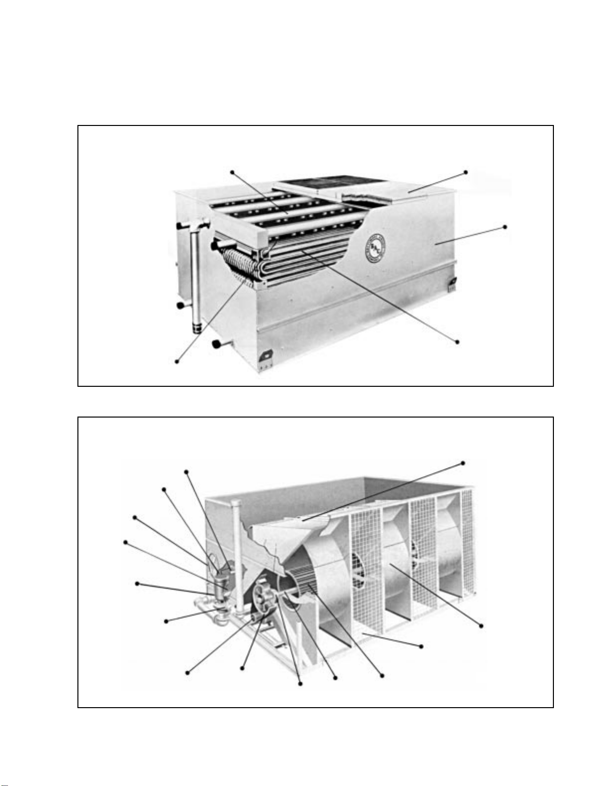
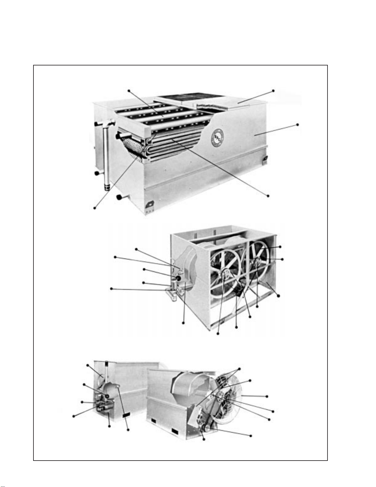
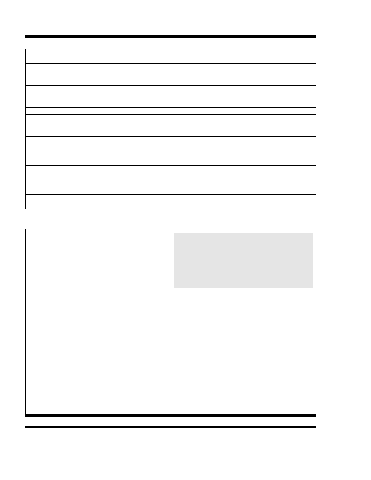
TABLE 1. Recommended Maintenance Services for Series V and Low Profile Series V Equipment.
TYPE SERVICE Start-Up Monthly Every Six
Months Shutdown Annually Ref. Page
Inspect General Condition of Unit
Clean Debris from Unit
Clean and Flush Basin
Clean Basin Strainer
Check and Adjust Basin Water Level
Inspect Heat Transfer Section
Inspect Spray Nozzles
Check and Adjust Fan Belt Tension
Check and Adjust Bleed Rate
Check Operation of Make-up Valve
Check Unit for Unusual Noise or Vibration
Check Fan Bearing Locking Collars
Check Motor Voltage and Current
Lubricate Fan Shaft Bearings
Lubricate Fan Motor Bearings
Lubricate Motor Base Adjusting Screw
Check Fan for Rotation Without Obstruction
Check Fan and Pump Motor for Proper Rotation
Drain Basin and Piping
Inspect Protective Finish
X
X
X
X
X
X
X
X
X
X
X
X
X
X
X
X
X
X
X
X
X
X
X
X
X
X
X
X
XX
X
X
X
X
X
X
X
X
XX
7
7
7
7
8
11
11
11
14
8
7
10
7
9
10
10
7
7
7
12
WARNING: Before performing any maintenance or inspection, make certain that all power has been
disconnected and locked in the off position.
WARRANTIES—Please refer to the Limitation of Warranties applicable to and in effect at the time of sale/purchase of these products.
FREEZE PROTECTION—These products must be protected by mechanical and operational methods against damage and/or reduced
effectiveness due to possible freeze-up. Please refer to the Cold Weather Operation guidelines (page 12) or contact the local B.A.C.
Representative for recommended protection alternatives.
SAFETY: The operation, maintenance, repair of this
equipment must be undertaken only by qualified per-
sonnel. All qualified personnel should be thoroughly
familiar with the equipment, the associated system and
controls, and the procedures set forth in this manual.
Proper care, procedures, and tools must be used in
handling, lifting, installing, operating, maintaining and
repairing this equipment to prevent personal injury
and/or property damage.
Lockout Warning:
For the protection of authorized ser-
vice and maintenance personnel, each fan and pump
motor associated with this equipment must be installed
with a lockable disconnect switch located within sight of
the cooling tower. No service work should be per-
formed on or near the fans, motors, and drives or inside
the unit without first ensuring the fan and pump motors
have been disconnected and locked out.
Electrical Hazard:
All electrical, mechanical, and rotat-
ing machinery constitute a potential hazard, particularly
for those not familiar with its design, construction, and
operation. Accordingly, adequate safeguards (including
the use of protective enclosures where necessary)
should be taken with this equipment both to safeguard
the public (including minors) from injury and to prevent
damage to the equipment, its associated system, and
the premises.
WARNING: PVC eliminators on this product are
not designed to support the weight of a person or
to be used as a storage or work surface for any
equipment or tools. Use of these PVC eliminators
as walking, working or storage surface may result
in injury to personnel or damage to equipment.
Units with PVC eliminators should not be covered
with a clear plastic tarpaulin.
Access:
Depending upon site conditions, it also may be
necessary to install bottom air inlet screens, ladders,
safety cages, stairways, access platforms, and handrails
and toeboards for the safety and convenience of autho-
rized service and maintenance personnel.
At no time should this equipment be operated
without all fan screens, access panels, and access
doors in place.
Caution:
The recirculating water system may contain
chemicals or biological contaminants, including Legionella,
which could be harmful if inhaled or ingested. Accordingly,
personnel who may be exposed directly to the discharge
airstream and the associated drift, mists generated during
operation of the water distribution system and/or fans, or
mists produced by high pressure water jets or compressed
air, should these be used to clean portions or components
of the recirculating water system, should wear respiratory
protection equipment approved for such use by OSHA
and/or local occupational safety and health authorities.

Operation
and Maintenance
7
INITIAL AND SEASONAL START-UP:
Prior to initial start-up or after a shut down period, the unit
should be thoroughly inspected and cleaned:
1. Cleanalldebris from inletair screens, fans,eliminators,
heat transfer sections, and the cold water basin.
2. Drain the cold water basin (with basin strainers in
place) and flush to remove accumulated dirt.
3. Remove, clean, and replace basin strainers.
4. Turn the fan(s) by hand to ensure rotation without
obstruction.
5. Check the locking collar on each fan bearing assem-
bly and tighten as required.
6. Check and, if necessary, adjust the fan belt tension.
7. Prior to seasonal start-up, lubricate the fan shaft and
motor bearings. The ball bearings are factory lubricat-
ed, but should be relubricated if the unit has been sit-
ting on site for more than a year before start-up.
8. Check float operated make-up valve to be sure it is
operating freely.
9. Fill the cold water basin with fresh water to the over-
flow level.
a. The initial biocide treatment should be applied at
initial start-up or before restart-up, where the basin
was completely drained. (see Water Treatment sec-
tion)
b. Following a shutdown period, where the basin was
not completely drained: it is recommended that
an initial shock treatment of appropriate bio-
cides be administered at restart-up to eliminate
accumulated biological contaminants.
10. Set the float on the make-up valve to shut off the valve
whenthefloat is approximately1/2” below theoverflow
level.
11. On Closed Circuit Cooling Towers and Evaporative
Condensers, start the pump and check for the proper
rotation as indicated by the arrow on the pump cover.
Oninstallationswhere the unitpump was notfurnished
by the factory, a globe valve should be installed in the
pump discharge line and the pump flow rate adjusted
to the correct water flow and pressure (2 psig at spray
headerconnection). Pressure greater than 10.0 psig
may cause damage to the distribution system.
12. Inspect the spray nozzles and heat transfer section.
13. Start the fan and check for the proper rotation as indi-
cated by the arrow on the fan housing.
14. Check the voltage and current of all three legs of the
fan and pump motors. The current should not
exceed the nameplate rating. After prolonged shut-
downs, the motor insulation should be checked with a
megger insulation tester prior to restarting the motor.
To prevent motor overload, do not operate fan
motor without design water flow over unit.
15. Check the bleed system to be sure it is fully function-
al and the bleed rate has been properly adjusted prior
to putting the unit into operation (see “Water
Treatment”).
AFTER 24 HOURS:
After24hours of operatingunder load, thefollowing services
should be performed:
1. Check the unit for any unusual noise or vibration.
2. Check the operating water level in the cold-water basin.
Adjust make-up float valve if necessary.
3. Readjust the fan belt tension.
4. Inspect the spray nozzles and heat transfer section.
OPERATION:
During operation, the unit should be inspected, cleaned,
andlubricatedon a regularbasis. The required servicesand
recommended frequency for each are summarized in Table
1 on page 6 of this bulletin.
SEASONAL SHUT-DOWN:
The following services should be performed whenever the
unit is to be shut-down for more than three days:
1. Drain the cold water basin and all piping that will be
exposed to freezing temperatures.
2. Clean and flush the cold water basin with the basin
strainersinplace. Leave the coldwater basin drainopen
so rain and melting snow will drain from the unit.
3. Clean the basin strainers and reinstall.
4. Lubricate the fan shaft and motor bearings, motor base,
and motor base adjusting screw.
5. Close the shut-off valve in make-up water line and drain
all exposed make-up water piping.
6. Inspect the protective finish on the unit. Clean and refin-
ish as required.
7. For VF1 and VFL closed circuit cooling towers,
follow the coil freeze protection guidelines explained on
page 13.

Maintenance
Procedures
8
COLD WATER BASIN
The cold water basin should be inspected regularly.Any
trash or debris which may have accumulated in the basin
or on the strainers should be removed.
Each month, the entire cold water basin should be
drained, cleaned, and flushed with fresh water to remove
the silt and sediment which normally collects in the basin
during operation. If not removed periodically, this sedi-
ment can become corrosive and cause deterioration
of the protective finish. When flushing the basin, the
strainers should be left in place to prevent the sediment
from re-entering the system. After the basin has been
flushed, the strainers should be removed, cleaned, and
replaced before refilling the basin with fresh water.
CAUTION: Do not use acid to clean the strainers.
The operating water level in the cold water basin will vary
somewhat with system thermal load (evaporation rate),
the bleed rate employed and the make-up water supply
pressure. Because the typical winter load is less than the
summer load, the winter evaporation rate is frequently
less than the summer evaporation rate. With this reduced
evaporation rate in winter, the water level in the cold water
basin will increase unless the float is re-adjusted. The
operating water level should be checked monthly and
the float re-adjusted as necessary to maintain the rec-
ommended operating level.
The water level in the basin of equipment designed for
remote sump operation is a function of the circulating
water flow rate, water outlet connection size, quantity and
location, and outlet piping size and configuration. The
remote sump unit is supplied without a water make-up
assembly and the sump operating level during remote
sump operation is not adjustable.
MAKE-UP VALVE
A float operated mechanical water make-up assembly is
furnished as standard equipment on all Series V and Low
Profile Series V equipment unless the unit has been
ordered with the optional electric water level control pack-
age or for remote sump application. It is located inside the
unit cold water basin within easy reach from the access
door at the connection end of each unit.
The standard make-up assembly (see Figure 1) consists
of a bronze make-up valve connected to a float arm
assembly and actuated by a large diameter polystyrene
filled plastic float. The float is mounted on an all-thread
rod which is held in place by wing nuts. The operating
water level in the cold water basin can be adjusted by
repositioning the float and all-thread rod using the wing
nuts provided.
The make-up assembly should be inspected monthly
and adjusted as necessary. The valve itself should be
inspected annually for leakage and the valve seat
replaced if necessary.
The make-up water supply pressure should be main-
tained between 15 and 50 psig for proper operation of
the valve.
To set the initial basin water level, adjust the wing nuts
so that the make-up valve is completely closed when the
water level in the cold water basin is 1/2” below the over-
flow connection. Under design thermal load and with aver-
age city water pressure (15 to 50 psig) at the valve, this
setting should produce the operating water levels stated
in Table 2. Note that if the thermal load is less than the
design load at the time of unit start-up, the procedure may
produce operating levels greater than that shown. It may
be necessary to re-adjust the float in order to attain the
recommended operating level. The unit basin should be
closely monitored and water level adjusted as necessary
during the first 24 hours of operation.
TABLE 2. Operating Water Level
Figure 1 – Water Make-Up Valve Assembly
Float Arm
Stop
Plastic U-Slip
Wing Nuts
Float Ball
Float Arm
Assembly
All Thread Rod
OPERATING
HEIGHT (measured
from basin bottom)
MODEL NO.
51/2
"
131/2
"
161/2
"
17
"
127/8
"
151/2
"
17
"
14
"
87/8
"
95/8
"
6
"
121/8
"
VTL, VFL, VCL
VF1-009 thru VF1-036, VC1-10 thru 135
VF1-048, VC1-150 thru 205
VF1-072, VC1-N208 thru N230
VTO-12 TO VTO-116
VTO-132 TO VTO-176
All VT1-N, VF1-096, VF1-144N,
VF1-192, VF1-288N, VC1-N243 thru
N470, VC1-C216 thru C469
All VT1, VTF1-144, VF1-216, VF1-288,
VF1-432, VC1-386 thru 1608
VC2-N138-N191
VC2-N206-N235
VC2-N261-N446
VC2-319-1774

Maintenance
Procedures
(continued)
9
As an option, an electric water level control package is
available in lieu of the above described mechanical make-
up assembly. The package consists of a probe-type liquid
level control assembly and a slow closing solenoid valve.
Stainless steel electrodes, factory set at predetermined
lengths, extend from a NEMA 4 electrode holder into the
cold water basin. These electrodes should be periodi-
cally wiped clean to prevent accumulations of scale,
corrosion, sludge or biological growth from interfer-
ing with the electrical circuit. With the electric water
level control package, the water level is maintained at the
recommended operating level regardless of the system
thermal load. Therefore, it is not necessary, nor is it rec-
ommended that the operating level be adjusted. During
initial and seasonal start-up, the probe-type level control
assembly should be bypassed to fill the cold water basin
to approximately 1/2” below the overflow connection.
Unit operation at the recommended water level will
ensure that the unit basin contains sufficient water volume
to prevent air entrainment in the circulating pump during
system start-up and to provide sufficient excess basin
capacity to accept the total system pull-down volume. The
“total system pull-down volume” is the quantity of water
suspended in the tower during pump operation plus that
contained in the water distribution system, external piping,
and any heat exchangers which could drain to the tower
cold water basin when the circulating pump is shut down.
FAN SHAFT BEARINGS
The fan shafts on VTO, VT1, VTL, VF1, VFL, VC1, and
VCL units are supported at each end by ball bearings (see
Figure 2), each equipped with a lubrication fitting and
locking collar. Models VTO-65 to 116, VF1-027, VF1-036,
and VC1-72 thru 135 also have a sleeve bearing (see
Figure 3) located midway on the shaft.
The fan shafts on VC2 units are supported by ball bear-
ings (see Figure 2A) in the middle of the shaft with fans at
each end. Each bearing is equipped with a lubrication fit-
ting and locking collar. Lubrication lines are extended to
the outside of the unit as standard.
Ball Bearings
Under normal operating conditions, the bearings should
be greased every 2,000 operating hours or at least every
six months. The bearings should also be greased at sea-
sonal start-up and shut-down. Only lubricate the bearings
with one of the following water resistant inhibited greases
which are good for ambient temperatures ranging from
–65°F to 250°F:
American – Rycon Premium #3
Exxon – Beacon #325
Shell – Aeroshell #7
Mobil – Mobilgrease #28
Chevron – SRI #3
Keystone – 84 EP Light
Only lubricate the bearings with a hand grease gun.
Do not use high pressure grease guns since they may
rupture the bearing seals. When lubricating, purge the
old grease from the bearing by gradually adding grease
until a bead of new grease appears at the seal.
Sleeve Bearings
Prior to start-up and during the first week of operation, the
bearing oil cup must be refilled with an industrial-type min-
eral oil (see Table 3) to saturate the felt wick in the bear-
ing reservoir. After the initial start-up, fill the bearing oil
cup every 1,000 operating hours or at least every six
months. When ambient temperatures below 0°F are
expected, a light oil must be used. With such light oils, the
bearing oil cup should be checked and refilled several
times during the first several hours of operation until the
bearings reach operating temperature.
LUBE
FITTING
LOCKING
COLLAR
Figure 2 – Ball Bearing
LUBE FITTING
LOCKING COLLAR
Figure 2A – Ball Bearing

Maintenance
Procedures
(continued)
10
CAUTION: Do not use oils containing detergents for
bearing lubrication. Detergent oils will remove the
graphite in the bearing sleeve and cause bearing fail-
ure. Also, do not disturb bearing alignment by tight-
ening bearing cap adjustment on a new unit as they
are torque adjusted at the factory.
FAN MOTOR BEARINGS
All Totally Enclosed Fan Cooled (TEFC) Fan Motors have
regreaseable bearings. The motor bearings should be
lubricated as recommended in the motor manufacturer’s
operating instructions that are attached to the motor when
the equipment ships from the factory.
LOCKING COLLARS
Each eccentric locking collar should be checked
every six months to ensure that the inner bearing
race is secured to the fan shaft. The locking collar can
be set using the following procedure (see Figure 4):
1. Loosen the set screw.
2. Using a drift pin or centerpunch, tap the collar (in the
hole provided) tangentially in the direction of rotation
while holding the shaft.
3. Retighten the set screw.
ADJUSTABLE MOTOR BASE:
The motor base slides and adjusting screw (See Figure 5)
should be coated twice a year using a good quality corro-
sion inhibiting grease such as one of those recommended
for lubricating the fan shaft bearings (see Page 9).
TEMP AMBIENT
70°F to 110°F
30°F to 70°F
5°F to 30°F
-25°F to 5°F
OIL CUP
Figure 3 – Sleeve Bearing
TABLE 3. Sleeve Bearing Lubricants
B.A.C. P/N TEXACO EXXON
#582628PI
#582627PI
Regal R & O 320
Regal R & O 150
Regal R & O 32
Capella 32
Teresstic 220
Teresstic 100
Teresstic 32
DRIFT
PIN (A) TAP THE LOCKING COLLAR
IN DIRECTION OF FAN ROTATION
(B) TIGHTEN SET SCREW
AFTER CAM IS LOCKED
DIRECTION
OF ROTATION
Figure 4 – Locking Collar Assembly
ADJUSTING
NUT
LOCK NUT
ADJUSTING SCREW
Figure 5 – Adjustable Motor Base
VTO, VT1, VTL, VF1, VFL, VC1, VCL
ADJUSTABLE MOTOR BASE:
The motor base hangers, hinges, and adjusting screw
(See Figure 5A and 5B) should be coated twice a year
using a good quality corrosion inhibiting grease such as
one of those recommended for lubricating the fan shaft
bearings (see Page 9).
MOTOR
BASE
HANGERS ADJUSTING
SCREW
Figure 5A – Adjustable Motor Base
VC2-N138-N446

FAN BELT ADJUSTMENT
Some of the smaller axial fan models use individual V-
belts, but most of the models use multi-groove, banded
belts. Belt tension should be checked and adjusted
(as needed) every month. To properly adjust the belt
tension, position the fan motor so that moderate pressure
on the belt midway between the sheaves will produce 1/2”
deflection in centrifugal fan units and the deflection shown
in Table 4 below for axial fan units. The position of the fan
motor can easily be changed by adjusting the rod which
extends from the frame to the motor base.
1. Loosen the locking nut (See Figure 5, 5a, 5b)
2. Rotate the adjusting nut
a. To loosen belt tension, turn clockwise (on models
VTL, VFL and VCL turn counterclockwise).
b. To tighten belt tension, turn counterclockwise (on
models VTL, VFL and VCL turn clockwise).
3 Tighten the locking nut – failure to do so may result in
the motor base vibrating free, hence, loosening the
belt tension.
Note: There should be no “chirp” or “squeal” when the fan
motor is started.
Figure 6 – Checking Sheave Alignment
HINGE
ADJUSTING
SCREW
Figure 5B – Adjustable Motor Base
VC2-319-1774
DEFLECTION
(inches)
MODEL NO.
VC2-N138-N191
VC2-N206-N235
VC2-N261-N301
VC2-N356-N446
VC2-319-1774
9/16
"
11/16
"
11/16
"
13/16
"
13/16
"
FAN DRIVES
The drive alignment should be checked annually to
ensure maximum belt life. This can be done by placing
a straightedge across both sheaves as shown in Figure 6.
When the drive is properly aligned, the straightedge will
contact all four points as indicated. If realignment is nec-
essary, loosen the motor sheave and align it with the fan
sheave. Allow approximately 1/4” for draw-up as the
motor sheave is pulled tight on the bushing, then retighten
the bushing screw:
FAN
SHEAVE
MOTOR
SHEAVE
POINT OF CONTACT
STRAIGHTEDGE
MOTOR REPLACEMENT
On rare occasions, the fan motor will have to be replaced.
On the VC2 models, make sure the drain holes are point-
ing in the downward direction. This may require that the
end bell be reversed on some motors.
SPRAY NOZZLES AND HEAT TRANSFER SECTION
The spray nozzles and heat transfer section should
be inspected and cleaned each month. The inspection
procedure is as follows:
1. Shut off the fan, but leave the pump running.
2. Remove the eliminators.
3. Check to see if the nozzles are producing the spray
pattern shown in Figure 7a for cooling towers or 7b for
coil products.
4. Clean any nozzles which are clogged. If necessary,
the nozzle and rubber grommet may be removed for
cleaning.
5. Inspect the coil or wet deck surface. Any corrosion,
damage, or obstructions must be corrected.
6. Some VF1, VFL, VC1, VC2, and VCL units are provid-
ed with an extended surface finned coil. During the win-
ter season, when the ambient temperature is well
below design, units with this coil can operate with the
spray pump off. The coil is designed for seasonal dry
operation followed by seasonal wet operation, and
not
for frequent cycling of the spray pump. Frequent spray
pump cycling may lead to excessive scale buildup.
Caution: Do not use steam or high pressure water to
clean cooling tower wet deck surface of materials
other than steel. 11
TABLE 4. Fan Belt Deflection for VC2 Models

Maintenance
Procedures
(continued)
12
SPRAY
NOZZLE
SPRAY
NOZZLE
360° UMBRELLA TYPE SPRAY
Figure 7a – Nozzle Spray Distribution (Cooling Towers)
Figure 7b – Nozzle Spray Distribution (Coil Products)
CORROSION PROTECTION
Series V units are constructed entirely of corrosion-resis-
tant materials. The wet deck surface and the eliminators
of the VT1, VTO and VTL are made of polyvinyl chloride
(PVC) which requires no protection against rot, decay,
rust, or biological attack. The standard coil of the VF1,
VFL, VC1, VC2, and VCL is constructed of all prime sur-
face steel, hot-dip galvanized after fabrication. The bal-
ance of the construction in all units is either heavy-gauge
galvanized steel, the optional BALTIBOND®Corrosion
Protection System, or Type 304 stainless steel.
Galvanized Steel Construction
The standard Series V and Low Profile Series V units are
constructed of hot-dip galvanized steel. These units
should be inspected annually.
Cold Weather
Operation
Inspect the inside of the unit for blemishes or corrosion on
the galvanized steel. Affected areas should be thoroughly
wire brushed and recoated with zinc-rich compound (ZRC).
BALTIBOND®Corrosion Protection System
The Series V and Low Profile Series V units can be con-
structed of hot-dip galvanized steel, protected with the
BALTIBOND®Corrosion Protection System as an option.
Scratches and scrapes on parts which do not require
extraordinary corrosion protection can be touched up with
a repair kit (B.A.C. Part No. 16-133P). In the unlikely
event that the damage is more extensive than simple
scratches or dents, contact your local B.A.C. Representative.
Series V and Low Profile Series V equipment can be oper-
ated in subfreezing ambient conditions provided proper
measures are taken:
1. Protection against basin water freezing when the unit
is idle.
2. Capacity control to prevent ice formation in heat trans-
fer sections during operation.
3. Protection against coil freezing (VF1 and VFL Closed
Circuit Cooling Towers and cooling circuits in VC1,
VC2, and VCL Evaporative Condensers.
Cold weather applications should be reviewed with the
B.A.C. Representative in your area to ensure that the unit
selection, location, control, and accessories are adequate
for reliable operation. Listed below are general guidelines,
which should be followed to minimize the possibility of
freeze-up.
PROTECTION AGAINST BASIN WATER FREEZING
When the unit is shut-down and exposed to subfreez-
ing ambient temperatures, the basin water may freeze.
A remote sump located in a heated indoor area is a desir-
able method of freeze protection. Alternatively, basin
heaters, electrical immersion heaters, steam coil, or hot
water coil) can be used to maintain the basin water at a
minimum temperature of 40°F. In addition to protect the
cold water basin, all exposed water piping including
pump piping below the overflow level and makeup
water lines should be traced with electrical heater tape
and insulated.

CAPACITY CONTROL
It is necessary to prevent the recirculating water from
approaching freezing conditions when the unit is
operating under load. Capacity control on centrifugal fan
units may be achieved through fan cycling, capacity con-
trol dampers, the ENERGY-MISER®Fan System, or two-
speed motors. Capacity control dampers offer the greatest
protection and should be used for close temperature con-
trol. Capacity control on axial fan units (VC2 only) may be
achieved by fan cycling or two-speed fan motors.
Warning:
Rapid on-off cycling can cause the fan
motor to overheat. It is recommended that controls be
set to allow a maximum of six-off cycles per hour.
Multiple fan motors serving a single coil, fill section, or fan
section must be cycled simultaneously. This applies to
models VT1-478 through VT1-600, VF1-216, VF1-432,
VC1-540 through 804, VC1-1158-1608, and VC2-319
through 1774.
Units with two-speed motors should have a 15-sec-
ond time delay during switch down from high to low
speed to avoid overloads on the low speed windings
of the motor. Units with the ENERGY-MISER®Fan
System should also have a 15-second time delay during
the switch down from high to low speed to avoid over-
loads on the lower horsepower motor.
Please note that capacity control dampers allow the
unit to operate longer and with closer control than the
ENERGY-MISER®Fan System, two-speed motor, and/or
fan cycling. The use of a modulating spray water by-
pass is
not
a recommended method of capacity control.
Variable Frequency Drives
Motors: Applications employing variable frequency drives
(VFDs) for fan motor control must use inverter duty elec-
tric motors built in compliance with NEMA Standard MG.1,
Part 31. The standard fan motors normally furnished
with B.A.C. products are not intended for this duty
and will not be warranted if so applied.
Warning:
When the fan speed of a Series V Closed
Circuit Cooling Tower or Evaporative Condenser is to
be changed from the factory set speed, including the
use of a variable speed control device, steps must be
taken to avoid operating at or near the fan’s “critical
speed” with resulting excessive vibration and stress-
es and the risk of personal injury and/or property
damage. Consult with your local B.A.C.
Representative on any application utilizing variable
speed control to determine whether any critical
speeds may be encountered and if any motor modifi-
cations may be required.
Recommended Operating Speeds: For optimum system
performance and equipment longevity, fan motors should
not be operated below 25% of full speed, nor within 10%
of any unit resonant frequencies. Contact your local
B.A.C. Representative for this information. 13
WARNING: Before performing any maintenance or
inspection, make certain all electric power has been
disconnected and locked in the off position.
Maximum Allowable Wire Runs: The VFD should be
located as close as possible to the inverter duty motor.
Depending on the style, operating voltage, and switching
frequency, the maximum recommended length of wire can
range from 20 to 200 feet. Consult the inverter manufac-
turer to determine the maximum allowable wire lengths for
your application.
PROTECTION AGAINST COIL FREEZING
(MODELS VF1 AND VFL ONLY)
The best protection against coil freeze-up is the use of
an antifreeze solution. An industrial grade inhibited ethyl-
ene glycol or propylene glycol solution is recommended
for most installations.
When an antifreeze solution is not possible, the system
must be operated to meet both of the following conditions.
1. Maintain the minimum recommended flow through the
coil at all times (see Table 5 below).
2. Maintain a heat load on the circulating fluid so that the
temperature of the fluid leaving the coil will not fall
below 50°F.
Minimum Coil Flow (GPM)Model No.
VF1-009, VF1-018,
VF1-027, VF1-036
VF1-048
VF1-072
VF1-096, VF1-144N
VF1-144, VF1-216N
VF1-192, VF1-288N
VF1-288, VF1-432
VFL-012 thru VFL-048
VFL-072 thru VFL-096
50
75
100
125
200
250
400
65
125
TABLE 5. VF1 and VFL Minimum Coil Flow Requirements
If the process load is extremely light or shut off, it may be nec-
essary to apply an auxiliary heat load to the circulating fluid
to maintain the fluid at 50°F when freezing conditions exist.*
Draining the coil is not recommended as a normal
method of freeze protection. Frequent draining pro-
motes corrosion inside the coil tube. However, draining is
acceptable as an emergency method of freeze protection
if the coil is not protected by an antifreeze solution. The
local B.A.C. Representative should be consulted for
guidelines on the installation of an emergency coil drain
system.
*For evaporative chilling applications only, the leaving fluid temper-
ature can be maintained as low as 45°F with glycol solutions.
Consult the local B.A.C. Representative for necessary precaution.

Recirculated Water Quality Guidelines
can be adjusted using the valve in the bleed line and
measured by filling a container of known volume while
noting the time period. The bleed rate and water quality
should be periodically checked to ensure that ade-
quate control of the water quality is being maintained.
The required continuous bleed rate may be calculated by
the formula, Evaporation Rate
Bleed Rate = Number of Cycles of Concentration – 1
The evaporation rate can be determined by one of the
following:
1. The evaporation rate is approximately 2 GPM per 1
million BTU/HR of heat rejection.
2. The evaporation rate is approximately 3 GPM per 100
tons of refrigeration.
3. Evaporation Rate = Water Flow Rate x Range x .001
Example: At a flow rate of 900 GPM and a cooling range
of 10°F, the evaporation rate is 9 GPM (900 GPM x 10°F
x .001 = 9 GPM).
Note: For Closed Circuit Cooling Towers, the flow rate to
be used in this calculation is the flow through the coil.
Note: The bleed line must be furnished by others on VTO,
VT1 and VTL cooling tower models.
If the site conditions are such that constant bleed-off
will not control scale or corrosion and maintain the
water quality within the guidelines, chemical treat-
ment may be necessary. If a chemical treatment pro-
gram is used, it must meet the following requirements:
1. The chemicals must be compatible with the unit con-
struction (zinc-coated) steel as well as all other mate-
rials used in the system (pipe, heat exchanger, etc.)
2. Chemicals to inhibit scale and corrosion should be
added to the re-circulating water by an automatic
feed system on a continuously metered basis. This
will prevent localized high concentrations of chemicals,
which may cause corrosion. It is recommended the
chemicals be fed into the system at the discharge of
the recirculating pump on open cooling loops. They
must
not
be batch fed directly into the cold water
basin. For Series V coil products, chemicals should
be metered into the recirculating water over the coil.
3. Acid water treatment is
not
recommended unless
the unit(s) have been furnished with the BALTI-
BOND®Corrosion Protection System or is con-
structed of Type 304 stainless steel - in which cases
acid treatment can be used provided the requirements
of paragraph 1 and 2 above are maintained.
SYSTEM CLEANING
Closed Circuit Cooling Towers
With proper precautions, alkaline solution used to clean
condenser water systems prior to start-up may be circulat-
ed through a Series V or Low Profile Series V Closed
Circuit Cooling Tower.
Water
Treatment
CORROSION AND SCALE CONTROL
In Evaporative Cooling Products, cooling is accomplished
by the evaporation of a portion of the process water as it
flows through the unit.As this water evaporates, the impuri-
ties originally present remain in the recirculating water. The
concentration of the dissolved solids increases rapidly and
can reach unacceptable levels. In addition, airborne impuri-
ties are often introduced into the recirculating water, intensi-
fying the problem. If these impurities and contaminants are
not effectively controlled, they can cause scaling, corrosion,
and sludge accumulations which reduce heat transfer effi-
ciency and increase system operating costs.
The degree to which dissolved solids and other impuri-
ties build up in the re-circulating water may be defined as
the cycles of concentration. Specifically, cycles of concen-
tration is the ratio of dissolved solids (for example – total
dissolved solids (TDS), chlorides, and sulfates) in the re-
circulating water to dissolved solids in the make-up water.
For optimal heat transfer efficiency and maximum
equipment life, the cycles of concentration should be
controlled such that the re-circulating water is main-
tained within the guidelines list below.
14
Galvanized
Steel
BALTIBOND®
Corrosion
Protection System*
pH
Hardness as CaCO3
Alkalinity as CaCO3
Total Dissolved Solids
Chlorides
6.5 to 9.0
30 to 500 ppm
500 ppm max.
1200 ppm max.
250 ppm max.
7.0 to 9.0†
30 to 500 ppm
500 ppm max.
1000 ppm max.
125 ppm max.
† Units having galvanized steel construction and a circu-
lating water pH of 8.3 or higher will require periodic pas-
sivization of the galvanized steel to prevent “white rust,”
the accumulation of white, waxy, non-protective zinc cor-
rosion products on galvanized steel surfaces.
* Closed Circuit Cooling Towers and Evaporative
Condensers with BALTIBOND®Corrosion Protection
System and hot-dip galvanized coils must use the water
quality guidelines for galvanized steel units.
In order to control the cycles of concentration such that
the above guidelines are maintained, it will be necessary
to “bleed” or “blowdown” a small amount of recirculating
water from the system. This “bleed” water is replenished
with fresh make-up water, thereby limiting the build-up of
impurities.
Typically the bleed is accomplished automatically
through a solenoid valve controlled by a conductivity
meter. The conductivity meter set point is the water
conductivity at the desired cycles of concentration
and should be determined by a competent water
treatment expert. (Note: The solenoid valve and conduc-
tivity meter must be supplied by others.) Alternatively, a
bleed line with a valve can be used to continuously bleed
from the system. In this arrangement, the rate of bleed

Baltimore Aircoil Company maintains a stock of replace-
ment parts at each of its manufacturing facilities.
Shipment of these parts is normally within four days after
receipt of an order. In emergency situations, shipment can
usually be made within twenty-four hours. To order factory
authorized parts, contact your local B.A.C.
Representative. Be sure to include the unit serial number
when ordering any parts.
To facilitate servicing the unit, it is suggested that the fol-
lowing parts be carried on hand:
Make-Up Float Ball
Valve Seat for Make-Up Valve
Fan Shaft Bearings
Fan Wheel
Fan Belt(s)
Fan Shaft
Spray Nozzles and Grommets
Spray Distribution Branch Grommet
Access Door Gasket
The necessary precautions include:
1. Limit the duration of the cleaning to one, or at the
most, two days.
2. The temperature of the solution should never exceed
100°F.
3. The maximum concentration of chemicals in the circu-
lation solution should not exceed any of the following:
5% Sodium Hydroxide
5% Sodium Metasilicate
2% Sodium Carbonate
2% Tetra Sodium Pyrophosphate
0.5% Trisodium Phosphate
0.5% Sodium Nitrate
5-10% Butyl Cellosolve
Evaporative Condensers
The installation and manufacturing processes commonly
used for field-assembled steel-piped refrigeration systems
leave weld byproducts inside coils and connecting piping.
It is common practice to install filters and/or strainers that
remove contaminants during initial system operation.
Shortly after system startup, the filters and/or strainers
should be cleaned or replaced.
Biological Control
Bleed-off with or without chemical treatment for
scale and corrosion control is not adequate for
control of biological contamination. The growth
of algae, slimes and other microorganisms, if unchecked,
will reduce system efficiency and may contribute to the
growth of potentially harmful microorganisms, including
Legionella, in the recirculating water system.
Accordingly, a biocide treatment program specifically
designed to address biological control should be initi-
ated when the system is first filled with water and
administered on a regular basis thereafter in accor-
dance with the supplier’s instructions. Liquid biocides
may be added to the basin of the cooling unit in dilute
form. If a solid form of biocide is used, it should be added
to the system via a pot feeder. If ozone water treatment
is used, ozone concentrations should not exceed 3-4
ppm in order to ensure maximum equipment life.
B.A.C. offers a simple, easily applied, low maintenance
form of biological control, the IOBIO‚Bacteria, Slime and
Algae Control. The control is easy to use and requires lit-
tle maintenance. By delivering low concentrations of
iodine through the make-up water line, the IOBIO‚Control
automatically controls unwanted microbiological contami-
nants in the open water system. Contact your local B.A.C.
Representative for more information.
START-UP FOLLOWING A SHUT-DOWN PERIOD
To minimize the risk from biological contamination
following a shut-down period, it is recommended that
the entire system (evaporative cooling equipment,
system piping, heat exchangers, etc.) be drained
when the system is to be shut-down for more than
three days. To resume operation of a drained system,
clean all debris, such as leaves and dirt from the cooling
tower and re-fill the system with fresh water. While operat-
ing the circulating pump(s) and prior to operating the unit
fans, execute one of the following two alternative biocide
treatment programs:
1. Resume treatment with the biocide, which had been
used prior to shut-down. Maintain the maximum recom- 15
Factory
Authorized Parts
mended biocide residual (for the specific biocide) for a
sufficient period of time (residual and time will vary with
the biocide) as recommended by the water treatment
supplier to bring the system under good biological con-
trol.
2. Check the pH of the circulating water and, if necessary,
adjust it to 7.0 to 7.6. Then treat the system with sodi-
um hypochlorite to maintain a level of 4 to 5 mg/l (ppm)
free chlorine (as Cl2) over a six (6) hour period. Test
kits that can be used to measure the free residual of
chlorine are commercially available.
When it is not practical to drain the system during shut-
down periods, a by-pass line with shut-off valves should
be installed to permit the cooling water to be circulated
throughout the system, including the unit basin, while by-
passing the heat transfer section. Then, after each shut-
down of three (3) days or more, the system should be
treated prior to restarting the unit using one of the two
methods described above.
However, while circulating the treated cooling tower
water through the entire system, the cooling tower fill
should be by-passed and the tower fans kept inopera-
tive. After the biocide residual has been maintained at the
required level for at least six (6) hours, the water can be
directed over the fill and the tower returned to service.
The standard water treatment program (including the bio-
logical treatment) should be resumed at this time.
For specific recommendations on treatment for scale,
corrosion, or biological control, consult a qualified
water treatment consultant.
COIL CLEANING
Both the inside and outside of the heat exchange coil may
require occasional cleaning. The chemicals used must be
compatible with the materials being treated (for example -
standard coil: outside of the coil is galvanized steel; inside
coil is black carbon steel). For specific recommenda-
tions on coil cleaning, consult a qualified water treat-
ment consultant.

Baltimore Aircoil
P.O. Box 7322, Baltimore, Maryland 21227
410-799-6200 Fax 410-799-6416
www.BaltimoreAircoil.com
email: [email protected]
SEN-10M-09/00
Printed on Recycled Paper
Printed in the U.S.A.
®
This manual suits for next models
9
Table of contents
Other Baltimore Aircoil Company Cooling Box manuals