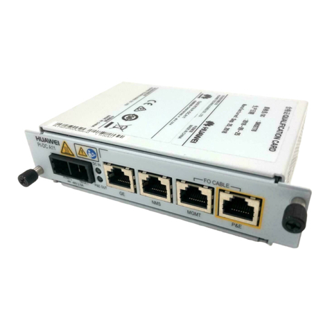
Huawei OptiX RTN PI-DC B20 Installation guide

OptiX RTN PI-DC B20
Product Overview and Installation Guide
Issue: 07
Date: 2018-10-30
Huawei Technologies Co., Ltd.
Address: Huawei Industrial Base
Bantian, Longgang
Shenzhen 518129
People's Republic of China
Website: http://www.huawei.com
Email: support@huawei.com
No part of this document may be reproduced or transmitted in any form or by any means without prior
written consent of Huawei Technologies Co., Ltd.
Copyright © Huawei Technologies Co., Ltd. 2018. All rights reserved.
01
Safety Precautions
•Customer equipment connected to the GE electrical ports of outdoor PIs must have surge protection
capabilities. If customer equipment does not have surge protection capabilities, PIs must be installed indoors.
•Do not touch the connector terminals or pins of P&E cables or DC power cables. Instead, hold the insulation
parts of the cables.
•Prevent conductors or hands from touching the terminals or pins in the P&E ports and DC input/output ports on
PIs.
•Before installing a DC input power cable on a PI, identify the positive and negative ends of the cable. Ensure
that the cable is connected correctly. Install a circuit breaker at the negative end of the external power supply
device to prevent circuit loops from damaging the power cable and PI.
•Before installing a DC output power cable on a PI, identify the positive and negative ends of the cable. Ensure
that the cable is connected correctly. Do not connect the output port of the external power supply device to the
DC output port of the PI.
•Do not connect the output port of the external power supply device to a P&E port of the PI.
•Do not install any cables when devices are powered on.
•When making and installing cables, avoid dropping any metal scraps or other miscellaneous objects into a PI.
•After setting DIP switches, switch off the power supply. After waiting for 6 seconds, switch on the power supply
again.
HUAWEI TECHNOLOGIES CO., LTD .

AAppearance and Ports
The RTN PI-DC B20 is a full-outdoor PI with high power. It uses DC power input and transmits GE electrical signals and -48 V power signals to the full-outdoor RTN 300 equipment through an
outdoor network cable.
Product Overview
CIndicator Status Description
Indicator Status Meaning
POWER Steady green Power is being supplied.
Off No power is supplied.
DC OUT Steady green The PI uses DC power output,
and the output is normal.
Off The DC output port does not
output any power.
P&E OUT
Steady green The PI uses P&E output, and the
output is normal.
Blinks green In PSE-PD mode, the PI is in the
handshake state.
Off
The P&E port does not output any
power.
BPort Description
The pin assignments for Ethernet service signals in the ports GE1 and GE2 are consistent with those in
the ports P&E1 and P&E2. These ports all support the MDI, MDI-X, and auto-MDI/MDI-X modes.
The P&E1 OUT and P&E2 OUT indicators inside a PI indicate the output status of the corresponding
ports. Their meanings are the same as the meaning of the P&E OUT indicator on the side of the PI.
Pin Description
1 BGND
2 BGND
3 -48 V power signal
4 BGND
5 BGND
6 -48 V power signal
7 -48 V power signal
8 -48 V power signal
Whether the P&E ports use MDI or MDI-X mode to transmit Ethernet service signals does not affect the
pin assignments for power signals.
Pin assignments for power signals in the P&E ports
Maintenance
compartment
opened
Power cable
stripping indicator
Port
area
P&E port
indicators
DIP switches for
setting the power
output mode
DIP switches for
setting the number
of P&E outputs
DC input port DIP switches for
setting the P&E
mode
P&E ports
GE ports
02
DC output port
Side view
PGND ground point

Principles and Application Scenarios
Product Overview
The RTN PI-DC B20 receives one channel of DC power signals and two channels of GE service signals.
After the PI receives DC power signals, the DC-DC processing module increases the voltage to -51.0 V.
If DC output is required, set the corresponding DIP switch to select the DC output mode. Then, the PI outputs the DC power
signals with the voltage increased to the DC output port.
If P&E output is required, set the corresponding DIP switch to select the P&E output mode. Then, the signal coupling module
couples DC power signals and GE service signals into P&E signals and outputs the P&E signals to the P&E port.
The frequencies of DC power signals and GE service signals do not interfere with each other. Therefore, the two types of
signals can be transmitted over the same twisted pair.
DC-DC
processing
mode
DC IN DC OUT
Signal
coupling
module
GE1 P&E1
Signal
coupling
module
GE2 P&E2
DC-PI working principles
DC-PI
UNI-
side
device
powered
device
powered
device
UNI-
side
device
≤ 100 m
•The PI only couples GE signals and power signals, but does not regenerate or strengthen GE signals. Therefore, the
network cable between the UNI-side device and the powered device must not be longer than 100 m.
•The maximum distance between the PI and the powered device varies depending on the power of the powered device.
For details, see technical specifications.
powered
device
Maximum
distance between
the PI and
powered device
Maximum
distance between
the PI and
powered device
CAUTION
BApplication Scenarios
APrinciples
The RTN PI-DC B20 can supply power to OptiX RTN 300 full-outdoor microwave equipment series. The power supply
mode of the PI varies according to powered device type.
Mapping between powered device types and power supply modes
03
Device Type Version PI Support
(Yes/No) Power Supply Mode
RTN 310 (Integrated)
SHXA2 board
Yes Turn the DIP switch to the Force mode.
SXA3 board
Yes
1. Turn the DIP switch to the P&E1 and P&E2 Out mode.
2.
Turn the DIP switch to the PSE-PD mode.
RTN 310
(Split) Yes
1. Turn the DIP switch to the P&E1 and P&E2 Out mode.
2. Turn the DIP switch to the PSE
-PD mode.
RTN 320 (Integrated)
Yes
1. Turn the DIP switch to the P&E1 Out Only mode (only
supports P&E1 port power supply).
2. Turn the DIP switch to the Force mode.
RTN 320 (Split)
No Support for DC output only
RTN 320F
Yes Support for DC output only
RTN 360 (V
-band) Yes
1. Turn the DIP switch to the P&E1 and P&E2 Out mode.
2. Turn the DIP switch to the PSE
-PD mode.
RTN 380 (E
-band)
SHUF3 board
Yes Turn the DIP switch to the Force mode.
MXUF4 board
Yes
1. Turn the DIP switch to the P&E1 and P&E2 Out mode.
2. Turn the DIP switch to the PSE
-PD mode.
RTN 380e
Yes
1. Turn the DIP switch to the P&E1 and P&E2 Out mode.
2. Turn the DIP switch to the PSE
-PD mode.
RTN 380A
Yes
1. Turn the DIP switch to the P&E1 and P&E2 Out mode.
2. Turn the DIP switch to the PSE
-PD mode.
RTN 380AX
Yes
1. Turn the DIP switch to the P&E1 Out Only mode (only
supports P&E1 port power supply).
2. Turn the DIP switch to the Force mode.
RTN 380H
MXUI5 board
Yes
1. Turn the DIP switch to the P&E1 Out Only mode (only
supports P&E1 port power supply).
2. Turn the DIP switch to the Force mode.
MXXI5 board
Yes
1. Turn the DIP switch to the P&E1 Out Only mode (only
supports P&E1 port power supply).
2. Turn the DIP switch to the Force mode.

Technical Specifications
Product Overview
APower Supply
Item Description
Input voltage DC input, with the voltage ranging from –38.4 V to –57.6 V
Input power cable diameter 2.5 mm2
Output voltage mode Set through DIP switches:
•DC output
•P&E output
Output voltage -51.0 V
DC output
mode
Number of power
output channels 1
Output power DC output power ≤153 W
Distance between the
PI and powered
device
Shorter than or equal to 300 m when 2.5 mm2cables are used and
load power consumption is 105 W or less or when 4 mm2cables
are used and load power consumption is 126 W or less
P&E output
mode
Number of power
output channels Set through DIP switches:
•1
•2
P&E mode Set through DIP switches:
•PSE-PD mode
•Force mode
Output power •P&E (one channel) output power ≤150 W
•P&E (two channels) output power of each channel ≤75 W
Distance between the
PI and powered
device
Shorter than or equal to 100 m when there is one output channel
and load power consumption is 100 W or less or when there are
two output channels and the load power consumption of each
channel is 62 W or less
Item Description
Electromagnetic compatibility
•Passes CE certification.
•Complies with EN55022 Class B.
•Complies with IEC61000-4-4.
•Complies with IEC61000-4-6.
Safety
•Passes CE certification.
•Complies with EN60950-22.
•Complies with EN60950-1.
•Complies with IEC60950-22.
•Complies with IEC60950-1.
Item Description
Major reference standards
Operation Complies with EN 300 019-1-4 (Class
4.1).
Transportation Complies with EN 300 019-1-2 (Class
2.3).
Storage Complies with EN 300 019-1-1 (Class
1.2).
Operating temperature -33°C to 55°C (wind speed: 0.5 m/s)
Relative humidity 5% to 100%
Earthquake resistance •Complies with GR-63-CORE Zone4.
•Complies with YD5083.
•Complies with ETS EN300019-1-4[1].
Protection class IP65
Item Description
Dimensions (H x W x D) 250 mm x 180 mm x 52 mm
Weight 3 kg
BDimensions and Weight
CElectromagnetic Compatibility and Safety Compliance
DDeployment Environment
04

Terminating a DC Output Power Cable with a Connector
10/11 >>
Strip a power cable based on the stripping
indicator.
1Use a screwdriver to poke the cable locking
latches out.
2
05
For the stripping length, see the stripping indicator on the PI.
NOTE
Installation Guide
Push the cable locking latches on both sides
back. Slightly pull the cable to check whether
it is connected securely.
If the wires slide outward or are exposed outside the
holes, remove the cable and cut the wires. Then strip
and connect the cable again.
A line must be inserted in the center of a hole.
A line must be perpendicular to a hole.
A line must be inserted in the
center of a hole.
4
CAUTION
Insert the power cable.
Hole 2 (-): Insert a blue -48 V line into it.
Hole 1 (+): Insert a brown (black) 0 V
ground line into it.
Ensure that the positive and negative lines are correctly connected.
Red cable
locking latch
Blue cable
locking latch
3
Avoid dropping any miscellaneous objects (especially
metal scraps) in the maintenance compartment. Clean
up them immediately if any.
CAUTION
12 mm 10 mm 10 mm

Terminating a Ground Cable with an OT Terminal
Strip a ground cable.
A: OT terminal
B: ground cable
C: exposed cable conductor
L1: length of the exposed cable
When you are skillful, you can determine L1
based on the length of the OT terminal lug.
When striping off the insulation layer of the
ground cable, take care not to damage or nick
the metal conductor of the cable.
Fit the exposed cable into the
OT terminal.
Ensure that the cable conductor does not
protrude more than 2 mm (L2) from the OT
terminal.
Crimp the OT terminal lug.
The impression left from crimping the lug may
differ depending on the crimping tool used.
Mapping between the cross-sectional area of a cable
conductor (C) and the length of an exposed cable (L1)
Cross-sectional
area of C (mm2) L1 (mm)
1
1.5
2.5
4
7
7
7
8Crimp the OT
terminal lug.
NOTE
CAUTION
CAUTION NOTE
06
123
Installation Guide

Terminating a DC Input Power Cable with a Connector
Stripping a Power Cable
A
Use a pair of diagonal pliers to trim off the -48 V power line.
8 mm
Cable core
Strip the 0 V ground line in the same way.
8 mm
Cable core
For the stripping length, see the stripping
indicator on the PI.
NOTE
1
2 3
07
Installation Guide
Installing Cord End Terminals
B
12 mm 10 mm 8 mm
Strip a power cable based on the stripping indicator.
1Install cord end terminals onto the cable cores. 2
After crimping a cord end terminal, check whether the cable core is exposed
outside the terminal. If the cable core is exposed, recrimp the terminal.
After the power switch is turned on, sparks may be generated at exposed cable
cores when an inappropriate operation is performed.
CAUTION
Crimp all cord
end terminals.

Terminating a DC Input Power Cable with a Connector
Connecting the Power Cable to the Connector
C
Insert the blue power line of the cable into a power cable
connector.
Power Cable Connector Terminal Line
--48 V power line (blue)
+0 V ground line (brown/black)
Fasten the line. Pull the line slightly. If the line is loose, fasten it again.
After fastening a line, check whether the cable core is exposed outside the connector terminal. If the cable core is
exposed, strip the cable again.
After the power switch is turned on, sparks may be generated at exposed cable cores when an inappropriate
operation is performed.
CAUTION
Pull the line slightly.
Repeat steps 1-3 to connect the ground line to the connector.
All the lines are fastened, and no
cable core is exposed outside the
connector.
1
23
4
08
Installation Guide

Terminating an Outdoor Network Cable with Shielded RJ45 Connectors
16/17 >>
Prepare the following tools.
RJ45 connector crimping tool
Diagonal pliers
Prepare an outdoor network cable
and shielded RJ45 connectors.
1. Core wire
2. Aluminum foil
3. Braid shield
4. Outer jacket
5. Shielded RJ45 connector
Strip the cable.
Length of the stripped
cable: 20 mm Strip off the braid shield and cut
the aluminum foil and unwanted
materials.
When stripping off the outer jacket, take care not to damage the braid shield
or aluminum foil.
Remove the outer jacket.
Arrange the core wires according to the pin assignments and cut them
neatly (exposing a length of 12 mm).
12 mm
Cut the core wires neatly.
Length of each exposed core wire: 12 mm
8: brown
7: white and brown
6: green
5: white and blue
4: blue
3: white and green
2: orange
1: white and orange
Insert the arranged core wires into an RJ45 connector according to the pin
assignments and crimp the connector with the crimping tool.
Pin assignments of an RJ45 connector
Crimp the RJ45
connector.
Cut off the exposed braid shield and materials
along the edge of the connector.
Cut off the exposed braid
shield and materials.
Outdoor network cable
Terminate a connector on the other end of the network cable, and then test the cable
for continuity using a network cable tester.
Optional: Use a multimeter to measure the impedance of core wires. The impedance
difference between core wires must be less than 5%.
8
•Before crimping, ensure that the core wires are fully inserted in the RJ45
connector.
•Use the crimping tool to crimp the connector with force.
•After crimping, verify that the connector has been crimped tightly.
09

Open the cover of the PI.
Loosen the screws on the cover of the PI to open
the cover.
Remove waterproof blocks from the cable
holes through which cables will be routed.
1
1
2
10
2Set DIP switches according to the plan.
Install a ground cable.
3
Connect the OT terminal of the ground
cable to the ground screw.
After installing the ground cable, apply rust inhibitor to the ground
point and around the ground screw.
CAUTION
Ground cable
Ground clip base.
Before the installation, scratch off the antirust paint and oxide layer
on the ground point. After finishing the installation, treat the ground
point with antirust and waterproof materials.
Installation Guide
Installing a PI
1The PI is used for DC power
supply onsite.
2The P&E1 port of the PI is used
for power over ethernet supply
onsite.
3Both the P&E1 and P&E2 port
of the PI is used for power over
ethernet supply onsite.
If DC OUT mode will be used, turn DIP
switch 1 for setting the power output
mode upwards.
If PSE-PD mode will
be used, turn DIP
switch 1 for setting
the power over
ethernet mode
downwards.
If force mode will be
used, turn DIP switch
1 for setting the
power over ethernet
mode upwards.
If PSE-PD mode will
be used, turn DIP
switches 1 and 2 for
setting the power
over ethernet mode
downwards.
If force mode will be
used, turn DIP switches
1 and 2 for setting the
power over ethernet
mode upwards.
Waterproof blocks
If P&E OUT mode
will be used, turn DIP
switch 1 for setting
the power output
mode downwards.
If P&E1 OUT only
mode will be used,
turn DIP switch 2 for
setting the number of
P&E outputs
upwards.
Turn DIP switch 1 for
setting the power
output mode
downwards.
Turn DIP switch 2 for
setting the number of
P&E outputs
downwards.
NOTE
In normal conditions, you must first select the power supply mode and then power on. If you
need to change the power supply mode after power-on, you need to restart the PI.

CAUTION
Install an output power cable on the PI.
4
Install an input power cable on the PI.
3
Before installing a DC input power cable, identify the positive and negative ends of the
cable. Ensure that the cable is connected correctly. Install a circuit breaker at the negative
end of the external power supply device to prevent circuit loops from damaging the power
cable and PI.
Connect the DC power connector to
the DC power ports.
Install a wire clip over the
shield layer of the DC power
cable.
1
2
Power supply
device
Connected to an RTN 300
(+)(-)
11
Installation Guide
Installing a PI
Connect the DC power connector to
the DC power ports.
Install a wire clip over the
shield layer of the DC power
cable.
1
2
CAUTION
Before installing a DC output power cable, identify the positive and negative ends of the
cable. Ensure that the cable is connected correctly.
Avoid dropping any metal scraps or other miscellaneous
objects on the front panel or in any ports of the PI.
CAUTION
Avoid dropping any metal scraps or other
miscellaneous objects on the front panel or
in any ports of the PI.
CAUTION

You can lay out a cable and then strip it at the wire clip.
When you strip a cable using this method, pay attention to the following points:
1. Ensure that the cable has been connected to the corresponding PI port and laid out in
the cable trough before you strip the cable. Ensure that the stripping length matches
the wire clip size. (See the preceding CAUTION.)
Connected to the peer GE device
Install PI service cables to the ports GE1/P&E1/GE2/P&E2.
CAUTION
Tips
Wire clip
The shield layer
is not exposed.
The exposed shield layer is
so long that it extends to the
waterproof cable trough.
The shield layer is
not fastened using
a wire clip.
Shield layer
Strip off the shield layer of a cable according
to the stripping indicator.
Loosen the corresponding wire clip on the PI.
Route the cable through the rubber ring on
the waterproof cable trough and the wire clip.
Tighten the wire clip and ensure that the wire
clip is completely pressed against the shield
layer with no contact of the sheath.
1
2
3
4
The shield layers of all cables connected to the PI must be grounded using wire clips.
Otherwise, the cables may be damaged by lightning strikes.
CAUTION
Avoid dropping any metal scraps or other miscellaneous
objects on the front panel or in any ports of the PI.
CAUTION
5
Connected to an RTN 300
Connected to the peer GE device
Connected to an RTN 300
2. Avoid dropping any metal scraps or other miscellaneous objects on the front panel or in any ports
of the PI.
12
Installation Guide
Installing a PI
When mapping RTN 320/380H, only the
GE1 and P&E1 interfaces are used to
transmit service and power supply.
NOTE

Close the cover of the PI and tighten all the screws on the cover.
•Tighten the screws in sequence, as shown in the
following figure.
•Tighten all the screws on the cover (2.8±0.28 N·m).
NOTE
Mark the
positions to
drill holes.
Hole with Ф8 and a depth from
52 mm to 60 mm
Determine the positions for mounting the PI on the wall, drill holes, and install bolts. If multiple PIs need to be
mounted, reserve at lease 50 mm of space around each PI for ventilation.
Down
(Optional) Mount the PI onto a wall.
67
Drill holes for mounting the PI.
1
Mount the PI onto the wall.
2
CAUTION
•Before fastening the PI onto the wall, hole the PI to prevent it
from falling down.
•Before fastening the PI, ensure that its service cable holes all
face downwards.
13
Holes for
mounting
onto a wall
Holes for
mounting
onto a wall
Installation Guide
Installing a PI
Small flat
washer
Big flat
washer
Nut
1
2
3
4
5

(Optional) Mount the PI onto a pole or tower.
8
Mounting
holes for
hose
clamps
Route hose clamps through mounting holes and fasten the hose clamps on the pole or tower.
1
Fasten the
hose clamps.
2
CAUTION
•Before fastening the PI onto the pole or tower, hole the PI to
prevent it from falling down.
•Before fastening the PI, ensure that its service cable holes all
face downwards.
14
Installation Guide
Installing a PI
Install the PI on the support.
Down

10/11 >> 15
NOTE
Connection between PI and RTN 300
RTN 320/380H
When the RTN 320/380H is installed at a high position on a tower,
maintenance personnel cannot performance off-tower
maintenance through WLAN. It is recommended to add an
outdoor network cable to connect the P&E2 interface of the PI.
The network element can be accessed by linking the notebook to
the GE2 interface for maintenance.
For the RTN 320/380H, a network management cable can be
connected to the NMS/GE multifunctional port. Note that network
management cables cannot be connected to both the NMS/GE
multifunctional port and the independent NMS port.
When a PI is used for P&E power supply for RTN
320/380H, the correct DIP switch:
P&E1GE1
Web LCT
NOTE
When the RTN 380 is installed at a high position on a tower,
maintenance personnel cannot performance off-tower
maintenance through WLAN. It is recommended to add an
outdoor network cable to connect the P&E1 or P&E2 interface
of the PI. The network element can be accessed by linking the
notebook to the GE1 or GE2 interface for maintenance.
For the RTN 380 (V100R002 or later), a network management
cable can be connected to the GE(e) port. In this case, you
need to use the NMS to configure the GE(e) port connected to
the Web LCT as an NMS port, or configure the network adapter
of the laptop so that the laptop can receive and transmit IP
packets carrying DCN VLAN IDs.
When a PI is used for P&E power supply for RTN 380, the
correct DIP switch:
Connect to P&E Interface
Connect to NMS interface
P&E2GE2
Access GE
service
RTN 380
P&E1GE1
Web LCT
P&E2GE2
Network management cable Network management cable
Access GE
service
Connect to P&E Interface
Connect to NMS interface
CAUTION
•Turn DIP switch 2
for setting the
number of P&E
outputs upwards
(P&E1 OUT mode).
•Turn DIP switch 1
for setting the
power output mode
downwards (P&E
OUT mode).
•Turn DIP switch 1
for setting the
power output mode
downwards (P&E
OUT mode).
•Turn DIP switch 2
for setting the
number of P&E
outputs downwards
(P&E1 And P&E2
out mode).
CAUTION

No. Check Item
1 The PI installation position meets the requirements specified in engineering design documents. The
PI is installed securely.
2 The appearance of PI components is in good conditions. If there are any paint peeling-off, bump
marks, or smears, repaint or clean the components.
3 Cables are routed in compliance with engineering design documents, which facilitates maintenance
and capacity expansion.
4 Cable connectors are assembled in compliance with specifications. They are installed securely.
5 Cables are not bent or twisted. The shield layer is not exposed.
6 Drip loops are made after cables are routed out of the PI.
7 Drip loops are made for cables near a room inlet.
8 The minimum bending radius of cables is greater than 30 cm (11.8 inches).
9 Cables are installed in an untangled and orderly fashion.
10 When binding cables on the cable ladder or cable tray, ensure that the spacing between cable ties
does not exceed 1 m (3.28 ft). It is recommended that the first binding point be no more than 0.5 m
away from the module and be bound with two cable ties.
11 An excess of cable ties is reserved.
12 Cable labels are attached or bound according to related requirements. The labels are arranged
neatly and face the same direction. It is recommended that a label be attached to a cable position 2
cm away from the connector.
13 Redundant cables are coiled into a roll with a diameter of 60 cm (23.62 inches) or larger and then
bound to the pole or tower.
14 Cable ground points meet requirements.
15 A cable is not bent within a range of 0.5 m (1.64 ft) above and below the ground clip.
16 Ground cables are routed from the top downwards, and the angle between ground cables and
other cables is less than 15 degrees.
17 PI ground cables are correctly connected.
Check the installation.
9
16
Appendix
Checking the Installation
Table of contents
Other Huawei Laboratory Equipment manuals