5
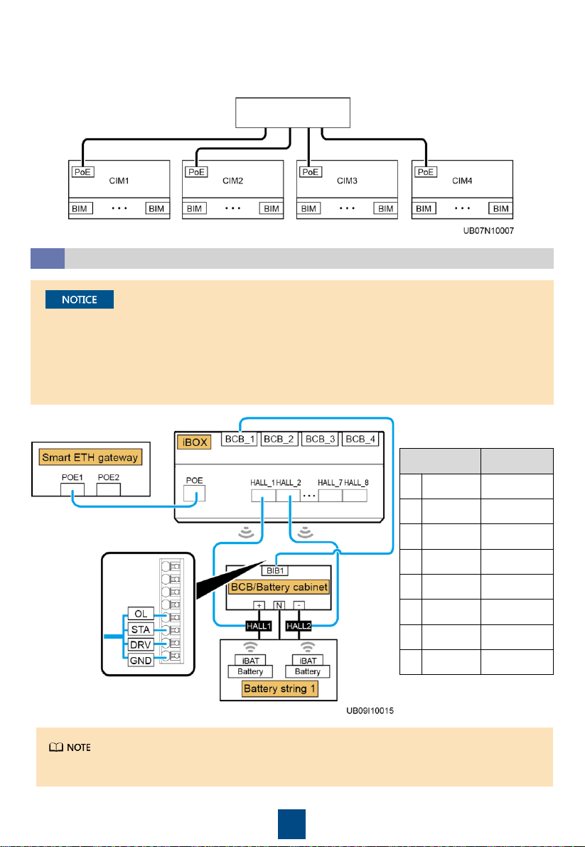
•When selecting a position to install the CIM, ensure that the communication distance between
the CIM and the BIM is not greater than 15 meters.
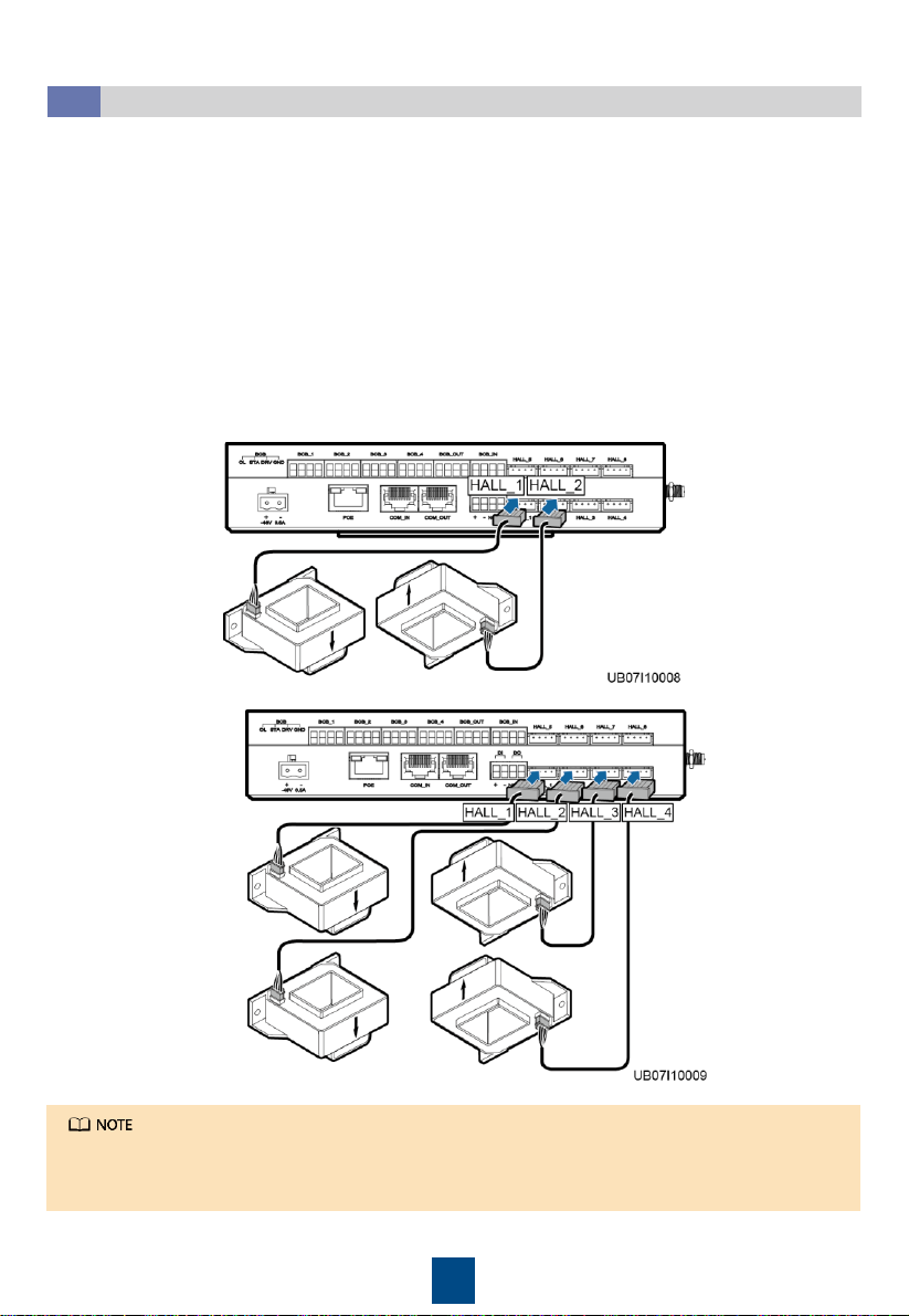
•Dimensions (L x W) of the center hole of the Hall effect sensor are 40.5 mm x 30.5 mm (LEM) or
40.5 mm x 40.5 mm (TAMURA).
•If the battery string is configured with the neutral wire, measure the currents of the positive and
negative battery string cables. If the battery string is not configured with the neutral wire,
measure the current of either the positive or negative battery string cable. The following uses
the scenario where the battery string is configured with the neutral wire as an example.
When installing the CIM in the battery switch cabinet, do not use the delivered antenna. Attach the
external antenna to the top of the battery switch cabinet, and connect the antenna cable to the
RF_Z port on the CIM.
Installing a BIM
3.2
Installing a BIM by referring to section 2.2 "Installing a BIM."
Installing a CIM
3.3
Installing a CIM by referring to section 2.3 "Installing a CIM."
Installing a Hall Effect Sensor
3.4
1. Route the positive and negative battery string cables through the Hall effect sensor. The
positive and negative battery string cables must be routed in directions shown by arrows on the
Hall effect sensors. The positive battery string cable routes from the UPS to the battery, and the
negative battery string cable routes from the battery to the UPS.
2. Secure the Hall effect sensor to the positive and negative battery string cables using cable ties.
If the positive or negative battery string cable is too thick to be routed through the Hall effect
sensor, or the measurement range of the Hall effect sensor is insufficient, use multiple Hall effect
sensors to detect the current of one battery string. The CIM supports the sum of the monitoring
results of multiple Hall effect sensors, which is implemented by setting Multi-Hall cur. setting.


 Plus Startup manual")