Huayi LW36A-126 Technical manual

LW36A-126/145/T3150-40
High Voltage SF6 AC Circuit Breaker
Operation Instruction
0HK.412.530SM
Huayi Electric Apparatus Group Co., Ltd.

Operation Instruction
Huayi Electric Apparatus Group
0HK.412.530SM
Name & Model LW36A-126/145
High Voltage SF6 AC Circuit Breaker 1/30
List
1. Summarize…………………………………………………………………………… 2
2.Structure and feature………………………………………………………………… 3
3.Packing, transport and store………………………………………………………… 13
4.Installation……………………………………………………………………………14
5.On site testing after installed…………………………………………………………21
6.Use and maintenance…………………………………………………………………23
7.Technical documents enclosed with products……………………………………… 25
8.Ordering instruction…………………………………………………………………25
Accessories 1 The characteristic of gas SF6
Accessories 2 Installation tools and spare parts list
Accessories 3 Test report of installation and test
j
je
em
my
y_
_l
le
ee
e@
@h
ho
ot
tm
ma
ai
il
l.
.c
co
om
m

0HK.412.530SM
LW36A-126/145
High Voltage SF6 AC Circuit Breaker 2/30
1 Summarize
1. 1 The operation instruction is apply for LW36A-126/145 High voltage SF6 AC circuit breaker.
It detail described the installation and use, maintenance, the safe criterion should be took note
of, the danger maybe happen. People shall read this operation instruction carefully before
install and use the products, be ensure that people were known well to operate the circuit
breaker. If you still have any question or need more detailed information, please contact the
manufacturer.
1. 2 LW36A-126/145 high voltage SF6 AC circuit breaker is suit for 50Hz、110kV power
system, it is a control and protection equipment for power system, it also can be used as
network interconnecting circuit breaker.
1. 3 The circuit breaker accord with the requirements of GB1984-2003《high voltage AC circuit
breaker》and IEC62271-100《high voltage AC circuit breaker》. The circuit breaker insulated by
gas SF6 and arc suppression medium by gas SF6, use self-energy arc suppression principle,
with CT30 spring operating mechanism, the characteristics are high breaking capacity,small
operating power, high reliability.
1. 4 Use ambient environment condition
Normal use ambient environment condition accord with the regulate of GB11022-99《the
common technical requirements of high voltage switch equipments and control equipments
standard》, as follow:
a. ambient environment temperature -25℃~+40℃
b.altitude ≤2500m (126kV); ≤1000m(145kV)
c.windspeed ≯34m/s
d. one day difference in temperature ≯25℃
e.sunlight ≯0.1w/cm2
f.monthaveragerelativehumidity ≯90%
g. earthquake acceleration level ≯0.2g , uprightness ≯0.1g
h.icecoatingthickness ≯10mm
i. atmosphere dirtiness grade not exceed GB5582 standard’s Ⅲgrade
j. installation situation outdoor
If user request special use ambient environment,please contact with manufacturer.
j
je
em
my
y_
_l
le
ee
e@
@h
ho
ot
tm
ma
ai
il
l.
.c
co
om
m

0HK.412.530SM
LW36A-126/145
High Voltage SF6 AC Circuit Breaker 3/30
1. 5 The operation instruction specify “attention” and “warning”,when the content specified
“attention”, if you breach it, it will be inconvenience or little damaged; When the content
specified “warning”, if you breach it, it will be bodily injury or equipment damaged. The attention
and warning will be specified by boldface.
2. Configuration feature
The circuit breaker is 3 phases porcelain vase stanchion type configuration, outdoor design. 3 phases
with a spring operating mechanism, lay at center,3 phase interlock. The circuit breaker insulated by
gas SF6 and arc suppression medium by gas SF6, when operating the gas SF6 in the 3 phase porcelain
vase is interflow, use pointer type density controller to monitoring the pressure and density. Due to use
self-energy arc suppression principle,and optimize designed in the circuit breaker kinetic system, so
enhanced mechanical efficiency availably, reduced operating power in farthest.
2.1 Main technical parameter
sheet1
No. Item Unit Parameter
1 Rated voltage 126/145
to ground 230/2752 Rated power frequency
withstand voltage(1min)between
fracture
265/275
to ground 550/650
3 Rated lightning impulse
withstand voltage between
fracture
630/650
4 The power frequency withstand voltage
when gas SF6 is zero pressure(5min)
kV
95
5 Rated frequency Hz 50
6 Rated current A 3150
7 Phase coefficient 1.5
8 Rated short circuit breaking current 40/31.5
9 Rated short circuit making current 100/80
10 Rated short time withstand current 40/31.5
11 Rated peak withstand current
kA
100/80
12 Rated short circuit continuous time s 4
13 Rated out of synchronism breaking
current
10
14 Short line fault breaking current
kA
36,30
15 Rated line charge breaking current A 31.5
16 Rated operating sequence O-0.3s-CO-180s-CO
17 Switch off time 30±3
18 Switch on time
ms
75±8
j
je
em
my
y_
_l
le
ee
e@
@h
ho
ot
tm
ma
ai
il
l.
.c
co
om
m

0HK.412.530SM
LW36A-126/145
High Voltage SF6 AC Circuit Breaker 4/30
Continuous sheet 1
No. Item Unit Parameter
19 On-off time ms ≤60
20 Main loop resistance µΩ≤40
21 Rated gas SF6 pressure (20℃meter’s
pressure)
0.6
22 Alarm/closedown pressure(20℃
meter pressure)
MPa
0.55 / 0.50
23 Gas SF6 leak annual % ≤1
24 Moisture content of gas ppm(v) ≤150
25 Mechanical life 次6000
26 Wireless interfere level µV ≤500
Between fracture 3150/362527 Creepage
distance To ground
mm
3150/3625
28 Gas SF6 weight of each circuit breaker 10
29 Circuit breaker weight
kg
1300
Main technical parameter of mechanism
sheet 2
No. Item Unit Parameter
1 Auxiliary loop voltage V DC220
2 Rated operating voltage of
switch on coil and switch off coil
V DC220
3 Rated operating current of switch
on coil and switch off coil
A 2
Rated voltage V AC220 /DC220
Voltage range of
normal operation
V 65%~110%
4 Energy
store
motor
Power W 600
5 Energystoretimeofmotor s ≤15
6 Manual energy store moment N·m ≤30
7 Loop voltage of heater and
lighting
V AC 220
8 Rated voltage of auxiliary switch V DC 220
9 Rated current of auxiliary switch A 10
10 Connection point pairs of
auxiliary switch
20
2.2 Whole configuration feature of circuit breaker
The configuration shown as drawing 1, 3 poles porcelain vase install on a common base. The control
box lift on under the center of base, spring operating mechanism and control unit are installed in the
control box, the output pole of mechanism is connect with middle phase’s regulating lever.
j
je
em
my
y_
_l
le
ee
e@
@h
ho
ot
tm
ma
ai
il
l.
.c
co
om
m

0HK.412.530SM
LW36A-126/145
High Voltage SF6 AC Circuit Breaker 5/30
1.pole(porcelain vase) 2.base 3.pointer type density controller 4.control box 5.name plate
Drawing 1 whole configuration drawing of circuit breaker(face)
2.3 base
The base work as support 3 poles and connect control box,made by bended armor plate, covered cover
boards, it can meet GB11022《the common technical requirements of high voltage equipment and
control equipment design standard》IP4X protection grade。The base face can see pressure meter,
name plate and 3 installation holes. The 3 phase gas SF6 charge pipeline and pointer type density
controller are installed in the base. When not connect the pole gas charge valve, the gas in the gas
charge pipeline is in seal state, the pressure meter display data is the pressure of pipeline. There is a
branch joint under the pressure meter, the opening joint is the circuit breaker’s gas charge joint.
j
je
em
my
y_
_l
le
ee
e@
@h
ho
ot
tm
ma
ai
il
l.
.c
co
om
m

0HK.412.530SM
LW36A-126/145
High Voltage SF6 AC Circuit Breaker 6/30
The point type SF6 density controller(with pressure meter) is use for monitoring the density of gas SF6
in equipment and send control signal,it have the function of temperature compensate. When the
ambient temperature change to bring the pressure change of gas SF6, the controller will not act. Only
when the gas SF6 leak to bring pressure change, the controller will alarm and closedown signal.
The control box connect under the base by 6 bolts M20, there are dampproof and dustproof seal
equipment at the joint of mechanism output pole, the joint of B phase regulating lever and the exit of
secondary wire.
Attention:1 When not connect the pole, the pressure meter display data is the pressure of pipeline.
2 the pressure data displayed is at 20℃.
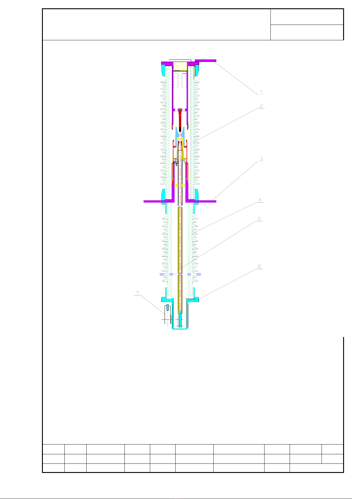
1.4 Pole(porcelain vase)
Each pole is an airtight unit. The pole consist from top to bottom: above output wire plate, explosion
chamber, bottom output plate, support porcelain tube, insulating tie bar, regulating lever box, operating
mechanism etc.(see drawing 2).
2.4.1 Above output wire plate and bottom output wire plate
Above output wire plate and bottom output wire plate are use for line primary connecting,the bottom
output wire plate have output wires on face and inverse(the side of switch on indication and switch off
indication on control box called face, or the side have a pressure meter called face), the output wire
direction of above output wire plate can install according to user’s request. If user haven’t definitely
request, the above output wire plate will be installed at face side. Wire connection hole dimensions of
above output wire plate and bottom output wire plate have 3150A and 1250A two wire connection
types, see drawing 3,the dimension criterion refer to GB5273《connection terminal of transformer, high
voltage electric appliance, bushing》.
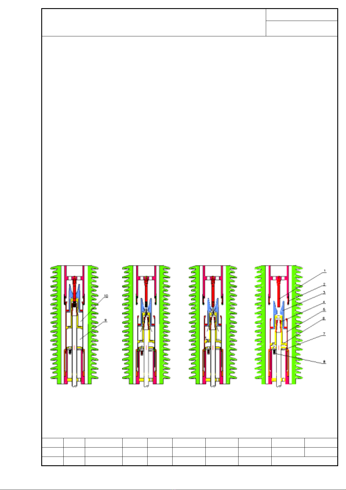
2.4.2 Explosion chamber
Explosion chamber installed in bushing, it is the core part of circuit breaker. It mainly consist by
porcelain tube, fixed contact base, fixed main contact, fixed arc contact, spout, cylinder, moving arc
contact, middle contact, bottom support base, tie bar, etc.(see drawing 4)。 The sorbent is put on the
top of fixed contact base, tie bar is connect with insulated tie bar of support porcelain tube, finally
connect to outer regulating lever. The explosion chamber porcelain tube is made by high strength
porcelain, it is high strength and good airtightness.
j
je
em
my
y_
_l
le
ee
e@
@h
ho
ot
tm
ma
ai
il
l.
.c
co
om
m

0HK.412.530SM
LW36A-126/145
High Voltage SF6 AC Circuit Breaker
7/30
1.above output wire plate 2.explosion chamber 3.bottom output wire plate 4.support porcelain tube
5.insulated tie bar 6.regulating lever box 7.outer regulating lever
drawing 2 pole(porcelain vase)
j
je
em
my
y_
_l
le
ee
e@
@h
ho
ot
tm
ma
ai
il
l.
.c
co
om
m

0HK.412.530SM
LW36A-126/145
High Voltage SF6 AC Circuit Breaker 8/30
drawing 3 connection terminal plate
1. porcelain tube
2. fixed contact base
3. fixed arc contact
4. fixed main contact
5.spout
6.Moving main contact
7.Moving arc contact
8.Middle contact
9.Bottom support base
10. tie bar
drawing 4 configuration drawing of
explosion chamber
j
je
em
my
y_
_l
le
ee
e@
@h
ho
ot
tm
ma
ai
il
l.
.c
co
om
m

0HK.412.530SM
LW36A-126/145
High Voltage SF6 AC Circuit Breaker 9/30
Long term current carrying loop consist by above wire connection plate, fixed contact base, fixed main
contact, cylinder, middle contact, bottom support base, bottom wire connection plate. At the bottom of
cylinder’s thermal expansion chamber installed non-return valve, at the bottom of plenum chamber
installed air return valve and pressure relief device.
2.4.3 Support porcelain tube
Support porcelain tube work as support explosion chamber and insulated to ground. In the porcelain
tube installed insulated tie bar, work as insulated to ground and mechanical drive. The support
porcelain tube is made by high strength porcelain, it is high strength and good airtightness.
2.4.2 Regulating lever box
Regulating lever box work as transfer the operating mechanism’s output action to insulated tie bar, and
finally transfer to moving part of explosion chamber, to complete the circuit breaker’s switch on and
switch off. The regulating lever box installed valve for connecting the gas charge pipeline in base.
When the gas charge pipeline was not connected, the whole pole is in seal state. The regulating lever
shell made by high airtightness aluminium alloy, there are location holes can fixed the pole at the
switch off position.
2.5 The principle of circuit breaker arc suppression(see drawing 5)
A switch on position B breaking heavy current C breaking low current D switch off position
1. fixed arc contact 2. main contact 3. spout 4. moving arc contact 5. cylinder 6. non-return valve
7. pressure relief valve 8. pressure reduce valve 9. plenum chamber 10. thermal expansion chamber
Drawing5 theprincipleofarcsuppression
j
je
em
my
y_
_l
le
ee
e@
@h
ho
ot
tm
ma
ai
il
l.
.c
co
om
m

0HK.412.530SM
LW36A-126/145
High Voltage SF6 AC Circuit Breaker 10/30
When the circuit breaker received an order, the rigidity movement parts which consist by cylinder,
moving arc contact, tie bar will move down under the operation of switch off spring. In the movement,
fixed main contact breakaway with moving main contact, current transfer to two closed arc contacts,
then the arc contact breakaway come into being arc.
When breaking short circuit current, if breaking heavy current, arc energy is big of between arc
contacts, arc zone’s thermal current inrush into thermal expansion chamber and exchange thermal,
come into being low temperature and high pressure gas; here, because the thermal expansion
chamber pressure big than plenum chamber, the non-return valve close. When the current is exceed
zero, the high pressure gas in the thermal chamber blow to fracture to extinguish arc. In switching off,
the plenum chamber’s gas pressure was compressed at begin, when the gas pressure up to a stated
value, the bottom spring pressure relief valve opening, pressure gas and relief gas at same time, so the
mechanism not have to conquer more pressure gas counterforce, thereby reduced operating power
greatly.(see drawing 5B)。
If breaking low current(usually is less than thousands ampere),due to arc energy is small, the pressure
in thermal expansion chamber is low. Here, the plenum chamber’s pressure is higher than thermal
expansion chamber, non-return valve opening, the compressed gas blow to fracture, when the current
exceed zero, make the arc extinguish.(see drawing 5C)。
2.6 Spring operating mechanism
This operation instruction introduced commonly of CT30 spring operating mechanism’s configuration
and principle, the detailed information you can refer to《operation instruction of CT30 spring
operating mechanism》.
The spring operating mechanism install in control box, the operating principle see drawing 6.
2.6.1 Energy store of switch on spring
AC/DC motor drive pawl axis circumrotate, 90°change transfer to big pawl and small pawl, drive
ratchet wheel circumrotate, make the switch on spring compress to store energy by tie bar; past the
dead center position, motor was cut power supply by a sensitive switch.(motor is provided with over
current protection and force cut power supply in 15 seconds.)Ratchet wheel axis is given a
counter-clockwise running moment by switch on spring.
2.6.2 Switch on operating
The switch on coil after electrified, drive switch on detent; the switch on detent to circumrotate
clockwise, release switch on keep detent; jack up B pin to release ratchet wheel, the kept switch on
spring release energy to drive cam circumrotate.
j
je
em
my
y_
_l
le
ee
e@
@h
ho
ot
tm
ma
ai
il
l.
.c
co
om
m

0HK.412.530SM
LW36A-126/145
High Voltage SF6 AC Circuit Breaker 11/30
Cam impinge on trolley to make regulating lever circumrotate clockwise, drive tie bar to switch on
quickly of moving contact and fixed contact, complete switch on operating.
Otherwise, when switching on, the switch off spring connect with regulating lever was compressed and
that store energy.
2.6.3 Switch off operating
The switch off coil after electrified, drive switch on detent; the switch off detent to circumrotate
clockwise, switch off keep detent circumrotate clockwise too, release A pin, inner regulating lever
circumrotate counter-clockwise drove by switch off spring, drive tie bar to switch off quickly of
moving contact and fixed contact, complete switch off operating.
Switch off operating(switch on position, switch on spring store energy)
switchonspringstoreenergy switchonoperating
(switch on position, switch on spring release) (switch off position, switch on spring store energy)
drawing 6 CT30 spring operating mechanism principle sketch map
j
je
em
my
y_
_l
le
ee
e@
@h
ho
ot
tm
ma
ai
il
l.
.c
co
om
m

0HK.412.530SM
LW36A-126/145
High Voltage SF6 AC Circuit Breaker 12/30
2.6.4 reclose operating
When the switch on spring and switch off spring are both in energy stored state,(also is GCB work
state),it complete by throw the dictate of off-0.3s-on and off.
2.7 Control box
Control box installed spring operating mechanism, group terminal block of secondary control loop,
counter(mechanical type), heater, etc parts. Redarding the circuit breaker’s detailed operation methods
and secondary schematic diagram and wire connection diagram, please refer to《operation instruction
of CT30 spring operating mechanism》.
Drawing 7 sketch map of inner control box
j
je
em
my
y_
_l
le
ee
e@
@h
ho
ot
tm
ma
ai
il
l.
.c
co
om
m

0HK.412.530SM
LW36A-126/145
High Voltage SF6 AC Circuit Breaker
13/30
There are manual switch on and switch off button, distance-on the spot changeover switch, energy store
motor switch(see drawing 7),circuit breaker’s state indicator drop on faceplate of control box. The
operator can see the circuit breaker state.
The sketch map and operating method of faceplate in control box, please refer to《operation
instruction of CT30 spring operating mechanism》.
3.Packing, transport and store
3.1 Packing
There are 5 subassembly of circuit breaker packing case, see drawing 8. Three poles(porcelain vase)
packet by wood carton;The random file and packing list are inside the control box. Besides, there is a
accessory box for filling installation and debug tools, expendable and fastener etc accessories.
Attention:1. Each pole(porcelain vase) has charged 0.03~0.05Mpa gas SF6.
2.Poleisinswitch off state, insert locating pin.
3. Switch off spring and switch on spring are in release state, insert safety pin.
Dimension: 3100×780×690mm 4050×2290×880mm 650×300×200mm
Weight:300kg/piece 500kg/piece 100kg/peice
Drawing 8 Packing case
3.2 Transport
The packing case can move by forklift or swing by crane(hoisting bigger than 2 tons),move with
translation and lightly put down. Line-haul transport by car, train, ship, if carried by car, the road
surface should not lower than road standard 3 grade. The packet circuit breaker in transporting, loading
and unloading are not allowed overturn, place upside down, should not be shake and hit consumingly.
Warning:1. the pole(porcelain vase) is brittle, it will be broken if not transported according to
criterion.
2. Transport or translation at charge gas pressure higher than 0.1MPa is strictly prohibited.
j
je
em
my
y_
_l
le
ee
e@
@h
ho
ot
tm
ma
ai
il
l.
.c
co
om
m

0HK.412.530SM
LW36A-126/145
High Voltage SF6 AC Circuit Breaker 14/30
3. 3 Store
If the circuit breaker was not installed immediately after deliveried, the subassembly shall be placed at
indoor. If the condition is not allowed, it also can place at outdoor, but should placed at ventilated
location, avoid wet ground, the wood carton shall be placed on plank and covered by paulin. If store a
long term, the condensation-proof heater shall be used. The longest term shall not exceed half year.
The accessory box shall store at indoor, because the filled accessories are not design for outdoor.
4.Installation
Please check and accept the subassembly and accessories before installing, if you have any question,
please contact manufacturer immediately.
Warning: 1. If the subassembly swing improper, it will be collapsed, maybe will make
subassembly break and fatal accident.
2. Using improper bolts or fasten will make products collapse, maybe will make
subassembly break and fatal accident. Installing fasten shall use the spare part of accessory box
which supplied by manufacturer, and fixed by moment spanner. The bolt strength shall 8.8 grade
or higher, fasten moment as follows:
M6 8±1Nm
M8 22±2Nm
M10 45±5Nm
M12 70±7Nm
M16 200±20Nm
M20 400±40Nm
Attention: 1. In whole installing process must have a professional people guide in installing.
2.When installing pole (porcelain vase) , please use lifter or ladder, the ladder lean
against the pole(porcelain vase) is strictly prohibit.
3.Please don’t hit the porcelain tube by any tools or hoisting equipment.
4.1 Preparing groundwork
The circuit breaker groundwork requirements are shown by drawing 9. The height different of two
groundwork levels shall not exceed 2mm,each groundwork level’s levelness not exceed 2mm. The
8pcs foundations (foot) supplied by manufacturer.
j
je
em
my
y_
_l
le
ee
e@
@h
ho
ot
tm
ma
ai
il
l.
.c
co
om
m

0HK.412.530SM
LW36A-126/145
High Voltage SF6 AC Circuit Breaker 15/30
Outline drawing of circuit breaker Note: 1.base embedding, the M24 screw exserted length is 80mm
with 2 nuts, the base dimensions error is ±1mm.
2. the operating applied force: pull up=1800Kg, horizontal
force=2500Kg. total weight=1300Kg.
3.thecircuitbreakerearthedby50×5zinccoated,flat steel.
4.thedimensionof145KVcircuitbreakermarkedinthe ( ).
Drawing 9 groundwork installation

4.2 Installation of base and control box
Before install base subassembly, remove the covered plastic enswathement, put down 4pcs lifting hole
cover board of two sides of bas and 3pcs hand hole cover board.
Lifting the subassembly a little, take off bottom stow-wood, then lifting it to groundwork, fixed on the
groundwork by 8pcs M24 bolts.
After fixed the base and control box, use gradienter to proofread base level, the base level should not
more than 2mm.
Drawing 10 installing the base on the groundwork
j
je
em
my
y_
_l
le
ee
e@
@h
ho
ot
tm
ma
ai
il
l.
.c
co
om
m

0HK.412.530SM
LW36A-126/145
High Voltage SF6 AC Circuit Breaker 16/30
4.3 Pole (porcelain vase) installing
4.3.1 Inspect before installing
Lifting out the 3 poles, translation to hard ground.
Attention: pad crosstie to two sides of pole, to avoid broken.
Visually inspect the poles, if the poles are broken or crevasse in transporting, please contact
manufacturer in time.
Warning: If charge gas in state of pole broken or crevasse, maybe cause pole explode, endanger
person safety.
Inspecting pole airtightness before installing. The regulating lever box have valve interface for gas
charging, remove the valve protection bolt, open valve (a little), if sound of deflate, indicate the pole
airtightness all right, if not, indicate the pole have leak source or was broken in transporting.
Attention:1 Remove the valve protection bolt before install poles.
2 Fix the drive regulating lever and regulating lever box in switch off state by locating
pin, the poles are in switch off state before installing, don’t draw out the locating
pin in installing.
3 When installing all bolts, pole and base, the surfaces shall paint waterproof glue.
4.3.2 Installing of B phase(middle phase)pole
Installing B phase pole first. B phase pole is provided with double regulating levers and the center hole
distance are 125mm and 100mm. Erect the B phase pole.
Attention: When erecting the B phase pole, mat rubber plate or wood plate at the side of regulating
lever box for avoiding broken in touchdown, the plate thickness shall ≥10mm.
Drawing 11 Pole swing
j
je
em
my
y_
_l
le
ee
e@
@h
ho
ot
tm
ma
ai
il
l.
.c
co
om
m

0HK.412.530SM
LW36A-126/145
High Voltage SF6 AC Circuit Breaker 17/30
Put the pole at the jaw opening of base mid, fix by M20X65 bolts(see drawing 12), bolts thread hole
from down to up, tighten by nut, check the installing dimension according to drawing 12. In switch off
state, connect the two operator links and regulating lever(connection way refer to drawing 13), the
connection φ12 pin lubricate by silicon grease. Don’t draw out the switch off locating pin in
connecting. After finished connection, fix the drive pin by M6 bolt and template.
Warning: 1. when the pole is close the middle hole, moving slowly and lightly, or will broken the
porcelain.
2.Swing in charging gas state (charging gas pressure more than0.1MPa) is strictly prohibited.
3.The M20X65 bolt should under the through hole, or the operator link will touch the bolt in
moving. Fix by 2 special design M20X65 bolts in the side of installed operator link, the other side
fix by 2 M20X65 bolts.
1.phase pole 2.drive pin 3.base 4.operator link 5. B regulating lever 6.mechanism output lever
Drawing 12 installing of phase pole
4.3.3 A、C Installing of A, C phase pole
Erecting the A phase pole, put it at base A phase(face to circuit breaker, left side is A phase),Fix by 2
special design M20X65 bolts in the side of installed operator link, the other side fix by 2 M20X65
bolts.
Connecting the operator link and A phase regulating lever in switch off state, the connect pin φ12
lubricate by silicon grease. Don’t draw out the locating pin in connecting.
The installing of C phase pole is same with A, B phase pole.
When both two of operator link are installed, fix the three phase poles in given moment.
Attention: 1 don’t fix too tighten when fixing the A, C phase pole, because maybe will move the
A, C phase pole for adjusting the connect length windage of operator link.
j
je
em
my
y_
_l
le
ee
e@
@h
ho
ot
tm
ma
ai
il
l.
.c
co
om
m

0HK.412.530SM
LW36A-126/145
High Voltage SF6 AC Circuit Breaker 18/30
2. Put gasket between the regulating lever and operator link when connecting the operator link, to
ensure the operator link’s accept power direction and moving direction are same.(see drawing 13).
1 regulating lever 2 operator linkⅠ3 operator link 4Ⅱdrive pin 5 adjusting gasket
Drawing 13orientation of operator link
4.3.4 Connecting of operating mechanism
Connecting the operating mechanism’s output lever with B phase regulating lever. In connecting, prize
the large regulating lever in mechanism through installing hole, make the joint of output lever up and
down jiggle, thereby connect B phase regulating lever by φ20 pin easily, see drawing 14. After finished
the connection, fix the drive pin by M6 bolts and template.
1 pole 2 base 3 mechanism 4 operator link 5 B phase regulating lever 6 mechanism’s output lever
Drawing 14Connectingofoperatingmechanism
j
je
em
my
y_
_l
le
ee
e@
@h
ho
ot
tm
ma
ai
il
l.
.c
co
om
m
This manual suits for next models
2
Table of contents