Huayi H707 User manual

H707
Loop Calibrator
Instruction
Shenzhen Huayi Instrument Technology Co., Ltd.

1.Safety information
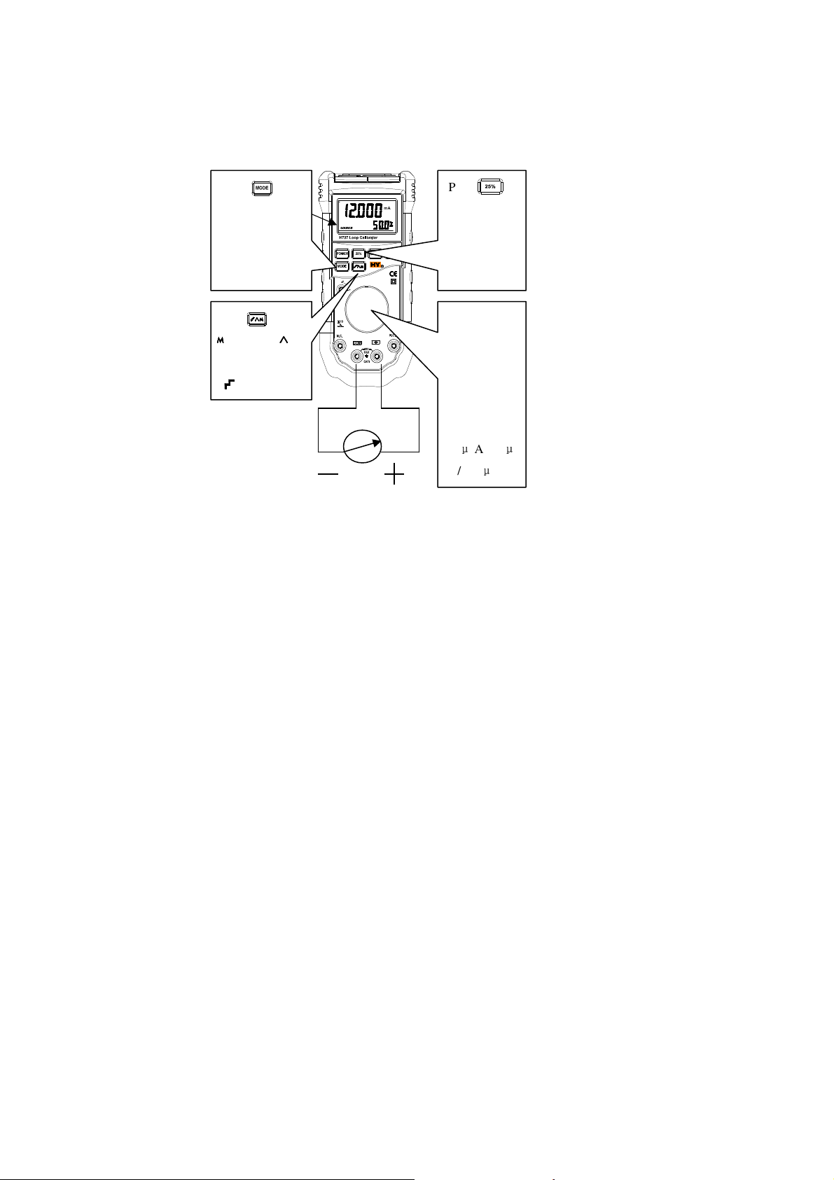
H707 Loop Calibrator (
hereafter to be referred as “Calibrator”
) is an
accurate tool for current supplying and measuring. The calibrator can deliver
source output 0-24mA and simulate two-wire transducer output 0-24mA, and can
measure 0-20mA or 4-20mA current loop, as well as measure DC voltage up to
28V.
This calibrator is an instrument subjects to IEC61010, CAT I 30V and
Pollution grade
Ⅱ
.
1.1 Warnings and notes
To avoid electric shock, personal injury or damage to the calibrator:
• Please use this calibrator following the guidance of this instruction, or the
protection provided by this instrument may be failed.
• Never use this calibrator near explosive gas, vapor or dust.
• Check the calibrator before using, if any damage found, please be sure not to
use.
• Check and test if the insulativity of lead wire is in good condition, and if there
is any damaged or exposed metal. Replace the damaged test wire.
• Never apply voltage above 30 V to between any two terminals or between any
terminal and the earth.
• Be sure to use proper terminal and model when measuring or supplying current.
• To avoid damage to this instrument when testing, it shall set the calibrator to
proper model before connecting the test wire.
• When connecting, it shall connect the COM test wire first, and then connect the
wire to be used; when disconnecting, it shall disconnect the wire to be used
first, and then disconnect the COM test wire.
• Never use this calibrator when the housing cover is open.

• Use the calibrator after confirming that the battery cover is closed.
• Once the symbol (low battery power) appears, please replace the battery
to avoid possible reading error.
• It must remove the test wire from the calibrator before open the housing or
battery door.
1.2
Symbols and marks
Symbol Meaning
Earth ground
Caution: important information, refer to the instruction
Double insulated
Low battery power
Conform to European Union directives
Direct current
2. Description
2.1 Button function
Button Function
Power ON/OFF button.
Start option: setting up the switch off time, for details
please refer to power section.
Backlight ON/OFF button.

Each pressing of this button goes to below mode in turn:
•SOURCE mA (source output mA)
•SIMULATE mA (analog output mA)
•Loop Power (supply loop power)
•MEASURE mA (measure DC mA)
•MEASURE V (measure DC voltage)
By pressing the turncap, the current output could be
adjusted to resolution of 1µA
、
10µA
、
100µA (default value
is 1µA); by rotating the turncap , the current output
could be increased or reduced by 1µA/10µA/100µA.
If turn the turncap in auto slope function or 25% stepping,
the current change direction could be changed.
Press to increase the current with a stepping of 25% of
the full range (0-20mA/4-20mA).
When in full range, press to reduce the current with
stepping of 25% of the full range (0-20mA/4-20mA)
Press to enter into auto slope current output function
and select a slope.
mA slope current output signals that are being continuously
applied or controlled by the calibrator and produced by one
of three below slopes.
(slow), (fast), (stepping) indicate the selected
slope.

Press to start SpanCheck from 0% of selected current
span (e.g., 0mA within 0-20mA span, or 4mA within
4-20mA span), “SpanCheck” will appear.
Press it again, then start from 100%.
+
Press and simultaneously to switch among mA
output spans.
• 4 mA-20 mA =0%-100% (default value)
• 0 mA-20 mA =0%-100% (optional)
The selection will be saved until next change.
2.2 Display
1: show the measured value or output value
2: show the percentage of measured value or
output value account for of the full scale
Symbol Explanation
MEASURE Measure current or voltage
SIMULATE Simulate output current
SOURCE Source output current
SpanCheck Full scale check (0%-100%)
Loop Power Loop power
mA V Unit symbol: mA or V
Auto oblique wave function
Low batter power

3. Use
3.1 mA current output model
The calibrator can output current which may used to calibrate and test 0-20 mA
and 4-20 mA current loop and instrument.
In SOURCE model, The calibrator can supply current.
In SIMULATE model, the calibrator can simulate two-wire transducer which
uses a set of external source.
Change the mA output span
The calibrator has two mA output spans:
• 4 mA-20 mA (0%-100% ) [default value]
• 0 mA-20 mA (0%-100%) [optional]
To change the output span, please press and simultaneously.
The
setting value for selection will be saved before next change.

Supply mA current
Use SOURCE mode to supply current to passive circuit.
There must be path which allows the current to flow between “+”
terminal and COM terminal, or it will show overload (figure flashing)
when you setting up the output value.
Press until
the display
show SORCE
(source output
mA)
Press to select
Slow slope
Fast slope and
Stepping slope
Press or
rotate the
turncap to
change in
the
resolution of
1
μ
A/10
μ
A/100
μ
A
Press to
change in
the stepping
of 25% of
the full scale

Analog transducer
When the calibrator is used as an analog transducer, it can adjust the output loop
current to the known value you selected.
There must be 12-28 V loop source. Please connect the test wires as the figure
below.
Press until
the display
shows
SIMULATE
(analog output
mA)
Press
to
select
Slow slope
Fast slope and
Stepping
slope
Press or rotate
the turncap to
change in the
resolution of 1
μ
A/10
μ
A/100
μ
A
Press to
change in the
stepping of
25% of the full
scale
Power
Max 30V
DC Current

3.2 Auto linear increasing mA output
Auto lope current output allow the calibrator to output passive (supply current)
or active (simulate) loop current that is continuously changing. And you can still
leave your hands free to test calibrator responsibility.
Press to enter into “Auto lope current output” model and step to next slope
type.
The calibrator applies or controls a continuously repeated mA signal in one of
below three slope types within the span of 0-20 mA or 4-20 mA:
Slow slope: gentle slope with rate of change 0%-100%-0% within 40s.
Fast slope: abrupt slope with rate of change 0%-100%-0% within 15s.
Stepping slop: 25% stepping slope with 5s of pause per step.
Press any key or switch off the calibrator to exit this function.
Use “Spancheck” function
“Spancheck” function can be used to check the zero point or span of a calibrator
under SOURCE or SIMULATE model.
To select “Spancheck”, please press .

Press any key or rotate the turncap to exit this function.
3.3 Measure DC current (mA)
Caution
To avoid damage to the device during test, please ensure the calibrator in
proper model before connecting the test wire.
To test mA DC:
1. Prees to step to MEASURE model.
The display shows MEASURE mA.
2. Contact the load circuit or source with the probe of the test wire.
3. If the current over 24mA, it will show “-OL-”.
Press
until the
display
shows
MEASURE
(measure
mA)
24mA DC current in maximum

3.4 Measure mA current with loop Power
Caution
To avoid damage to the device during test, please ensure the calibrator in proper
model before connecting the test wire.
Under this model, the calibrator can supply +24V loop power to the
transducer,and read the loop current value at the same time.
Measure DC mA current with loop Power scale
1. Press to step to Loop Power model.
The display shows MEASURE with unit mA (measure mA) and Loop
Power.
2. Contact the load circuit or source with the probe of the test wire.
3. If the current over 24mA, it will show “-OL-”.
30V DC voltage in maximum
Press until
the display
shows
MEASURE
(measure mA)
Loop Power
(use loop
power)
Two-wire transducer

3.5 Measure DC voltage
Caution
To avoid damage to the device during test, please ensure the calibrator in
proper model before connecting the test wire.
To measure DC voltage
1. Press to step to MEASURE model.
The display shows MEASURE V.
2. Contact the load circuit or source with the probe of the test wire.
3. If the voltage over 28V, it will show “-OL-”.
30V DC voltage in maximum
Press until the
display shows
MEASURE
(measure voltage)
with unit V

3.6 Power
Requirements for the power
Single battery 9V (ANSI/ENDA 1604A or IEC 6LR61)
Battery life (typical value):
Battery model: about 3 hours (500Ωwith load 12 mA);
MEASURE/SIMULATE: 7 hours
Setting for battery power-saving function
By default, the calibrator will be auto-off after using for 15 minutes after switch
on:
1. When the calibrator is off, press + to switch on.
The display shows PS-XX
,
in which XX indicates the switch-of time with unit
minute. OFF indicates that the power protector is disabled.
2. Rotate the turncap to reduce or increase the switch-off time, of which the
shortest is 5minutes, while the longest is 30 minutes.
3. To disable this function, please rotate the turncap until the display shows OFF.
4. The calibrator will exit switch-off setting automatically about 5s later, and you
may also press the turncap to do it.

4.
Accuracy specification
The accuracy is only applicable to 1 year after calibration with operation
temperature 18
℃
-28
℃
, which shown as ± ([% of the reading]+[count]).
4.1 MEASURE V dc
Range: 0 — +28V
Resolution: 1mV (mV)
Input impedance: 1MΩ
Accuracy: ± (0.02% of the reading +4 counts)
4.2 MEASURE mA dc
Range: 0 — +24mA (24mA in maximum)
Resolution: 1uA
Accuracy: ± (0.02% of the reading +4 counts)
4.3 SOURCE / SIMULATE mA dc
Range: 0 — +24mA
Resolution: 1uA
Accuracy: ± (0.02% of the reading +4 counts)
SOURCE MODE iswith load ability:
When the current is 20mA, the impedance is 1200Ω; when under HART
model with current 20mA, the impedance turns to 950Ω.
External loop voltage specification under Simulate mode:
Typically 24V, max 30V, min 12V.
4.4 Loop Power: ≥24V, ≤30V.
4.5 General specifications
The voltage between any terminal and the earth or between any two terminals:
not higher than 30V.
Storage temperature: -40
℃
-60
℃

Operation temperature: -10
℃
-55
℃
Operation elevation: max 2000m in height
Temperature coefficient: 0.005%×range/
℃
(-10
℃
—18
℃
or 28
℃
—55
℃
).
Relative humidity: 95%-30
℃
, 75%-40
℃
,
45%-50
℃
, 35%-55
℃
.
Vibration: random sampling 2 grams, 5-500Hz
Impact: 1m free drop test
Size: 195(L)×92(W)×55(H) mm
Weight: about 400g, (including the rubber cover).
Conformity to safety standards:
Meet the standard of IEC 61010-1-95 CAT I, 30V;
Meet the standard of EN61010-1 EN61326.
5. Maintenance and calibration
5.1 Repair
To avoid electric shock, personal injury or damage to the calibration, please
be sure to make this product repaired by qualified technican according to the
instruction, and must prepare necessary devices and service information. Before
open the housing, it must remove the test wire and all input signals in advance.
For repair procedures not referred in this instruction, please contact the
service center.
5.2 Cleaning
It shall clean the housing of calibrator with wet cloth and detergent
regularly, never use corrosive or solvent. Never make water leak in the
calibrator.
5.3 Replace the battery
Once the symbol (low battery power) appears, please replace the

battery immediately to avoid reading error which may cause electric shock or
personal injury.
The calibrator uses one 9V alkaline battery (ANSI/NEDA 1604A or IEC
6LR61), if want to replace this battery, please follow below steps:
1.Press to switch off the calibrator.
2. Disconnect the test wire from the terminal.
3. Remove the rubber cover.
4. Unscrew the two screws fastening the battery cover with screwdriver, then
open the door at the back of this calibrator, see below figure.
5. Take out the used battery.
6. Put in the replacing battery, close the battery door. Ensure that the battery
fastened in place.
7. Fit the cover, drive the screws to the cover tightly .
8. Put back the calibrator into the rubber cover.
9V
电池
电池电池
电池
电池盖
电池盖电池盖
电池盖

5.4 Setting up HART model
If want to enable or disable the HART model of Calibrator (Highway
Addressable Remote Transducer), please operate as follows:
1.Press to switch off the calibrator and disconnect the test wire.
2. Take out the calibrator from the rubber cover.
3. Remove the battery from the device, shown as above figure.
4. Unscrew four screws from the bottom housing.
4. Separate the bottom housing form the top housing.
5. Pick up the short-circuit cap, then move it to enable (or disable) HART model
(see figure).
6. Case the bottom housing on the top housing, then re-drive the four screws.
7. Fit the battery door, then put it in the rubber cover.
HART mode: short-circuit cap
connected to the right,
disabled; short-circuit cap
connected to the left, enabled
Circuit board

5.5 Calibration
It shall implement calibration on the calibrator to confirm if its function meets
the specification, for details please refer to the factory.
6. Accessories included
Item Description Lot No. Quantity
1
9V alkaline cell (ANSI
/NEDA 1604A or IEC 6LR61)
1
2
Test lead wire set
1
3
Instruction
1
4
Certification
1

Shenzhen Huayi Instrument Technology Co., Ltd.
Address: Building 3, West Floor 9, SEG Technology Industrial Park, North
Huaqiang Road, Shenzhen City (518028)
Tel: 86-755-83769588
Fax: 86-755-83768150
Website: WWW.SZHYTECH.NET
Table of contents