DH Instruments ADCS-601 User manual

© 2005 DH Instruments, Inc.
ADCS-601™
Air Data Calibration Standard
Operation and Maintenance Manual

ADCS-601™ OPERATION AND MAINTENANCE MANUAL
© 2005 DH Instruments, Inc
Pressurized gases are potentially hazardous. Energy stored in these gases can be released
unexpectedly and with extreme force. Pressurized systems should be assembled and operated only by
personnel who have been instructed in proper safety practices.
©2005 DH Instruments, Inc. All rights reserved.
Information in this document is subject to change without notice. No part of this document may be reproduced or transmitted in any
form or by any means, electronic or mechanical, for any purpose, without the express written permission of DH Instruments, Inc.
4765 East Beautiful Lane Phoenix Arizona 85044-5318 USA.
DH Instruments makes sincere efforts to ensure the accuracy and quality of its published materials; however, no warranty,
expressed or implied, is provided. DH Instruments disclaims any responsibility or liability for any direct or indirect damages
resulting from the use of the information in this manual or products described in it. Mention of any product or brand does not
constitute an endorsement by DH Instruments of that product or brand. This manual was originally composed in English and was
subsequently translated into other languages. The fidelity of the translation cannot be guaranteed. In case of conflict between the
English version and other language versions, the English version predominates.
DH Instruments, DH, DHI, ADCS-601, ADCS Tools, AMH, COMPASS, FPG8601, PG7601, PPC3 and RPM4 and are trademarks,
registered and otherwise, of DH Instruments, Inc.
Swagelok and Nupro are registered trademarks of the Swagelok Company.
Krytox is a registered trademark of the Dupont de Nemours Company.
Windows, Excel, Word are registered trademarks of the Microsoft Corporation.
Products described in this manual are manufactured under international patents and one or more of the following U.S.
patents: 6,701,791, 5,142,483, 5,257,640, 5,331,838, 5,445,035. Other U.S. and international patents pending.
Document No. 550139b
051222
Printed in the USA

TABLE OF CONTENTS
Page I © 2005 DH Instruments, Inc.
T
TA
AB
BL
LE
E
O
OF
F
C
CO
ON
NT
TE
EN
NT
TS
S
TABLE OF CONTENTS...............................................................I
TABLES..................................................................................V
FIGURES................................................................................VI
ABOUT THIS MANUAL .............................................................IX
1. INTRODUCTION .................................................................1
1.1 SPECIFICATIONS....................................................................................................................................1
1.1.1 ADCS SYSTEM GENERAL SPECIFICATIONS............................................................................................1
1.1.2 PG7601 PISTON GAUGE SPECIFICATIONS...............................................................................................2
1.1.2.1 AMBIENT AND PISTON-CYLINDER CONDITION MEASUREMENTS ....................................................2
1.1.2.2 PISTON-CYLINDER MODULE..................................................................................................................2
1.1.2.3 MASS SET.................................................................................................................................................3
1.1.3 FPG8601 GENERAL SPECIFICATIONS.......................................................................................................3
1.1.3.1 AMBIENT AND PISTON-CYLINDER CONDITION MEASUREMENTS ....................................................3
1.1.4 PRESSURE MEASUREMENT AND CONTROL SPECIFICATIONS............................................................3
1.1.4.1 10 TO 380 KPA, PG7601 AND PPC3-700K ..............................................................................................3
1.1.4.2 1 TO 15 KPA, FPG8601 AND PPC3-100K................................................................................................4
2. SYSTEM OVERVIEW ...........................................................5
2.1 ADCS-601 SYSTEM.................................................................................................................................5
2.1.1 REFERENCE BENCH..................................................................................................................................12
2.1.2 CONTROL CABINET...................................................................................................................................13
2.1.3 GAS SUPPLY PANEL .................................................................................................................................15
2.2 PRESSURE STANDARDS.....................................................................................................................16
2.2.1 PG7601 PISTON GAUGE............................................................................................................................16
2.2.1.1 PG7601 PLATFORM................................................................................................................................17
2.2.1.2 PG7601 TERMINAL.................................................................................................................................17
2.2.1.3 PG7601 10 KPA/KG PISTON-CYLINDER MODULE...............................................................................18
2.2.1.4 AMH-38 AUTOMATED MASS HANDLER...............................................................................................19
2.2.1.5 AMH-38 MASS SET.................................................................................................................................21
2.2.2 FPG8601 FORCE BALANCED PISTON GAUGE.......................................................................................21
2.2.2.1 FPG8601 PLATFORM .............................................................................................................................23
2.2.3 PPC3 PRESSURE CONTROLLERS...........................................................................................................23
2.2.4 RPM4 A116K REFERENCE PRESSURE MONITOR..................................................................................25
2.3 VACUUM PUMPS ..................................................................................................................................27
3. INSTALLATION ................................................................ 29
3.1 UNPACKING AND INSPECTION...........................................................................................................29
3.1.1 ADCS CONTROL CABINET........................................................................................................................30
3.1.2 ADCS REFERENCE BENCH AND ACCESSORIES...................................................................................30
3.1.3 PG7601 PLATFORM AND BELL JAR ........................................................................................................32
3.1.4 PG7601 PISTON-CYLINDER MODULE (PC-7100/7600-10,TC) ................................................................32
3.1.5 PG7601 MASS SET (MS-AMH-38)..............................................................................................................33
3.1.6 PG7601 AUTOMATED MASS HANDLER (AMH-38)..................................................................................34
3.1.7 FPG8601 PLATFORM, PISTON-CYLINDER AND ACCESSORIES...........................................................34
3.1.8 FPG8601 MASS SET (MS-8601-2)..............................................................................................................35
3.1.9 SCROLL VACUUM PUMPS........................................................................................................................35
3.1.10 TURBO MOLECULAR VACUUM PUMP.....................................................................................................35
3.1.11 SYSTEM CONTROLLER.............................................................................................................................36
3.2 SITE REQUIREMENTS..........................................................................................................................36

ADCS-601™ OPERATION AND MAINTENANCE MANUAL
© 2005 DH Instruments, Inc. Page II
3.3 SETUP....................................................................................................................................................38
3.3.1 POSITION THE REFERENCE BENCH.......................................................................................................38
3.3.2 INSTALL REFERENCE TURBO VACUUM AND ROUGHING PUMPS......................................................39
3.3.3 POSITION THE PG7601 AND FPG8601 PLATFORMS ON THE REFERENCE BENCH..........................40
3.3.4 PREPARE FPG8601....................................................................................................................................40
3.3.5 MAKE PNEUMATIC INTERCONNECTIONS ON THE REFERENCE BENCH...........................................41
3.3.6 POSITION CONTROL CABINET AND MAKE PNEUMATIC, COMMUNICATIONS AND ELECTRICAL
CONNECTIONS TO REFERENCE BENCH................................................................................................42
3.3.7 CONNECT PRESSURE SUPPLIES TO CONTROL CABINET...................................................................43
3.3.8 APPLY SUPPLY PRESSURES AND CHECK GAS SUPPLY PANEL SETTINGS ....................................43
3.3.9 SET UP THE PG7601..................................................................................................................................44
3.3.9.1 PREPARE THE PLATFORM AND INSTALL THE PISTON-CYLINDER MODULE.................................44
3.3.9.2 INSTALL THE AMH-38 MASS SET.........................................................................................................44
3.3.9.3 INSTALL THE AMH-38 MASS HANDLER...............................................................................................45
3.3.9.4 INSTALL THE REFERENCE VACUUM CDG ASSEMBLY .....................................................................46
3.3.10 COMPLETE FPG8601 SETUP....................................................................................................................47
3.3.10.1 INSTALL THE PISTON-CYLINDER.........................................................................................................47
3.3.10.2 CONNECT THE MANIFOLD AND VALVE 9............................................................................................47
3.3.10.3 INSTALL THE REFERENCE VACUUM CDG ASSEMBLY .....................................................................48
3.3.11 COMPLETE REFERENCE VACUUM INTERCONNECTIONS ...................................................................49
3.3.12 INSTALL THE UTILITY VACUUM PUMP....................................................................................................49
3.3.13 SET UP THE SYSTEM CONTROLLER (PC) ..............................................................................................49
3.4 POWER UP, INITIALIZATION, VERIFICATION ....................................................................................50
3.4.1 MAIN POWER SWITCHES..........................................................................................................................50
3.4.2 SET OR VERIFY DEVICE COMMUNICATION PORT AND OTHER SETTINGS .......................................50
3.4.2.1 COMMUNICATION PORTS.....................................................................................................................50
3.4.2.2 PG7601 EXTERNAL VACUUM GAUGE COMMUNICATION .................................................................50
3.4.2.3 EDIT AND SELECT PG7601 SETUP FILE..............................................................................................51
3.4.3 PG7601 ........................................................................................................................................................51
3.4.3.1 POWER UP..............................................................................................................................................51
3.4.3.2 INITIALIZATION.......................................................................................................................................51
3.4.4 FPG8601......................................................................................................................................................52
3.4.4.1 POWER UP..............................................................................................................................................52
3.4.5 START UP SYSTEM CONTROLLER AND SOFTWARE............................................................................52
3.4.6 VERIFY SYSTEM OPERATION ..................................................................................................................53
3.5 ENTER VALUE OF LOCAL GRAVITY ..................................................................................................54
3.6 SPECIFY TEST GAS SPECIES.............................................................................................................55
3.7 ADDITIONAL PRECAUTIONS TO TAKE BEFORE MAKING PRESSURE MEASUREMENTS...........55
3.8 SHUT DOWN AND RESTART...............................................................................................................55
3.8.1 RESTART.....................................................................................................................................................55
3.8.2 SHUT DOWN ...............................................................................................................................................56
3.8.2.1 SHORT TERM SHUT DOWN ..................................................................................................................56
3.8.2.2 LONG TERM SHUT DOWN.....................................................................................................................56
4. OPERATION..................................................................... 57
4.1 GENERAL OPERATING PRINCIPLES..................................................................................................57
4.1.1 SYSTEM CONFIGURATION........................................................................................................................57
4.1.2 READY/NOT READY INDICATIONS...........................................................................................................57
4.1.2.1 OVERVIEW..............................................................................................................................................57
4.1.2.2 READY/NOT READY WHEN USING THE PG7601 PISTON GAUGE....................................................57
4.1.2.3 READY/NOT READY WHEN USING THE FPG8601 FORCE BALANCED PISTON GAUGE................58
4.1.3 TRANSITION BETWEEN STANDARDS, ACTIVE AND INACTIVE STANDARD.......................................58
4.1.4 DIFFERENCE BETWEEN REQUESTED AND ACTUAL SET PRESSURE ...............................................60
4.1.5 ASOLUTE AND GAUGE MEASUREMENT MODES ..................................................................................60
4.2 FREQUENTLY USED FUNCTIONS.......................................................................................................61
4.2.1 CONNECTING A DEVICE UNDER TEST (DUT).........................................................................................61
4.2.2 CHANGING PRESSURE UNIT OF MEASURE...........................................................................................61
4.2.3 CHANGING MEASUREMENT MODE (ABSOLUTE, GAUGE)...................................................................62
4.2.4 SETTING PRESSURES...............................................................................................................................62
4.2.4.1 SETTING ZERO PRESSURE..................................................................................................................63
4.2.4.2 SETTING IDLE STATUS..........................................................................................................................63
4.2.5 PRESSURE EXERCISING THE DEVICE UNDER TEST............................................................................63
4.2.6 SETTING A HEAD CORRECTION ..............................................................................................................64
4.2.7 STOPPING PRESSURE CONTROL, ABORTING FUNCTION EXECUTION.............................................64
4.2.8 SECURITY, USER RIGHTS.........................................................................................................................65
4.2.8.1 SETTING UP USERS AND MANAGING USER RIGHTS........................................................................65
4.2.8.2 CHANGING ACTIVE USER.....................................................................................................................66
4.2.9 PRESSURE LEAK TEST.............................................................................................................................66

TABLE OF CONTENTS
Page III © 2005 DH Instruments, Inc.
4.3 LOCAL OPERATION, ADCS TOOLS....................................................................................................67
4.3.1 OVERVIEW..................................................................................................................................................67
4.3.2 MAIN MENU.................................................................................................................................................69
4.3.3 ADCS MAIN TOOLBARS ............................................................................................................................70
4.3.4 ADCS STATUS BAR....................................................................................................................................74
4.3.5 ADCS RUN SCREEN...................................................................................................................................74
4.3.5.1 ADCS RUN SCREEN CONTROL PANEL...............................................................................................75
4.3.5.2 ADCS SYSTEM DISPLAY .......................................................................................................................76
4.3.5.3 ADCS RUN SCREEN TOOLBAR ............................................................................................................78
4.3.6 OTHER DEVICE RUN SCREENS ...............................................................................................................79
4.3.6.1 PG7601 PRESSURE STANDARD...........................................................................................................79
4.3.6.2 FPG8601 PRESSURE STANDARD ........................................................................................................80
4.3.6.3 PPC3 (FPG’S PRESSURE CONTROLLER)............................................................................................80
4.3.6.4 RPM4 REFERENCE PRESSURE MONITOR .........................................................................................81
4.4 AUTOMATED TESTING ........................................................................................................................82
4.4.1 SETTING UP TO RUN AUTOMATED TESTS.............................................................................................82
4.4.1.1 SETTING UP DEVICE UNDER TEST (DUT)...........................................................................................82
4.4.1.2 SETTING UP TEST DEFINITIONS..........................................................................................................84
4.4.1.3 SETTING UP SUPPORT DEVICES.........................................................................................................85
4.4.1.4 TEST OPTIONS (DATA OPTIONS).........................................................................................................85
4.4.2 RUNNING AUTOMATED TESTS ................................................................................................................86
4.4.2.1 RUNNING A MANUAL TEST...................................................................................................................87
4.4.2.2 RUNNING A TEST DEFINITION..............................................................................................................87
4.4.3 TEST RUN SCREENS.................................................................................................................................88
4.4.3.1 DATA PLOT RUN SCREEN.....................................................................................................................89
4.4.3.2 DATA GRID RUN SCREEN.....................................................................................................................89
4.4.3.3 DUT/REFERENCE COMPARISON RUN SCREEN ................................................................................90
4.4.4 TEST DATA..................................................................................................................................................91
4.4.5 REPORT EDITOR........................................................................................................................................91
4.4.6 RUNNING A MODEL 3682 AIR DATA CALIBRATOR................................................................................92
4.4.6.1 RUNNING A VALIDATION (CALIBRATION) ...........................................................................................92
4.4.6.2 RUNNING A STANDARDIZATION..........................................................................................................97
5. REMOTE OPERATION ......................................................103
6. GENERAL MAINTENANCE AND ADJUSTMENTS ..................105
6.1 SUMMARY...........................................................................................................................................105
6.2 FPG8601, CHECK BUBBLER AND ADD WATER IF NECESSARY...................................................106
6.3 FPG8601, REMOVE CLEAN AND REINSTALL THE PISTON-CYLINDER........................................107
6.3.1 OVERVIEW................................................................................................................................................107
6.3.2 REMOVING THE PISTON-CYLINDER FROM THE MOUNTING POST...................................................109
6.3.3 REMOVING THE PISTON FROM THE CYLINDER ..................................................................................111
6.3.4 CLEANING THE PISTON AND CYLINDER..............................................................................................112
6.3.5 PUTTING THE PISTON INTO THE CYLINDER........................................................................................113
6.3.6 INSTALLING THE PISTON-CYLINDER IN THE MOUNTING POST.................................................114
6.3.7 RESTORING PISTON-CYLINDER LUBRICATION AND MOBILITY........................................................115
6.3.7.1 OVERVIEW............................................................................................................................................115
6.3.7.2 PISTON CENTERING AND LUBRICATING METHODS.......................................................................115
6.4 PG7601, DISASSEMBLE PLATFORM AND REMOVE MOUNTING POST PRT................................117
6.5 PG7601, REMOVE AND REINSTALL THE AUTOMATED MASS HANDLER AND MASS SET ........118
6.5.1 THE MASS HANDLER (AMH)...................................................................................................................118
6.5.2 THE MASS SET.........................................................................................................................................121
6.6 PG7601, REMOVE, CLEAN AND REINSTALL THE PISTON-CYLINDER MODULE.........................122
6.6.1 REMOVING THE PISTON-CYLINDER MODULE .....................................................................................122
6.6.2 INSTALLING THE PISTON-CYLINDER MODULE ...................................................................................123
6.6.3 DISASSEMBLING THE MODULE AND CLEANING THE PISTON-CYLINDER ASSEMBLY..................124
6.6.3.1 OVERVIEW............................................................................................................................................124
6.6.3.2 DISASSEMBLING AND REASSEMBLING THE MODULE ...................................................................124
6.6.3.3 LUBRICATING THE PISTON-CYLINDER MODULE.............................................................................127
6.6.3.4 CLEANING THE PISTON-CYLINDER...................................................................................................128
6.7 PG7601, PISTON POSITION DETECTION ADJUSTMENT................................................................130
6.8 PG7601, REPLACE PISTON ROTATION DRIVE BELTS...................................................................131
6.9 PG7601, ADJUST INTERNAL VACUUM GAUGE...............................................................................131
6.10 PG7601/FPG8601, ADJUST PPC3 PRESSURE CONTROLLERS.....................................................132

ADCS-601™ OPERATION AND MAINTENANCE MANUAL
© 2005 DH Instruments, Inc. Page IV
6.11 CONTROL CABINET, INTERRUPTING PRESSURE SUPPLY TO THE TEST GAS SUPPLY PORT133
6.12 CONTROL CABINET, DRAIN DRIVE AIR TRAPS..............................................................................133
6.13 CONTROL CABINET, CHECK GAS SUPPLY PANEL SETTINGS.....................................................133
7. MAINTENANCE OF TRACEABILITY AND RECALIBRATION...135
7.1 PRINCIPLES OF ADCS-601 TRACEABILITY MAINTENANCE..........................................................135
7.2 LOCAL METROLOGY MAINTENANCE BETWEEN RECALIBRATIONS ..........................................135
7.2.1 OVERVIEW................................................................................................................................................135
7.2.2 FPG8601, ZERO AND ADJUST SPAN OF LOAD CELL..........................................................................136
7.2.2.1 AUTOMATICALLY INITIATED LOAD CELL ZERO AND SPAN ADJUSTMENT...................................136
7.2.2.2 OPERATOR INITIATED LOAD CELL ZERO AND SPAN ADJUSTMENT ............................................137
7.2.3 FPG8601, VALIDATE WITH PG7601........................................................................................................137
7.2.3.1 OVERVIEW............................................................................................................................................137
7.2.3.2 RUNNING VALIDATION........................................................................................................................138
7.2.3.3 VIEWING FPG VALIDATION DATA ......................................................................................................141
7.2.4 FPG8601, CHECK ON-BOARD P, T, H MEASUREMENTS.....................................................................141
7.2.5 FPG8601, VALIDATE LOAD CELL LINEARITY.......................................................................................141
7.2.5.1 OVERVIEW............................................................................................................................................141
7.2.5.2 LINEARITY VERIFICATION PROCEDURE...........................................................................................142
7.2.5.3 EVALUATING LINEARITY VERIFICATION DATA................................................................................142
7.2.6 FPG8601 AND PG7601, ZERO REFERENCE VACUUM CDGS..............................................................143
7.2.7 PG7601, ADJUST ON-BOARD P, T, H SENSORS...................................................................................146
7.3 RECALIBRATION................................................................................................................................147
7.3.1 OVERVIEW................................................................................................................................................147
7.3.2 PG7601, CALIBRATION OF PISTON-CYLINDER MODULE ...................................................................148
7.3.2.1 PREPARING FOR CALIBRATION.........................................................................................................148
7.3.2.2 UPDATING PISTON-CYLINDER CALIBRATION INFORMATION........................................................148
7.3.3 PG7601, CALIBRATION OF MASS SET...................................................................................................149
7.3.3.1 PREPARING FOR CALIBRATION.........................................................................................................149
7.3.3.2 UPDATING MASS SET CALIBRATION INFORMATION ......................................................................150
7.3.4 PG7601, CALIBRATION OF PISTON-CYLINDER MODULE TEMPERATURE SENSOR.......................151
7.3.4.1 OVERVIEW............................................................................................................................................151
7.3.4.2 PROCEDURE ........................................................................................................................................152
7.3.4.3 CALCULATING AND UPDATING PISTON-CYLINDER TEMPERATURE SENSOR INFORMATION..152
7.3.5 PG7601, CALIBRATION OF REFERENCE VACUUM CDG.....................................................................154
7.3.5.1 OVERVIEW............................................................................................................................................154
7.3.5.2 REMOVING THE CDG ASSEMBLY......................................................................................................154
8. TROUBLESHOOTING .......................................................157
8.1 OVERVIEW ..........................................................................................................................................157
9. APPENDIX ......................................................................159
9.1 CONVERSION OF NUMERICAL VALUES..........................................................................................159
9.1.1 PRESSURE................................................................................................................................................159
9.2 GLOSSARY..........................................................................................................................................160
9.3 WARRANTY STATEMENT..................................................................................................................161

TABLES & FIGURES
Page V © 2005 DH Instruments, Inc.
T
TA
AB
BL
LE
ES
S
Table 1. ADCS-601 packing list.................................................................................................................29
Table 2. Reference Bench parts list...........................................................................................................30
Table 3. Interconnections kit parts list .......................................................................................................31
Table 4. ADCS accessory kit parts list.......................................................................................................31
Table 5. PG7601 Platform parts list...........................................................................................................32
Table 6. PC-7100/7600-10, TC piston-cylinder module parts list..............................................................33
Table 7. MS-AMH-38 mass set parts list ...................................................................................................33
Table 8. AHM-38 automated mass handler parts list ................................................................................34
Table 9. FPG8601 Platform parts list.........................................................................................................34
Table 10. MS-8601-2 mass set parts list...................................................................................................35
Table 11. Valve states................................................................................................................................59
Table 12. User rights user access areas...................................................................................................65
Table 13. ADCS Tools Main Menu and sub-menus summary ..................................................................69
Table 14. ADCS Main Toolbar buttons.......................................................................................................70
Table 15. ADCS Run Screen Control Panel features................................................................................75
Table 16. ADCS System Display symbols.................................................................................................77
Table 17. ADCS Run Screen Toolbar........................................................................................................78
Table 18. Mechanical maintenance procedures......................................................................................105
Table 19. PG7601 mounting post wire colors, description and location..................................................117
Table 20. Gas Supply Panel pressure settings........................................................................................133
Table 21. Metrological maintenance procedures.....................................................................................136
Table 22. FPG8601 P, T, H limits............................................................................................................141
Table 23. Recalibration requirements......................................................................................................147
Table 24. Troubleshooting checklist ........................................................................................................157
Table 25. Pressure unit of measure conversions ....................................................................................159
Table 26. DHI Authorized Service Providers...........................................................................................161

ADCS-601™ OPERATION AND MAINTENANCE MANUAL
© 2005 DH Instruments, Inc. Page VI
F
FI
IG
GU
UR
RE
ES
S
Figure 1. ADCS-601 overall, front view........................................................................................................6
Figure 2. ADCS-601 system pneumatic schematic.....................................................................................7
Figure 3. ADCS-601 simplified operational schematic................................................................................8
Figure 4. ADCS-601 system electrical schematic........................................................................................9
Figure 5. ADCS-601 system communications schematic..........................................................................10
Figure 6. ADCS-601 software, communications and control flow chart....................................................11
Figure 7. Reference Bench, top view.........................................................................................................12
Figure 8. Pneumatic Interconnections Box, bulkhead ...............................................................................13
Figure 9. Control Cabinet, front and rear views.........................................................................................14
Figure 10. Gas Supply Panel.....................................................................................................................15
Figure 11. Piston gauge operating principle..............................................................................................16
Figure 12. PG7601 Platform rear panel.....................................................................................................17
Figure 13. PG7000 Terminal front panel ...................................................................................................17
Figure 14. PG7000 Terminal rear panel....................................................................................................18
Figure 15. PG7601 10 kPa/kg piston-cylinder module..............................................................................18
Figure 16. AMH-38 automated mass handler............................................................................................19
Figure 17. AMH-38 operating principle schematic.....................................................................................20
Figure 18. AMH-38 mass set.....................................................................................................................21
Figure 19. Force balanced piston gauge operating principle.....................................................................22
Figure 20. FPG8601 front and rear views..................................................................................................23
Figure 21. PPC3 front panel ......................................................................................................................24
Figure 22. PPC3 rear panel.......................................................................................................................25
Figure 23. RPM4 front panel......................................................................................................................26
Figure 24. RPM4 rear panel.......................................................................................................................26
Figure 25. Turbo pump local interface panel (local control not used in regular ADCS-601 operation).....28
Figure 26. Typical layout of overall ADCS-601 system at site of use........................................................37
Figure 27. Piston-cylinder module installation...........................................................................................44
Figure 28. Local gravity and pressure medium fields in ADCS Tools .......................................................54
Figure 29. ADCS-601 simplified operational schematic............................................................................59
Figure 30. ADCS Tools pressure exercise definition form..........................................................................64
Figure 31. ADCS Tools pressure leak test results form .............................................................................67
Figure 32. ADCS-601 software, communications and control flow chart..................................................68
Figure 33. ADCS-601 program window.....................................................................................................68
Figure 34. ADCS Main Toolbar..................................................................................................................70
Figure 35. ADCS Status Bar......................................................................................................................74
Figure 36. ADCS Run Screen....................................................................................................................74
Figure 37. ADCS System Display..............................................................................................................78
Figure 38. PG7601 Run Screen.................................................................................................................79
Figure 39. FPG8601 Run Screen ..............................................................................................................80
Figure 40. PPC3 Run Screen ....................................................................................................................81
Figure 41. RPM4 Run Screen....................................................................................................................81
Figure 42. Data Plot Run Screen...............................................................................................................89
Figure 43. Data Grid Run Screen ..............................................................................................................90
Figure 44. DUT/Reference Comparison Run Screen................................................................................90
Figure 45. FPG8601 bubbler and filter ....................................................................................................106

TABLES & FIGURES
Page VII © 2005 DH Instruments, Inc.
Figure 46. FPG8601 piston-cylinder assembly in mounting post............................................................108
Figure 47. Removing the FPG8601 mounting post .................................................................................110
Figure 48. Removing the FPG8601 piston-cylinder.................................................................................110
Figure 49. Alignment of the FPG8601 piston in the cylinder...................................................................113
Figure 50. AMH installation on PG7000 Platform....................................................................................119
Figure 51. AMH mass set ........................................................................................................................122
Figure 52. PG7601 piston-cylinder module installation ...........................................................................123
Figure 53. 10 kPa/kg gas piston-cylinder module, expanded view .........................................................125
Figure 54. 10 kPa/kg piston insertion tool................................................................................................126
Figure 55. 10 kPa/kg gas piston-cylinder module sleeve nut tool ...........................................................126
Figure 56. 10 kPa/kg piston-cylinder module lubrication chart.................................................................128
Figure 57. PG7601 piston stroke and zones ...........................................................................................131
Figure 58. ADCS Tools FPG Run Screen ...............................................................................................137
Figure 59. ADCS Tools FPG Validation Setup Form...............................................................................140
Figure 60. ADCS Tools FPG Validation Results Form............................................................................140
Figure 61. ADCS Tools CDG Zero System Display.................................................................................146
Figure 62. PG7601 Ambient Sensors Adjust Form..................................................................................147
Figure 63. ADCS Tools PG7601 Piston-Cylinder Calibration Form ........................................................149
Figure 64. ADCS Tools PG7601 AMH-38 Mass Set Calibration Form ...................................................151
Figure 65. ADCS Tools PG7601 Piston-Cylinder Calibration Form ........................................................154

ADCS-601™ OPERATION AND MAINTENANCE MANUAL
© 2005 DH Instruments, Inc. Page VIII
N
NO
OT
TE
ES
S
ABOUT THIS MANUAL
Page IX © 2005 DH Instruments, Inc.
A
AB
BO
OU
UT
T
T
TH
HI
IS
S
M
MA
AN
NU
UA
AL
L
This manual provides the information necessary to operate an ADCS-601 Air Data Calibration Standard. The
ADCS-601 is a system made up of several standard instruments. This manual describes the individual
instruments and their operation to the extent necessary for normal operation and maintenance of the
ADCS-601 system. More detailed information on individual instruments and software is contained in each
instrument or program’s specific operation and maintenance manual.
Before using the manual, take a moment to familiarize yourself with the Table of Contents structure. Set
up of an ADCS-601 system should not be attempted without using Section 3. All first time ADCS-601
users should read Section 2. Section 8 is a quick troubleshooting guide. Use the information in Section 8
to troubleshoot unexpected ADCS-601 behavior based on the symptoms of that behavior.
Certain words and expressions have specific meaning as they pertain to ADCS-601 and its instruments.
The Glossary (see Section 9.2) is useful as a quick reference for the definition of specific words and
expressions as they are used in this manual.
Manual Conventions
(CAUTION) is used throughout the manual to identify user warnings and cautions.
(NOTE) is used throughout the manual to identify operating and applications advice and
additional explanations.
[ ] indicates direct function keys or objects (e.g., [RANGE]) on an instrument front panel keypad or in a
software user interface.
< > indicates instrument front panel screen displays or labels in a software user interface (e.g., <1yes>)

ADCS-601™ OPERATION AND MAINTENANCE MANUAL
© 2005 DH Instruments, Inc. Page X
N
NO
OT
TE
ES
S

1. INTRODUCTION
Page 1 © 2005 DH Instruments, Inc.
1
1.
.
I
IN
NT
TR
RO
OD
DU
UC
CT
TI
IO
ON
N
ADCS-601 is a fully automated reference level Air Data Calibration Standard for the verification and
calibration of air data range instruments, in particular Air Data Test Sets (ADTS). ADCS-601’s intended
function is the static pressure calibration of Pt and Ps range pressure transducers with very low measurement
uncertainty. ADCS-601 is not intended to duplicate the functions of an ADTS in calibrating and testing on-
board aircraft instruments.
ADCS-601 covers the pressure range of 1 to 380 kPa (0.3 to 120 inHg) in absolute and gauge modes
with fully automated operation and state of the art uncertainty.
ADCS-601 is an integrated system made up of several instruments that work together under the control of
ADCS Tools software running on a personal computer. Operator interaction with ADCS-601 is accomplished
through the keyboard, pointing device and display of the system controller (personal computer).
The heart of the system is a fully automated PG7601 piston gauge or pressure balance that covers the
range of 15 to 380 kPa (4.5 to 120 inHg). The PG7601 range is extended down to 1 kPa (0.3 inHg) by an
FPG8601 force balanced piston gauge with automated pressure control.
1.1 SPECIFICATIONS
1.1.1 ADCS SYSTEM GENERAL SPECIFICATIONS
Power Requirements
Instruments (AC1)
Reference vacuum pumps (AC2)
Utility pump (AC3)
100 to 240 VAC, 50/60 Hz, 240 W max. consumption
Fuse: 250VT 10A
110 V version: 100 – 120V, 50/60 Hz, 1100 W max. consumption
Fuse: 250VT 10A
220 V version: 200 – 240V, 50/60 Hz, 1100 W max. consumption
Fuse: 250VT 10A
110 V version: 100 – 120V, 50/60 Hz, 800 W max. consumption
Fuse: 250VT 10A
220 V version: 200 – 240V, 50/60 Hz, 800 W max. consumption
Fuse: 250VT 10A
Pressure Supply Requirements Drive air: 0.7 to 1 MPa (100 to 150 psi)
Test gas: Nitrogen or air, 0.45 to 1 MPa (65 to 150 psi), clean and dry
(instrument grade minimum, high purity preferred)
Operating Temperature Range 20 to 26 ºC
Weight Reference bench
Control cabinet
Utility and roughing vacuum pumps
173 kg (380 lb) approx. (with turbo pump and controller installed)
105 kg (230 lb) approx.
19 kg (42 lb) each
Dimensions Reference bench
Control cabinet
145 cm H x 122 cm W x 76 cm D (57 in. x 48 in. x 30 in.)
124 cm H x 56 cm W x 66 cm D (49 in. x 22 in. x 26 in.)
Pressure Ranges Overall
PG7601
FPG8601
1 to 380 kPa (0.3 to 120 inHg)
10 to 380 kPa (3 to 120 inHg)
1 to 15 kPa (0.2 to 4.5 inHg)
Operating Medium Nitrogen or air
Pressure Connections TEST(+) port
TEST(-) port
Quick connector (1/4 in. NUPRO®SS-QC4-B1-400)
Quick connector (1/4 in. NUPRO®SS-QC4-B1-400)
CE Conformance Available, must be specified.

ADCS-601™ OPERATION AND MAINTENANCE MANUAL
© 2005 DH Instruments, Inc. Page 2
1.1.2 PG7601 PISTON GAUGE SPECIFICATIONS
1.1.2.1 AMBIENT AND PISTON-CYLINDER CONDITION
MEASUREMENTS
Temperature Range
Resolution
Measurement Uncertainty
Ambient Piston Cylinder Module
0 to 40o C 0 to 40 oC
0.1 0.01
±1 ±0.1
Barometric Pressure
Range
Resolution
Measurement Uncertainty
70 to 110 kPa
10 Pa
±140 Pa
Relative Humidity Range
Resolution
Measurement Uncertainty
5 to 95 % RH
1 % RH
±10 % RH
Piston Position Range
Resolution
Measurement Uncertainty
±4.5 mm
0.1 mm
±0.2 mm
Piston Rotation
(Rate and deceleration)
Range
Resolution
2 to 99 rpm
1 rpm
Reference Vacuum
(with on-board gauge)
Range
Resolution
Measurement Uncertainty
(with external capacitance
diaphragm gauge) Range
Resolution
Measurement Uncertainty
0 to 20 Pa
0.01 Pa
±0.1 Pa or 10 % of reading, whichever is greater
0 to 13.3 Pa (100 mTorr)
0.001 Pa (0.01 mTorr)
±0.05 Pa (0.38 mTorr)
1.1.2.2 PISTON-CYLINDER MODULE
PC-7100/7600-10
Nominal pressure to mass
Operation
Piston material
Cylinder material
Nominal diameter
Nominal area
Mounting system
Typtical drop rate
Piston assembly nominal mass
10 kPa/kg
Gas operated, gas lubricated
Tungsten carbide
Tungsten carbide
35 mm
1 000 mm2
Positive free deformation
0.2 mm/min
0.5 kg

1. INTRODUCTION
Page 3 © 2005 DH Instruments, Inc.
1.1.2.3 MASS SET
Masses > 50g Material
Finish
Uncertainty in
measured values
304L non-magnetic stainless steel
Electropolished
±5 ppm or 1 mg, whichever is greater
1.1.3 FPG8601 GENERAL SPECIFICATIONS
1.1.3.1 AMBIENT AND PISTON-CYLINDER CONDITION
MEASUREMENTS
Temperature:
Range
Resolution
Accuracy
Lubrication Gas Piston-Cylinder
[°C] [°C]
0 to 40 0 to 40
0.1 0.01
±0.2 ±0.1
Relative Humidity:
Range
Resolution
Accuracy
5 to 95 %RH
1 %RH
±10 %RH
Vacuum:
Range
Resolution
Accuracy
13.3 Pa (100 mTorr)
0.001 Pa (0.01 mTorr)
±0.06 Pa (0.45 mTorr)
Ambient and Lubrication
Pressure Sensor:
Range
Resolution
Accuracy
200 kPa
1 Pa
±0.1 kPa
1.1.4 PRESSURE MEASUREMENT AND CONTROL
SPECIFICATIONS
1.1.4.1 10 TO 380 KPA, PG7601 AND PPC3-700K
Sensitivity1
Precision2
Measurement uncertainty3
Control set point increments
Stability of set pressure
Typical control set point time
0.02 Pa + 0.5 ppm
± (0.01 Pa + 2 ppm)
see the piston-cylinder calibration report and
current revision of DHI Technical Note 7920TN01.
1 kPa
± 1 Pa
60 to 180 seconds
1 Sensitivity: The smallest variation in input detectable in output.
2 Precision: Combined linearity, hysteresis, repeatability.
3 Measurement uncertainty:
Maximum deviation of the indicated pressure from the true value of applied pressure
including all sources of uncertainty combined and expanded (k=2) following the ISO “Guide to the Expression of
Uncertainty in Measurement.”

ADCS-601™ OPERATION AND MAINTENANCE MANUAL
© 2005 DH Instruments, Inc. Page 4
1.1.4.2 1 TO 15 KPA, FPG8601 AND PPC3-100K
Resolution1
Precision2
Measurement uncertainty3
Control set point increments
Stability of set pressure
Typical control set point time
0.01 Pa
± (2 ppm + 50 mPa)
± 0.008% of reading or 0.3 Pa (0.0001 inHg) ,
whichever is larger
1 Pa
± 1 Pa (0.0003 inHg)
60 to 180 seconds
1 Resolution: Minimum display increment.
2 Precision: Combined linearity, hysteresis, repeatability.
3 Measurement uncertainty:
Maximum deviation of the indicated pressure from the true value of applied pressure
including all sources of uncertainty combined and expanded (k=2) following the ISO “Guide to the Expression of
Uncertainty in Measurement.” Note: The uncertainty assigned to the FPG8601 used in an ADCS-601 system is
expanded relative to the standard FPG8601 instrument. to allow validation by the PG7601 and an indefinite
recalibration interval. See Section 7.2.3 and DHI Technical Note 2090TN05.

2. SYSTEM OVERVIEW
Page 5 © 2005 DH Instruments, Inc.
2
2.
.
S
SY
YS
ST
TE
EM
M
O
OV
VE
ER
RV
VI
IE
EW
W
2.1 ADCS-601 SYSTEM
ADCS-601 is a fully automated reference level Air Data Calibration Standard for the verification and
calibration of air data range instruments, in particular Air Data Test Sets (ADTS). ADCS-601’s intended
function is the static pressure calibration of Pt and Ps range pressure transducers. To this end, the
system automatically sets pressure values with very low measurement uncertainty in the range of 1 to
380 kPa (0.3 to 120 inHg) in absolute and gauge modes. ADCS-601 is not intended to duplicate the
functions of an ADTS.
The ADCS-601 system is made up of two automated pressure standards with overlapping ranges to
cover the full pressure range. An automated PG7601 piston gauge covers the range of 15 to 380 kPa
(4.5 to 120 inHg) (see Section 2.2.1). The PG7601 range is extended down to 1 kPa (0.3 inHg) by an
FPG8601 force balanced piston gauge with automated pressure control (see Section 2.2.2). The system
also includes vacuum pumps and vacuum measurement instruments to support absolute mode operation.
An RPM4 Reference Pressure Monitor is included to assist in performing a comparison of the FPG8601
and PG7601 pressure standards.
Physically, the ADCS-601 system is divided into two major components (see Figure 1). The Reference
Bench (see Section 2.1.1) is a laboratory table onto which are installed the PG7601 and FPG8601
pressure standards, pneumatic control switching hardware and the reference vacuum pumping systems.
The Control Cabinet (see Section 2.1.2) contains the PPC3 automated pressure controllers, RPM4
Reference Pressure Monitor and Gas Supply Panel (see Section 2.1.3). The system controller (personal
computer) is connected to the system by a USB interface hub (See Figure 5).
The ADCS-601 system is controlled by ADCS Tools software running on a personal computer (see
Section 4.3.1). ADCS Tools manages the entire system, communicating with other software programs
and system instruments. ADCS Tools also provides the overall system interface through the personal
computers display, keyboard and pointing device.
See the following figures in this section describing the overall ADCS-601 system:
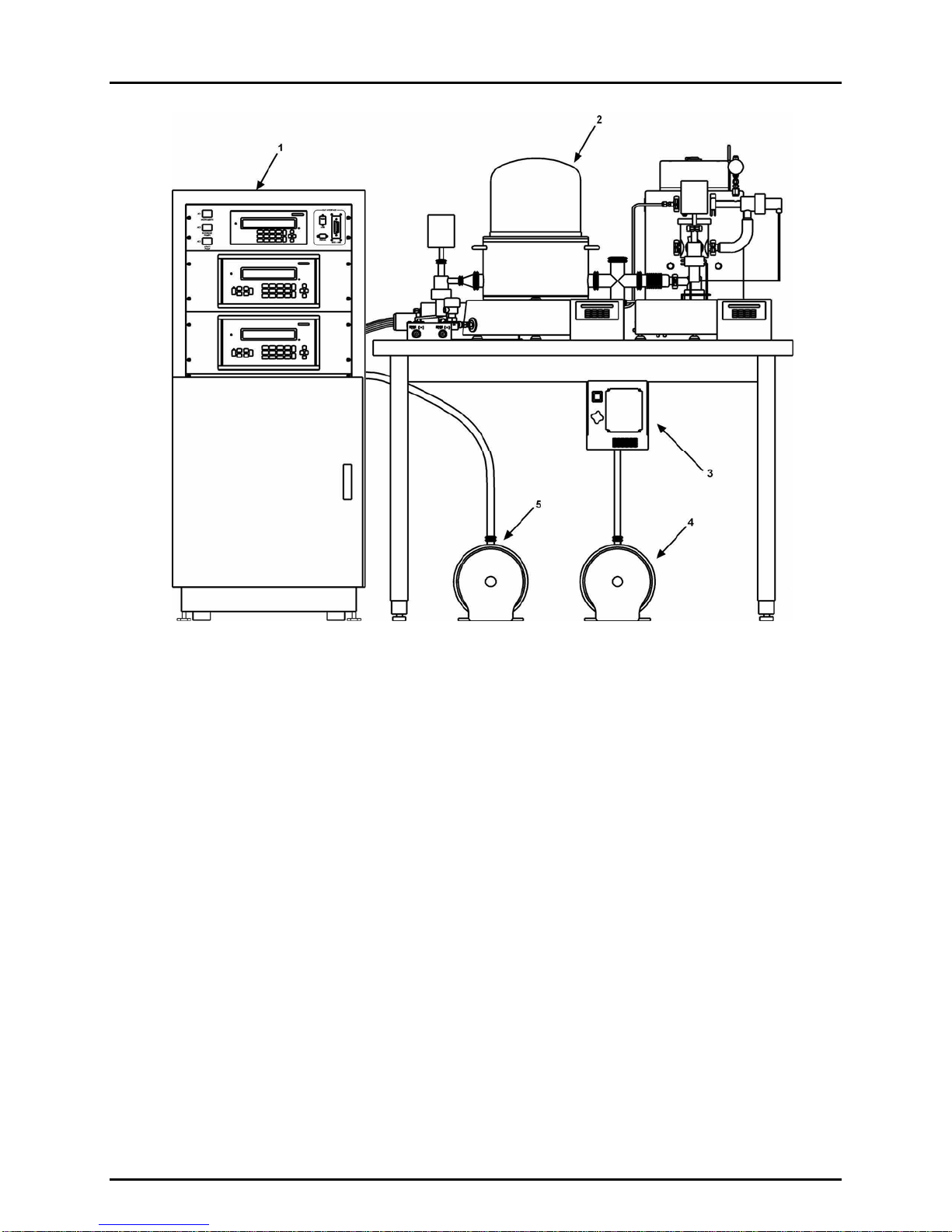
Figure 1. ADCS-601 overall, front view
Figure 2. ADCS-601 system pneumatic schematic
Figure 3. ADCS-601 simplified operational schematic
Figure 4. ADCS-601 system electrical schematic
Figure 5. ADCS-601 system communications schematic
Figure 6.ADCS-601 software and communications, flow chart
Figure 7. Reference Bench, top view
ADCS-601™ OPERATION AND MAINTENANCE MANUAL
© 2005 DH Instruments, Inc. Page 6
1. Control cabinet
2. Reference bench
3. Turbo pump controller and reference
turbo pump (behind controller)
4. Reference roughing vacuum pump
5. Utility vacuum pump
Note: System controller (PC), display and
keypad not shown
Figure 1. ADCS-601 overall, front view
2. SYSTEM OVERVIEW
Page 7 © 2005 DH Instruments, Inc.
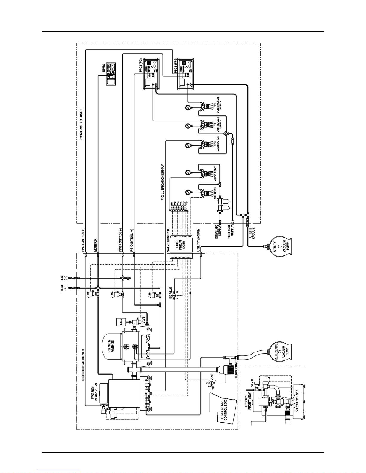
Figure 2.ADCS-601 system pneumatic schematic

ADCS-601™ OPERATION AND MAINTENANCE MANUAL
© 2005 DH Instruments, Inc. Page 8
Figure 3. ADCS-601 simplified operational schematic
Table of contents
Other DH Instruments Test Equipment manuals


Popular Test Equipment manuals by other brands


Martindale Electric
Martindale Electric PD240 instruction manual

Benning
Benning TRITEST easy operating manual

Gossen MetraWatt
Gossen MetraWatt METRISO PRIME 10 operating instructions

Wavetek Wandel Goltermann
Wavetek Wandel Goltermann ANT-20 manual

Extech Instruments
Extech Instruments ExStik CL200 user manual

Hanwei Electronics
Hanwei Electronics AT8070 user manual


