Huazheng HZGZ-IV User manual

HZGZ-IV Portable DC System
Ground-Fault Locator (Split Type)
Instruction Manual

1
Part 1. Overview
Nowdays, the core problem of electric power system DC power supply's
ground-fault trouble shooting is that the interference is big on the site. The
measure result under different DC power supply and different working condition
is poor anti-jamming which leads to misdetect and misjudgement. This is the
biggest drawback and the most common phenomenon of this series of product.
However our product successfully resolved the interference problem so that we
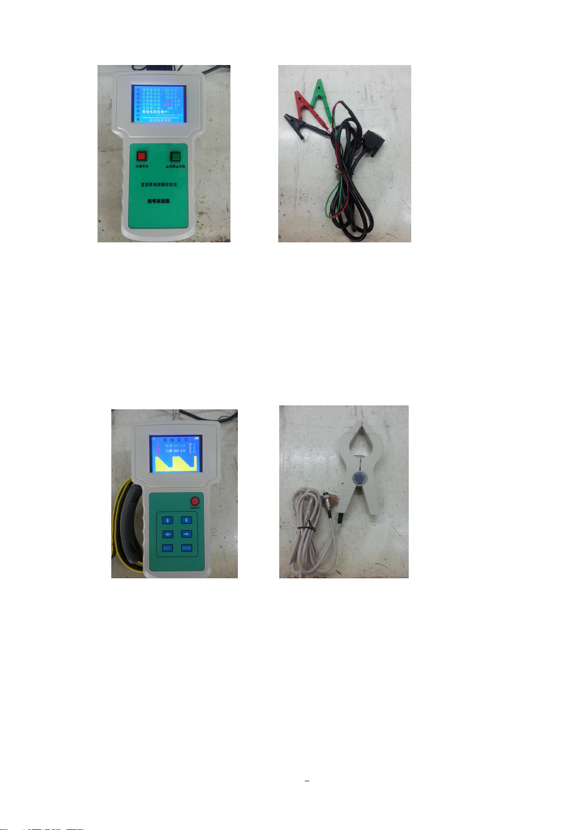
can have a foothold on the market. HZGZ-IV portable DC ground-fault locator
(split type) adopts the technology of sine signal phase advance and data transfer
algorithm. It’s portable and it offers an online performance. The instrument has a
characteristic of high detection sensitivity, strong anti-jamming capability, small
volume, light weight and it’s easy to use. When seeking DC system ground-fault,
you don't need to break the power to locate the grounding point. The instrument
can detect DC system's grounding resistance and its grounding direction, which
makes it a reliable and high accuracy instrument for electric power system's
ground-fault searching and locating.
Part 2. Main features of the instrument
1. The instrument is consist of analyzer and ground-fault locator, the
analyzer (which can be used to detect bus-bar grounding resistance) can access
to the power from bus-bar directly and it doesn't have to access AC power
system or battery, so it’s more convenient.
2. 110V/ 220V DC system share the same DC grounding detector.

2
3. It can completely locate DC system's ground-fault and get rid of the
interference of the large distributed capacitance from the site and also accurately
lock the grounding area in a small range.
4. It applies to grounding caused by the string of AC or DC, ring network
power supply grounding, diode isolated power supply grounding and high
grounding resistance.
5. You can fast and accurately find single point or multipoint of grounding
positions without installment, power break or shake the insulation, the result can
be 100 percent accurate.
6. You can realize automatic detection by just open and close the current
clamp’s jaw opening, the instrument can also prevent misinformation.
7. Luxury outer packing; Easy to carry.
Part 3. Technical parameters
1. Analyzer
working voltage: obtain directly from bus-bar (range from 85V to 260V)
bus-bar grounding resistance’s detection range: 0~500KΩ
bus-bar grounding resistance’s detection accuracy: error ≤10%
power consumption: ≤ 10W
overall dimensions (length × width × height): 238×134×45(mm)
weight: 1.7kg
adaptive temperature: -10℃-+50℃
2. Ground-fault locator

3
working voltage: 12V(lithium battery power supply, 10.8V~12.6V)
by-pass grounding resistance’s detection range: 0-200 KΩ
by-pass grounding resistance’s detection accuracy: error ≤10%
power consumption: less than 1W
overall dimensions (length × width × height): 238×134×45(mm)
weight: 1.5kg
adaptive temperature: -10℃-+50℃
Part 4. Function instructions of different parts of the front
panel and menu introduction
The instrument is consist of analyzer and ground-fault locator
Analyzer Analyzer’s output line

4
Ground-falult locator Locator’s current clamp
(1) Analyzer
Power switch: place the switch on ‘ON’; connect working power supply;
power indicator light lights up.
Bus-bar/ branch: when place the switch on ‘bus-bar’, the instrument detect
bus-bar (it will detect through bridge measurement method); when place the

5
switch on ‘branch’, the instrument will detect branch (bridge measurement
method will not work)
LCD: color screen, resolution (320*240), dynamic display.
(2) Ground-fault locator
1. Power key
2. Operating key: ↑(up), ↓(down), ←(left), →(right), ESC(escape),
ENTER
3. The display: color screen, resolution (320*240), dynamicly display.
(3) Locator’s menu introduction
Main menu
Alarm Threshold
Main Menu
Phonetic Function
Synchronizing Signal
Detection Mode
Display Function
Start Detection
1. Alarm threshold

6
Main menu >> Alarm threshold
Alarm threshold
060KΩ
ESC
ENTER
set branch grounding alarm threshold (default 60KΩ)
2. Phonetic function
Main menu >> Phonetic function
Phonetic function
Main switch on
Boot phonetic on
Synchronizing prompt on
Battery under voltage
Grounding alarm on
Volume level 10
ESC
ENTER
1) Main switch
phonetic main switch (on/off) (default on)
2) Boot phonetic
Will make up later
3) Synchronization prompt
Will make up later

7
4) Battery under voltage
on: phonetic alarm output when battery voltage less than 10.8V
off: buzzer alarm output when battery voltage less than 10.8V
factory setting is on
5) Grounding alarm:
on: phonetic alarm output when grounding resistance less than alarm threshold
off: buzzer alarm output when battery voltage less than alarm threshold
(default on)
6) Volume level
from level 1to level 16 (default level 10)
3. Synchronizing signal
Main menu >> Synchronizing signal
Synchronizing signal function
Synchronizing signal on
ESC
ENTER
on: transmitter and receiver have a synchronization signal (it’s a fixed pattern)
4. Detection method

8
Main menu >> Detection method
Detection method
Auto-detection
ESC
ENTER
auto-detection: means real-time detection, you don't need to press any key
manual-detection: means you should press the ENTER button to start the
detection
(default auto-detection)
5. Display function
Main menu >> Display function
Display function
Test data display off
ESC
ENTER
Detection interface display
Waveform interface
1) Test data’s display
on: display related tested voltages (for debugging)
off: close related tested voltages
this switch only applies to the following 2) common interface
(default off)

9
2) Detection interface display
common interface: display related detection information line by line
waveform interface: display detected information through waveform
(default waveform interface)
6. Start detection
enter the testing interface
Part 5. Interface display introduction
1、Analyzer
1) Bus-bar detection status
When it's ungrounded, it shows as follows.
DC system grounding detection
Bus-bar total voltage: 153.0 V
Positive bus-bar voltage: 64.2 V
Negative bus-bar voltage: 88.8 V
Positive grounding resistance: 999.9 KΩ
Negative grounding resistance: 999.9 KΩ
The value of AC string current: 000 V
No grounding resistance
The positive and negative grounding voltage is
in the second bridge network state.
The instrument is testing the bus-bar.
When grounded, it shows as follows.
DC system grounding detection
Bus-bar total voltage: 153.0 V
Positive bus-bar voltage: 123.6 V
Negative bus-bar voltage: 29.4 V
Positive grounding resistance: 999.9 KΩ
Negative grounding resistance: 48.9 KΩ
The value of AC string current: 000 V
Bus-bar is grounded, please check the by-pass
The positive and negative grounding voltage is
in the first bridge network state.
The instrument is testing the bus-bar.

10
By-pass detection status
DC system grounding detection
Bus-bar total voltage: 154.2 V
Positive bus-bar voltage: 124.6 V
Negative bus-bar voltage: 29.5 V
Positive grounding resistance: 999.9 KΩ
Negative grounding resistance: 47.1 KΩ
The value of AC string current: 000 V
Stop the detection of bus-bar.
The instrument is testing the by-pass.
2. Ground-fault locator
1) Common interface
Ungrounded
Grounding locating
Grounding resistance: 999 KΩ
Grounding direction: no
Alarm threshold: 060 KΩ
Detection status: complete
Synchronizing signal shaking hands
complete, please keep the status of
transmitter and receiver.
Press ESC to return main menu
Grounded
Grounding locating
Grounding resistance: 053 KΩ
Grounding direction: positive direction
Alarm threshold: 060 KΩ
Detection status: in the test
Synchronizing signal shaking hands
complete, please keep the status of transmitter
and receiver.
Press ESC to return main menu

11
Jaw opening open
Grounding locating
Grounding resistance: KΩ
Grounding direction:
Alarm threshold: 060 KΩ
Detection status: jaw opening open
Synchronizing signal shaking hands
Receiver, please reset ‘by-pass’ status
Press ESC to return main menu
2) Waveform interface
Ungrounded
Ungrounded
Grounding locating
Detecting 999 KΩ
Threshold 060 KΩ
Grounded in the positive direction
Grounded
Grounding locating
Detection 052 KΩ
Threshold 060KΩ
Positive
direction

12
Grounded in the negative direction
Grounded
Grounding locating
Threshold 060KΩ
Detection 050KΩ
Negative
direction
Jaw opening open
Current clamp’s jaw
opening open
Grounding locating
Part 6. Directions for use
1. Make the analyzer’s power switch off, insert output signal line plug into
the socket of analyzer, clip the positive bus-bar (red crocodile clip) of signal
output line on the positive ground of current bus-bar, clip negative bus-bar of
signal output line (black crocodile clip) on negative ground of current bus-bar,
clip ground of signal output line (green crocodile clip) on the iron shell (the
ground) of DC cabinet.
2. Place analyzer's 'bus-bar/by-pass' switch on 'bus-bar', analyzer starts to
detect. If it's grounded, the LCD will show the value of the resistance and

13
display whether it’s positive grounding or negative grounding; If it's ungrounded,
it displays 999.9KΩ.
3. Open up ground-fault locator, LCD will display related parameters. If the
battery voltage is under voltage, it means the instrument's battery has no power
and needs to charge. Connect the charger's AC220V power supply, insert the
charging plug into charging jacks, after 3 hours' chargement the lithium battery
can be used again. This instrument's power is supplied by lithium battery, the
voltage will gradually decline in the process of using. When the voltage gets
down to less than 10.8V, buzzer alarm will output all along, which means the
instrument can not work, at the moment, we need to charge the battery; at the
same time, the interface prompt that 'synchronizing signal is shaking hands'.
Place the transmitter's 'bus-bar/by-pass' switch on 'by-pass', the receiver shows
'Synchronizing signal shake hands successfully; Transmitter, receiver, please
keep current status'. Whichever reboot or change status will makes receiver get
close to transmitter (reset by-pass) so that synchronizing signal shake hands
again.
4. Use the detection probe of ground-fault locator to lock each by-pass of
DC system, the LCD will show the value of the resistance to ground of current
by-pass and we advise each loop should be detected for 2-3 times to get a stable
value.
5. When using the detection probe to seek by-pass ground-fault, you can
lock the two feeder lines (both positive and negative ones) at the same time, by
only once, you can detect if there is ground-fault on this by-pass. You can also

14
detect the two feeder separately in two times. You can lock the positive feeder
firstly, then lock the negative feeder line, vice versa.
6. Find the ground-fault by-pass, you can seek the ground-fault point along
this by-pass line by the direction of grounding. Detection probe move backward
along this by-pass, if the measured resistance's value increase suddenly, the
nearby point before this test point is the ground-fault point (namely the
ground-point locates between these two points).
7. After clearing the fault point, use the analyzer to detect bus-bar insulation
again, make sure that you have cleared the ground point.
8. Cable between detection probe and position indicator is 1.5m, analyzer's
output line is 2.3m. The length of the cable can be added but you also need to
add some special instructions.
Part 7. Attentions and tips during fault detection
1. Make the analyzer clip on the bus-bar, after boot up it will detect whether
it is positive grounding or negative grounding, place 'bus-bar/by-pass' switch on
'by-pass', then you can use the analyzer to seek the fault point along the by-pass
line. If you want to return and check the bus-bar's grounding status, place
'bus-bar/by-pass' switch on 'bus-bar', detect twice to get a stable value.
Special attention: after place 'bus-bar/by-pass' switch on 'by-pass', if
you want to place the switch on 'by-pass' at once after checking bus-bar line
status, the analyzer must restart until it display the value of grounding
resistance, then place the switch on 'by-pass'.

15
2. After finding the grounded by-pass, you need to seek from its sub
by-pass.
3. Clip the current clamp on different point of the line, if you detect
grounding point on point A, but not point B, then the fault point is on the line
between A and B.
Part 8. Matters need attention
1. Before using this instrument, please read our instructions carefully.
2. When using this instrument, if DC system bus-bar already have insulation
monitor, you must turn it off or quit in order to avoid its interference to our
instrument's test.
3. When you find the instrument failure, please contact us in time, we will
offer maintenance and replacement, please do not tear down the instrument
yourself.
Table of contents
Other Huazheng Security Sensor manuals