Huazheng HZJF-9011D User manual

HZJF-9011D
Partial Discharge Detector
User Manual
Huazheng Electric Manufacturing (Baoding) Co., Ltd

Dear use r:
Thank you for choosing HZ JF -9011D Partial Dis charge Det ec tor.
We hope that this instrum ent can mak e your wo rk easier an d mo re
enjoyable, so that yo u can get the feeling of offi ce aut om at ion in the test
and ana ly si s work.
Before using the instrument, please read thi s ma nu al, and opera te and
maintain th e instrum en t according to the manual to prolong its se rvice life.
"Just a lig ht press, the test will be completed au tomatically" is the
operating chara ct eristi cs of this instrument.
If you ar e sat isfied wi th th is inst ru ment, please tell your col leagues;
if you ar e not sati sfied with this instrum en t, please call (0 31 2) 6775656 to
tell you to serve you at all times-Baoding Huazheng Electric Manufact ur ing
Co. , Ltd., our comp an y will def initel y make you sa tisfied !

Contents
I.Overview......................................................................................................................................... 1
II.Main Technical Indicators............................................................................................................1
III.Operating Principle..................................................................................................................... 3
IV.Structure Description..................................................................................................................5
V.HZJF-9011D Description Of Front Panel And Rear Panel Components............................6
VI.Operating Instructions................................................................................................................6
VII.Packing list................................................................................................................................24
VIII.User selected equipment (Optional need extra money)............................................... 24

1
I.Overview
HZJF-9011D partial discharge detector is a new type of digital partial discharge
detector developed by our company. It retains the advantages of JF-A01N partial
discharge detector, reduces the volume and optimizes the performance. It uses 10.1
inch touch screen to replace the traditional operation mode of oscillograph and physical
knob, making it more convenient to use.
The instrument adopts full touch screen operation, which not only improves the
service life of the operation, but also has the following functions: one key automatic
correction; high voltage test voltage divider ratio can be set; serial communication
upload test data. The instrument has the characteristics of high sensitivity, wide
application range, wide dynamic range of amplification system, multiple frequency
band combinations (nine kinds), and strong anti-interference ability. It is a practical
partial discharge testing instrument widely used by electric power departments,
manufacturers and scientific research institutes.
II.Main Technical Indicators
1. The equivalent capacitance ranges from 6pF to 250 μ F
2. Number of channels: single channel
3. Measurement range: 0.1pc-10000nc
4. Detection sensitivity and allowable current (see Table 1)

2
Table 1. Detection sensitivity and allowable current value of input unit
5. Elliptic scan time base
(1) Frequency 50/60, 100, 150, 200, 400Hz
(2) Rotation: 30 ° as the first gear, and can rotate 120 °
(3) Working method: ellipse sine wave straight line
6. Display unit
10.1 inch capacitive touch screen is used.
7. Amplifier
(1) 3dB low frequency fl:10, 20, 40KHz optional
(2) 3dB high frequency fh:80, 200, 300kHz optional
NO.
Tuning
Capacitance
Range
Sensitivity
(PC)
(Unbalance
d Circuit)
Effective Value Of
Allowable Current
Unbalanc
ed Circuit
Balance
Circuit
1
0~25~100pF
0.02
30mA
0.25A
2
25~100~400pF
0.04
50mA
0.5A
3
100~400~1500pF
0.06
120mA
1A
4
400 ~1500 ~
6000pF
0.1
0.25A
2A
5
1500 ~6000 ~
25000pF
0.2
0.5A
4A
6
0.006 ~0.025 ~
0.1μF
0.3
1A
8A
7
0.025~0.1~0.4μF
0.5
2A
15A
8
0.1~0.4~1.5μF
1
4A
30A
9
0.4~1.5~6.0μF
1.5
8A
60A
10
1.5~6.0~25μF
2.5
15A
120A
11
6.0~25~60μF
5
25A
200A
12
25~60~250μF
10
50A
300A
7R
Resistance
0.5
2A
15A

3
(3) Gain adjustment, rough adjustment 6, inter gear gain difference 20 ± 1dB, fine
adjustment range >20db
(4) Asymmetry of positive and negative pulse response <1dB
8. Time window
(1) Window width: adjustable, 5 °~ 170 °at 50Hz
(2) Window position: each window can rotate 0 °~ 170 °
(3) Two time windows can be opened separately or simultaneously.
9. Peak pulse display
The touch screen displays 1 decimal place (10pc or more), 2 decimal places (less than 10pc),
error: ±3% (in full scale)
10. Test voltage display
(1) Range 150kV
(2) Input impedance: >1m Ω
(3) Display: touch screen display, display 1 decimal place
(4) Error: ±1%
11. Test frequency display
Error: less than ±1%
12. Zero standard system
Zero sign is consistent with all ellipse scanning frequencies
13. Structure
(1) Dimensions: 370mm (width), 460mm (depth), 215mm (height)
(2) Weight: about 12.5kg
III.Operating Principle
When the sample CXproduces partial discharge under the test voltage, the pulse
current is generated through the coupling capacitor Ck, and the pulse signal is picked up
by the input unit. After being amplified by low noise preamplifier, filter amplifier and main
amplifier (reaching the required amplitude), the visible discharge pulse is generated on
the elliptical scanning baseline of the touch screen, and the pulse peak value is displayed

4
at the same time. The time window unit selects the working time of the pulse peak meter
in each cycle of the test voltage, and marks the corresponding display area of the touch
screen in red during this working time, which can avoid the interference of fixed phase,
which is a conventional discharge test method.
When using JZF calibration pulse generator to inject the known electric quantity of
sample CX, through automatic correction, the display value of discharge capacity is
consistent with the injected electric quantity, so the discharge quantity of the tested object
can be read out directly on the touch screen during the voltage test without calculation,
which is very convenient.
The working principle of the product can be seen in the block diagram (Figure 1)
Figure 1 HZJF-9011D Block diagram of partial discharge detector

5
IV.Structure Description
The instrument is a desktop standard cabinet structure. The operation surface of the
instrument is divided into two parts: front panel and back panel. The positions of each
component are shown in Fig. 2a and 2b
Figure 2a HZJF-9011D Schematic diagram of front panel of partial discharge detector
Figure 2b HZJF-9011D Schematic diagram of back panel of partial discharge detector

6
V.HZJF-9011D Description Of Front Panel And Rear
Panel Components
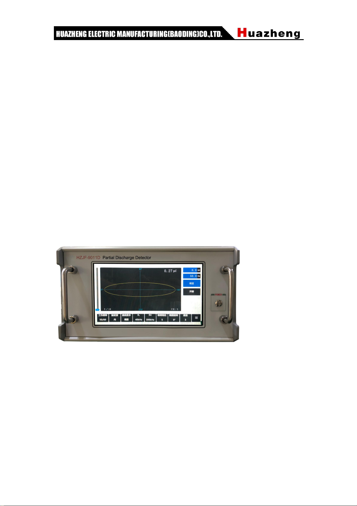
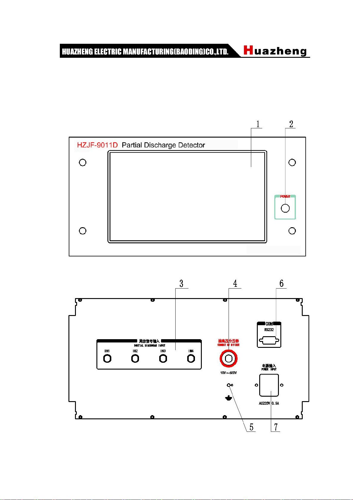
1. Touch screen: display the measured PD waveform, PD, test voltage, test frequency
and other parameters;
2. Power switch button: press once to turn on; press again to turn off;
3. Partial discharge input: partial discharge measurement signal input, HZJF-9011D
single channel, signal can be connected from any channel;
4. High voltage voltage divider, voltage range: 150V;
5. Grounding bolt: reliable grounding is required during test;
6. RS232 port: through this serial port, the parameters of partial discharge instrument can
be uploaded to other equipment;
7. External power supply input;
VI.Operating Instructions
(1)Preparation test
1. Check the grounding condition of the test site. Connect the grounding bolt 5 at the back
of the instrument with the grounding wire of the test site with thick copper wire (preferably
braided copper tape). The grounding short circuit piece of the input unit should also be
properly grounded.
2. According to the size of the test capacitor CX coupling capacitance CK, select the
suitable serial number input unit. In Table 1, the tuning capacitance refers to the
equivalent capacitance seen at the two ends of the primary winding of the input unit
(which can be roughly estimated by the series value of CX and CK).
The input unit should be as close as possible to the tested object. The Q9 socket of the
input unit is connected to the amplifier input socket 3 (channel 1) on the back panel of the
instrument through an 8-meter long cable.
3.There are several methods to connect the sample to the input unit (see Figure 3).

7
Figure 3a Parallel connection
Figure 3b Series connection
Figure 3c Balanced connection
Figure 3d Bridge tapping method

8
In the figure: CX -- sample; CK -- coupling capacitance; Z -- blocking impedance;
R1, C1, R2 and C2 are the balanced regulating impedances.
4. Connect the resistance voltage divider or capacitor voltage divider at the high voltage
end, and connect its output to the input socket 4 of back plate "connected to high voltage
voltage divider" through the measuring cable.
5. The common partial discharge test circuit is shown in Figure 4
Figure 4 Standard connection circuit of partial discharge test (parallel connection of direct
method)
(2)How to use it
Home Screen

9
Windowing interface
Setting interface
Example 1: adjust the working frequency.
Step 1: click the working frequency button.
Step 2: select the corresponding working frequency in the pop-up menu.

10
Example 2: select the curve display mode.
Step 1: click the curve display button.
Step 2: select the corresponding display mode in the pop-up menu.
Example 3: setting coarse adjustment gear.
Step 1: click the coarse adjustment gear button.
Step 2: select the corresponding gear in the pop-up menu.

11
Example 4: select signal channel.
Step 1: click the channel button.
Step 2: select the corresponding channel in the pop-up menu.
Example 5: window operation.
Step 1: click the window opening button to enable the window opening function.
Step 2: click the window mode button to select the corresponding selection mode.
Step 3: adjust the corresponding window opening area through the window position slider
and window length slider.

12
Example 6: setting interface operation.
Step 1: click the setting button to switch to the setting interface.
Step 2: click the value box to be set and the keyboard input window will pop up.
Step 3: after inputting the corresponding value in the keyboard window, click the input
completion button.
1. Start up preparation
Connect the power socket 7 with the 220 V power frequency power supply, press the
power switch 2 to start the machine, select "50 / 60" in the "working frequency" button

13
menu and "ellipse" in the display mode button menu. Confirm the set PD calibration
target value (factory default 50pc).
2. Instrument calibration
Refer to figure 4, connect the wire and calibrate it with JZF calibration pulse generator
before adding test voltage.
Note: the lead wire on the red terminal of the calibration pulse generator shall be as short
as possible and connected to the high-voltage end of the test object, and the black
terminal wire shall be connected to the low-voltage end of the test object.
Press the high frequency button "FH" and the low frequency button "FL" to select the
appropriate frequency bandwidth.
Press the "coarse adjustment" button, select the automatic gear, and then press the
"correction" button; the discharge quantity indication is consistent with the known electric
quantity injected.
After the calibration is completed and before the test voltage is applied, the connection
line between the calibration pulse generator and the test object must be disconnected to
prevent the high voltage from damaging the calibration pulse generator.
3. Test operation
Turn on the power supply of high-voltage test circuit, slowly increase the test voltage,
press the "ellipse rotation" button, select the rotation angle, and make the ellipse turn to
the expected place which is most convenient for observation during discharge. Usually,
this position is the place where the zero mark pulse is located on the left side of the upper
part of the ellipse and the right side of the lower part respectively. When the voltage is
increased continuously, pay attention to the first continuous discharge. When the
discharge exceeds the specified minimum value, the voltage is the starting voltage of
partial discharge.
Various interferences are often found in the test. The width and position of the red area
on the ellipse can be changed by "windowing mode", "windowing position" and
"windowing length" to avoid the interference pulse.

14
4. Partial discharge test with frequency higher than 50 Hz
When partial discharge test higher than 50 Hz is required, press the "working frequency"
button to select the corresponding frequency range, and take 10v-250v test voltage from
high frequency test power supply and send it to socket 4.
(3)Supplementary Provisions
1. Identification of discharge type and discharge source
Firstly, the ellipse track on the oscillograph screen is introduced. It rotates clockwise. The
positive zero mark pulse indicates that the test voltage begins to change from negative to
positive; on the contrary, the midpoint between the two zero standards is the positive and
negative peak positions of the test voltage.
It is a highly technical and practical knowledge to identify discharge types and various
interferences from discharge patterns on ellipses (it is better to combine with other
methods to confirm). CIGRE (International Conference on large power grid) has also
compiled a pamphlet for recognizing the discharge pattern. It is judged according to the
discharge position and movement in the discharge pattern, the consistent degree of
discharge amplitude in positive and negative half cycle, and the variation characteristics
of discharge amplitude with test voltage and pressurization time, which can only be
roughly introduced here.
Generally speaking, the main characteristic of partial discharge, which is regarded as the
formation of real internal bubble, is that most of the partial discharge occurs within two
and a half weeks near the rising position of the test voltage peak.
(1) Typical internal bubble partial discharge (see Figure 5), waveform characteristics: a
discharge is mainly shown in the test voltage from zero to peak within two elliptical phase
limits. B when the initial voltage UI, the discharge usually occurs near the peak value.
When the test voltage exceeds UI, the discharge extends to the zero position. C the
discharge times and amplitudes of the two opposite half cycles are approximately the
same (the maximum difference is 3:1). The discharge waveform can be distinguished.
There are several situations: 1) if the discharge amplitude increases with the increase of

15
test voltage, and the discharge waveform becomes indistinct, it is often that there are
many bubbles in the dielectric or discharge on the surface of the dielectric; 2) in addition
to the above conditions, if the discharge amplitude increases rapidly with the pressure
time (up to 100 times or more), it is often the bubble in the insulating liquid Discharge, a
typical example is the discharge of oil impregnated paper capacitor.
Figure 5
(2) For the discharge of bubbles between metal and dielectric (see Fig. 6a), the waveform
characteristics are as follows: there are many discharges with small amplitude in the
positive half cycle and a few discharges with large amplitude in the negative half cycle,
and the amplitude difference can reach 10:1. Others are the same as above. A typical
example is the discharge of polyethylene cable with poor adhesion between insulation
and conductor. If the discharge amplitude increases with the increase of the test voltage,
and the discharge waveform becomes fuzzy, it often contains multiple bubbles of different
sizes, or the discharge occurs between the exposed metal and the dielectric surface (see
Fig. 6b).
Fig 6a Fig 6b
Some cases which are mainly considered as interference or abnormal discharge are

16
discussed below.
(3)Suspended potential object discharge (see Fig. 7a), waveform characteristics: it
appears in two quadrants of positive and negative half cycle before the voltage peak, the
amplitude, pulse number and position are the same, sometimes (as shown in Fig. 7b)
appear in pairs, the discharge can move, but the mutual interval between them remains
unchanged, when the voltage increases, the number of elements increases, the interval
decreases, but the amplitude remains unchanged, and sometimes the voltage rises to a
certain value Will disappear, but will reappear at this value. Cause: discharge caused by
the gap between metals. The gap may be between two independent metal bodies on the
ground or in the sample, such as loose shielding.
Fig. 7a Fig. 7b
(4) External tip corona (see Figure 8a), waveform characteristics: the initial discharge
only occurs in one and a half cycles of the test voltage, and is symmetrically distributed
on both sides of the peak value. When the test voltage increases, the number of
discharge pulses increases sharply, but the amplitude remains unchanged and extends
to both sides (as shown in Fig. 8b). Cause: high voltage tip or edge discharge in air. If the
discharge occurs in the negative half cycle, it indicates that the tip is at high voltage; if the
discharge occurs in the positive half cycle, the tip is at the ground potential.
1.

17
Fig. 8a Fig. 8b
(5) Tip corona in liquid medium (Fig. 9a), waveform characteristics: discharge occurs in
two and a half cycles, symmetrically distributed in two voltage peaks. Each group of
discharge is equal interval, but a group of larger amplitude discharge appears first, and
increases with the increase of test voltage, not necessarily equal amplitude: a group of
small amplitude discharge amplitude is equal, and does not change with voltage (as
shown in Fig. 9b). Cause: the tip or edge discharge in insulating liquid, if a group of large
discharge occurs in positive half cycle, the tip is at high voltage; if it appears in negative
half cycle, the tip is at ground potential.
Fig. 9a Fig. 9b
(6) Poor contact (FIG. 10), waveform characteristics: symmetrically distributed on both
sides of the zero point of the test voltage, the amplitude is roughly unchanged, but it
drops to zero near the peak value of the test voltage, and the waveform is rough and
unclear. When the voltage increases, the amplitude increases slowly, and sometimes it
disappears completely when the voltage reaches a certain value. Causes: the connection
point of metal to metal poor contact in the test circuit; the poor contact of semiconductor
particles in the shielding layer of plastic cable; the plug piece of aluminum foil of capacitor,
etc. (the capacitor can be charged and then short circuited to eliminate).
Table of contents
Other Huazheng Security Sensor manuals
Popular Security Sensor manuals by other brands

Pfeiffer Vacuum
Pfeiffer Vacuum ASM 390 operating instructions

Millenium
Millenium Ol'Man O-030-00 instruction manual

BEA
BEA SBK-30R user guide

PCB Piezotronics
PCB Piezotronics 8120F-410A Installation and operating manual

AVIRE
AVIRE ESD installation guide

Floodstop
Floodstop FS34NPT Installation and operating manual