Huazheng HZ-5000 User manual

HZ-5000 Underground Cable
Detector
User Manual
Huazheng Electric Manufacturing (Baoding) Co., Ltd

Dear use r:
Thank you for choosing HZ-50 00 Underground Cable Fault De tector.
We hope that this instrum ent can mak e your wo rk easier and mo re
enjoyable, so that you can get the feel in g of office automat io n in th e test
and an al ysis wo rk.
Be fore using th e instrum en t, please rea d this manual, and ope rate and
maintain the instrum ent accordi ng to the manual to pr olong its servi ce life .
"Just a lig ht pr es s, the tes t will be co mp le ted au tomatically" is th e
oper at ing cha racteristics of thi s instrument.
If you ar e sat is fied wi th this instrum ent, ple as e tell your colleagues;
if you are not sat is fied wi th this inst rume nt, ple ase call (0312) 6775656 to
te ll you to serve yo u at all times-Bao di ng Huazheng El ec tric Man ufacturing
Co. , Lt d., our company will de finite ly make you satisfied !

1
Contents
I.Overview......................................................................................................................................... 2
II.Features ofHZ-5000 Cable Fault Detector.............................................................................. 2
III.Components and structural functions ofHZ-5000 cable fault detector.............................. 4
IV. Specifications............................................................................................................................19
V. Parts and Accessories..............................................................................................................20
VI. Check before use.................................................................................................................... 20
VII. Ways of Pipe locating:........................................................................................................... 23
VIII. Procedures of Detection.......................................................................................................41
IX.Common Pipe Detection Techniques.................................................................................... 44
X.Anti Corrosion Coating Inspection.......................................................................................... 49
XI.Cable low resistance and broken line fault points...............................................................52

2
I.Overview
TheHZ-5000 underground cable fault detector can accurately locate and measure the
buried depth of underground pipelines, cables, and optical cables without excavation, and
accurately find the location of the damaged point of the outer anti-corrosion layer of the
underground pipeline and the fault point of the buried cable. The instrument integrates
the most advanced technologies such as ultra-narrowband filter, Bluetooth wireless
communication, GPS positioning, professional data analysis software automatic mapping,
automatic generation of test reports, etc. It has super anti-interference ability, precise
positioning and depth sounding, and is suitable for various underground The detection
and inspection of metal pipelines, pipeline management and maintenance, municipal
planning and construction, power supply and other departments are the necessary
instruments for pipeline maintenance units.
II.Features of HZ-5000 Cable Fault Detector
1. Multiple Functions
1) Transmitter: three connection modes: inductive connection, direct connection and
clamp connection; suitable for different occasions.
2) The receiver functions: detecting the position,path, depth and tube current of
underground pipes and cables.
3) Left and right positioning arrows indicate the target pipeline position fast and
accurately; front and rear arrows and dB value indicates the point and size of the coating
damage.
4) Backlight suitable for urgent use in the nighttime.
5) Optional GPS geolocation with the automatic mapping of the pipelines.
6) Optional professional data analysis software with the automatic detection report.

3
7) Specific functions ofHZ-5000 receiver: Used for locating faults (pipeline faults refer to
damage of outer anticorruption layer, cable faults refer to damage of outer sheath) and
detecting insulation damage of underground pipelines.
8) Measuring the current of the pipeline and cable applied by the transmitter.
9) Multimeter function: measure the output voltage, line voltage, line current, impedance
and power; Test the cable continuity and insulation quality before and after cable fault
finding.
10) External induction clamp: suitable for testing the cable when they cannot be directly
applied to the signal of the place.
2. High Location Accuracy
A variety of measurement modes for pipeline positioning (valley mode, peak mode, broad peak
mode, peak arrow mode), can verify each other to ensure the accuracy of pipeline positioning.
1) Maximum value method: peak mode, broad peak mode and peak arrow mode are available
to determine the horizontal component ( ) or horizontal gradient ( ) changes,
according to its maximum position to locate;
2) Minimum value method: use the valley mode by measuring the vertical component ( )
changes according to its minimum position to locate.
3. Measuring the depth
A variety of methods can be used to verify each other.
1) double-level coil direct reading method;
2) single-level coil 80% method, 50% method;
3) 45 degrees method
4. Strong anti-interference ability
1) Many Observation Parameters: can measure horizontal component ( ), vertical
component ( ) and horizontal gradient ( ).
2) Large transmission power: the transmitter output power reaches 10W and it could be
continuously adjustable.

4
3) Multiple Working Frequency:
Transmitter frequency: 128Hz, 512Hz, 1KHz, 2KHz, 8KHz, 33KHz, 65KHz, 83KHz.
Receiver frequency: radio, 50Hz, 100Hz, 128Hz, 512Hz, 1KHz, 2KHz, 8KHz, 33KHz,
65KHz, 83KHz.
According to the target pipeline features (material, structure, depth, length, etc.) and the
environment to select the appropriate operating frequency.
5. Easy Operation
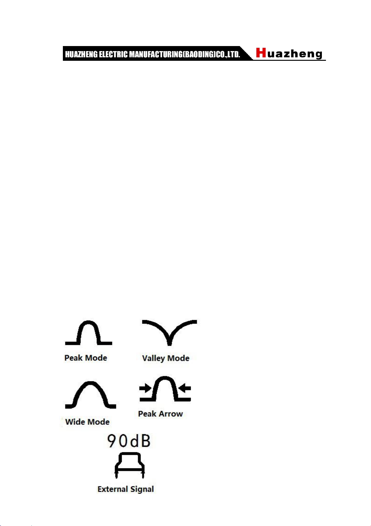
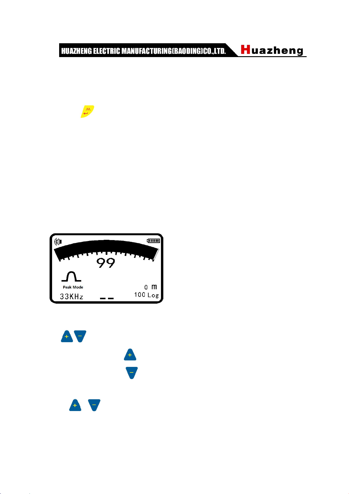
1) Intuitive: use the graphical display to get the sustained and real-time display of various
parameters in the detection process and signal strength.
2) Automatic: in the depth measurement, automatic change to the two-level antenna
mode and automatic adjustment of the receiver sensitivity so that the measurement
signal achieves the best result. The mode returns to the original one after the depth
measurement.
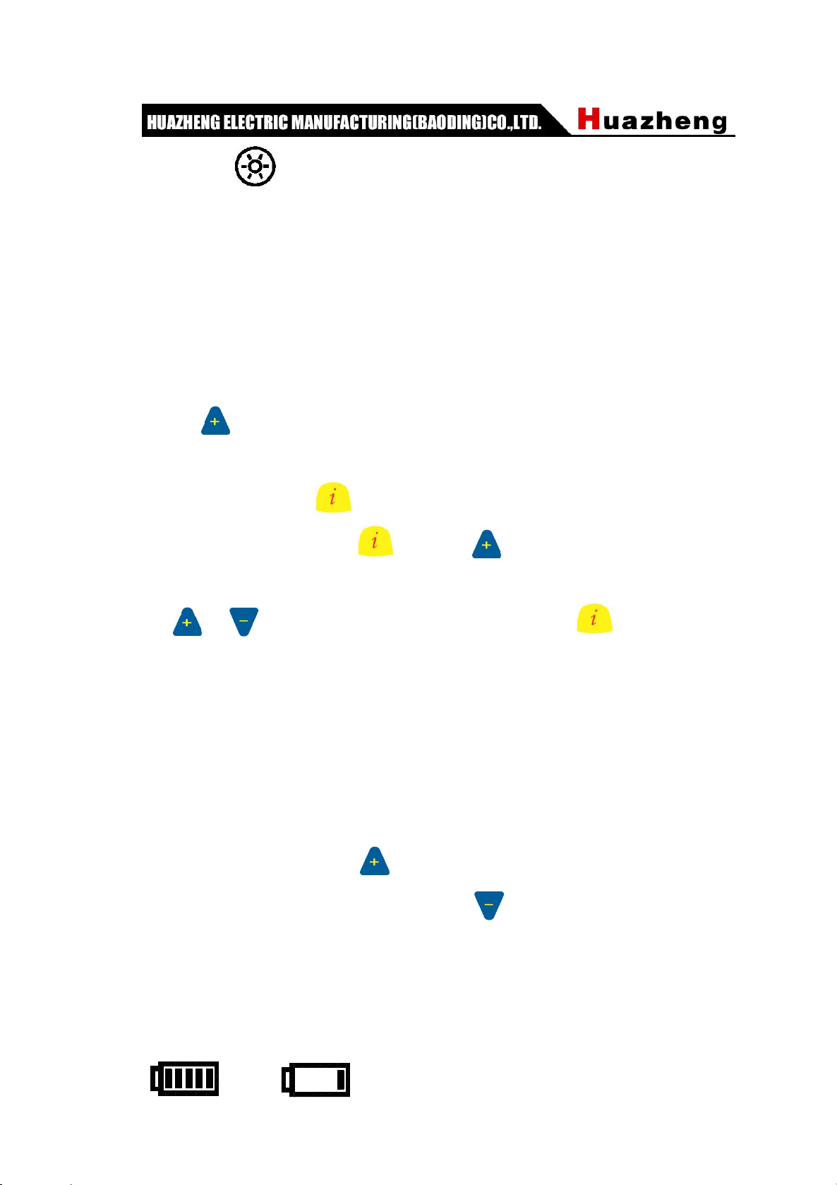
6. Long continuous working time with the low cost
Both the transmitter and the receiver are equipped with a large capacity lithium battery
pack. A fully recharge can last a whole working day outdoors. The recharging function has
greatly reduced the detection costs.
7.AC and DC
Under normal circumstances, if the battery is sufficient, please use the instrument
with built-in battery pack power supply. If the battery power is low, and the detection task
is not completed, you can use the power adapter to continue the detection without having
to recharge the battery.
III.Components and structural functions ofHZ-5000
cable fault detector
1. Receiver:

5
The receiver is used for the measurement of underground pipelines, cable positioning,
buried depth of underground pipelines, and tube current measurements. A variety of
frequency and mode of operation to meet a variety of environments and a variety of
pipeline detection needs.
1.1 Functions:
Turn on/off (1)
Press the key to start the boot or to shut down. When the receiver is turned on, the
receiver automatically shuts down if no function key is pressed during the set auto power
off time. If any function key is pressed, the receiver will reset the shutdown time.
fbutton(2)
Frequency selection key: according to the frequency of the transmitter to select the
corresponding detection frequency, selectable frequency including radio, 50Hz、100Hz、
128Hz、512Hz、1KHz、2KHz、8KHz、33KHz、65KHz、83KHz.

6
Mode(3)
The mode key is used to select the receiver's operating mode for precise positioning of
the pipeline. The positioning process is usually measured by the peak method.
Including:
Valley mode
Peak mode
Wide mode
Peak arrow mode
Power mode: 50Hz power cable can be detected
When there is an external A-frame, you can also select the external signal mode.
(4)
To increase, please press
To decrease, please press .
In the adjustment, the number is shown in the middle of the display window.
Press or for 3 seconds to start the function automatically. The number turns into
flashing cursor(as shown on the left), the instrument automatically adjusts the Signal
strength to about 70% of full scale. The relative intensity of the signal is indicated by the

7
bar graph(8) above the display window and the number(9) below the graph.
Depth/Current(5)
key is used to measure the depth of the buried pipeline, meanwhile it could
measurethe current value in the target line. In the current measurement process,
regardless of the original use of which positioning mode, the system automatically
switches to the peak mode.
The depth measurement unit can be selected by metric or imperial from the menu.
Metric Units: cm when the depth of the pipeline is less than 1 meter.
When the depth is more than 1 meter, the depth display unit is m.
Inch unit: feet.
Current unit: When the current is more than 1A, the display current unit is A, when the
current is less than 1A, the display current unit is mA.
Note:
1, in order to measure the exact depth of the depth, the receiver must be
maintained in the vertical position of the work.
2, in order to improve the accuracy of the depth of the measurement, it is not
suggested to use the valley mode, the wide-peak mode is recommended for
pipeline depth measurement.

8
Backlight(6)
Press the backlight key, the backlight of display will turn on and keep a preset time, and
then press the backlight button, backlight is off.
The backlight time can be set via the backlight menu.
Data Storage:
Measured current and depth data storage method: After measuring the current value,
the depth and current value are indicated in the middle of display. If you need to store
data, press button,the detection value is stored in the instrument's memory, and the
lower right corner of the display indicates how much serial number (12) is stored. If
storage is not needed, press button to restore the locating mode.
Browsing Data:After pressing button and button togethrt for 3 seconds,
it enters the interface including frequency, serial number, distance, depth and current, etc.
Press and button to visit the previous and next page. Press again to exit. If
no key is pressed for 20 seconds, it restores the locating mode.
Note: Only 1000 data of the same frequency can be saved. After switching to the
different detection frequencies, if you need to store the data, you must delete the data of
the original frequencies that have been stored before storing the new frequency data.
For example: the instrument has been stored 128Hz data group 100, now it is
changed to the measurement frequency of 512Hz and needs to store 512Hz data to
complete the measurement.,Press to store,Reminder: "128Hz has been stored 100
data, whether to delete", if you need to delete , press for 5 seconds to delete to store
512HZ data.
1.2 Receiver Display

9
Battery Indicators (7)
The upper right corner of the display has a battery symbol that indicates how much
battery power is. When a flashing battery symbol is displayed indicating that the built-in
battery of the instrument is not enough for work and needs to be recharged. Generally,
the machine usesa high-performance lithium battery pack, fully recharged for the receiver
to work more than 10 hours.
Receiver recharging: The charger's circular is connected to the receiver's charging jack,
the other end is plugged into the 110V/220V power supply, charger indicator light is red
during charging, and it will turn green after full charged.
Signal Strength(8、9)
The bar graph above the display window indicates the relative strength of the signal.
The number indicates the signal strength and it can be adjusted by pressing .
Display the lower side of the window with the number 0-100 to show the receiver's gain
size. When the signal source is strong, it is necessary to decrease. When the signal
source is weak, it needs to increase. When in the normal detection, it is necessary to
adjust the signal strength to about 70% of the full scale.
Display(10)
Display a variety of measurement parameters and measurement results show.

10
Point distance indication(11)
When the GPS is successfully connected and the satellite signal is received, the
detection data saves the distance between the two measuring points and displays it in
real time. If the GPS module is not configured and poi nt distance will display 0m.
Data Storage Log(12)
Once the measured data is stored, the number will be automatically incremented by 1.
100 Log means that 100 groups of data has been saved and it could store 0-1000 data.
Speaker Indicator(13)
The loudspeaker indicator indicates the level of the speaker sound, the sound mode
has high, medium, low and off. When the speaker sound is off, the speaker indicator is
not displayed. The speaker volume is set in the menu settings。
Locating Mode(14)
Press button to select modes(Valley mode, peak mode, broad peak mode and peak
arrow mode),and the mode is displayed.
Frequency Indicator(15)
Use the frequency key to select the desired detection frequency and the frequency will be
displayed.
Increase/Decrease Indicator(16)
The number 0-100 in the lower side of the display shows the receiver's gain size. When
the signal source is too strong, it is necessary to decrease. When the signal source is too
weak, it needs to increase. During the detection, it is necessary to adjust the signal
strength to about 70% of the full scale.
Left/Right Arrow Indicator
When using the valley mode or the peak arrow mode to detect the pipeline position, the
left and right arrows could help to trace the pipeline position quickly. When the instrument
deviates from the left side of the pipeline, the right arrow appears. When the instrument

11
deviates from the right side of the pipeline, the left arrow appears.
Coating Leaking Point Indicator
When testing damage points or cable failure points, the arrows will help to indicate
the location of the position on coating (as shown below). When the forward arrow
appears, the point of failure is in front of the A-frame. When the rear arrow appears, the
point of failure is behind the A-frame.
A frame access status
If A frame is connected, press button to select the external signal mode. A frame is
used to detect the damage point of the coating and shows the size of the damage point in
dB.
Other Locating Method:
50Hz for power line signal detection, CPS signal (cathodic protection current signal), and
radio signal detection.

12
1.3 Receiver Setting
Press key for 3 seconds to enter the main menu. Press or to move
the cursor. Press to enter the submenu or change the setting. Press to return
the main menu.
Menu 1
Language Chinese
Contrast control Entry
British—Metric meter
Speaker Volume Low
English Menu 1
Menu 2
Backlight 15S
Automatic Shut 10min
Bluetooth Pairing Entry
Search For Bluetooth Using
English Menu 2
Language Setting:Move the cursor to Language and Press to change the
language between Chinese and English.
Contrast Control: Move to Contrast Control and press to adjust the
contrast by pressing or . Press to return the main menu.

13
Contrast Control
Measurement Unit Setting:Press to move the cursor to British-Metric setting
and press to set Footage or Metric.
Menu 1
Language Chinese
Contrast control Entry
British—Metric meter
Speaker Volume Low
Menu 1
Language Chinese
Contrast control Entry
British—Metric Feet
Speaker Volume Low
Speaker Setting:Press to move the cursor to Speaker volume setting. Press
to set the volume.

14
Menu 1
Language Chinese
Contrast control Entry
British—Metric Feet
Speaker Volume Low
Backlighting Setting:Press to move the cursor to the backlight time setting.
Press to set the time :5S→15S→30S→1m→oftenlighting→Off→5S。
Menu 2
Backlight 15S
Automatic Shut 10min
Bluetooth Pairing Entry
Search For Bluetooth Using
Automatic Off Setting:Press to move the cursor to automatic off setting.
Press to set the time:30 minutes→10 minutes→ 5 minutes→Never→30 minutes.
Menu 2
Backlight 15S
Automatic Shut 10min
Bluetooth Pairing Entry
Search For Bluetooth Using

15
Bluetooth:Press to move the cursor to set the Bluetooth paring. Press to
enter the Bluetooth pairing.
Menu 2
Backlight 15S
Automatic Shut 10min
Bluetooth Pairing Entry
Search For Bluetooth Using
Bluetooth Pairing
Searching……
Bluetooth Pairing:Press to move the cursor to “HOLUX_M-1200”,
Press to confirm. Receiver is paired with GPS Bluetooth module and the icon in the
display is lighted. The receiver can receive GPS data by the Bluetooth. Press to
return to the main menu.
Bluetooth Pairing
Nokia N70
TOK
HOLUX_M-1200
If there is no Bluetooth searched, it will display NO Bluetooth Equipment Available and
press to return to the main menu.

16
Bluetooth Pairing
Without Bluetooth equipment available
Bluetooth ON:Press to move the cursor to Search for Bluetooth menu.
Press to turn on/off the Bluetooth. (HZ-4000B is not equipped with GPS Bluetooth
and the setting is forbidden.)
Menu 2
Backlight 15S
Automatic Shut 10min
Bluetooth Pairing Entry
Search For Bluetooth Using
Menu 2
Backlight 15S
Automatic Shut 10min
Bluetooth Pairing Entry
Search For Bluetooth Forbidden
2.HZ-5000:Transmitter
The transmitter is adapted to apply a signal of the selected particular
frequency to the target line, and the signal can be applied by the direct connection

17
method and the inductive method. Transmitter with power, measuring distance,
automatic impedance matching, automatic measurement of pipeline grounding
resistance and so on
Front Panel:7 touch keys, 2 indicator lights and a LED display screen.
2.1 Keyboards:
ON/OFF: To turn on/off the transmitter
Frequency: to adjust the transmitter power.
Front Panel
1&2.ON/OFF; 3.Charging Indicator; 4.Voltage Indicator; 5.Working Indicator;
6&7.Frequency Adjustment;
8. Frequency; 9. OK/Enter; 10. Measurement; 11.Working Frequency Indicator;
12.Transmitter Output Parameter; 13. Two frequencies of coating leak detector
Frequency (f): Select the frequency128Hz, 512Hz, 1KHz, 2KHz, 8KHz, 33KHz, 65KHz,

18
83KHz.
Measurement (i): Press the measurement key to select the output parameters of the
instrument:output power percentage, output power, output voltage, output current, output
impedance.
Enter (OK): When you set the frequency to be applied, press the OK key again to change
the transmitter output frequency immediately. If the key is not pressed after the frequency
selection, wait for 5 seconds. The instrument automatically confirms the selected
frequency.
Display
Working Frequency:When the frequency of the transmitter is selected, the corresponding
triangular indicator light is on, and the available frequencies are 128Hz, 512Hz, 1KHz,
2KHz, 8KHz, 33KHz, 65KHz, 83KHz.
Voltage: The bottom line of the display shows the level of the supply voltage. When the
triangular indicator corresponding to the supply voltage is on, it indicates the level of the
power supply. When the supply voltage drops below 11.5 volts, the battery must be
charged.
Output Parameter: The top line of the display shows the output parameters of the
transmitter. The first indicator indicates the percentage of the output power in inductive
mode. The second indicator indicates the output power.The third indicator indicates the
output voltage. The fourth indicator indicates the output current, and the fourth indicator
indicates the output impedance.
Ω
mA
V
W
2KHz
1KHz
512Hz
128Hz 8KHz
33KHz
65KHz
83KHz
%
Table of contents
Other Huazheng Security Sensor manuals