manuals.online logo
Brands
  1. Home
  2. •
  3. Brands
  4. •
  5. HUBBELL LIGHTING
  6. •
  7. Lighting Equipment
  8. •
  9. HUBBELL LIGHTING DUAL LITE EZ-2 Series Manual

HUBBELL LIGHTING DUAL LITE EZ-2 Series Manual

Service / Maintenance
Maintenance
This emergency lighting unit should be tested and maintained in accordance with National Electrical Code and NFPA 101 Life Safety
Code requirements. It is recommended that emergency light fixtures be tested for 30 seconds once a month and for 90 minutes once a
year.
Taking A Unit Out Of Service
If a unit is to be deliberately taken out of service for an extended period, the battery lead connector should be disconnected from
the charger circuit board and insulated so that the battery will go into storage in a fully charged condition.
Replacing the Battery
1. De-energize the AC power.
2. Disengage the Battery cover.
3. Disconnect the battery leads.
4. Remove the battery from the clips inside the cover.
5. Replace with a new battery (see unit model label for correct part number) and reconnect leads.
6. Reassemble battery cover.
Replacing LED Lamps
The LED lamps inside the unit are not replaceable or field serviceable. Please see dual-lite.com for further assistance.
Troubleshooting
Emergency circuit does not work
•Batteries are shipped uncharged and disconnected. Connect battery leads and charge 24 hours before testing.
•Make sure the charger board and test button/light pipe are properly seated and aligned.
•Check wiring connections.
EZ-2 Series
Twin-Head LED Emergency Lighting Unit Standard,
and Spectron® Equipped Models Installation,
Operation, and Service Instructions
WARNING –This product contains chemicals known to the State of California to
cause cancer, birth defects and/or other reproductive harm. Thoroughly wash
hands after installing, handling, cleaning, or otherwise touching this product.
Emergency Lighting Equipment for Use in Damp Locations
Damp location listed units are suitable for installation in:
1. Interior locations subject to moderate degrees of moisture, such as some basements, some
barns, some cold storage warehouses, and the like.
2. Partially protected locations under canopies, marquees, roofed open porches and the like.
IMPORTANT SAFEGUARDS
When using electrical equipment, basic safety precautions should
always be followed including the following.
READ AND FOLLOW ALL SAFETY
INSTRUCTIONS
1. Do not use outdoors.
2. Do not let power supply cords touch hot surfaces.
3. Do not mount near gas or electric heaters.
4. Equipment should be mounted in locations and at heights where it will not
readily be subject to tampering by unauthorized personnel.
5. The use of accessory equipment not authorized by the
manufacturer may cause an unsafe condition.
6. Do not use this equipment for other than its intended purpose.
7. Servicing of this equipment should be performed by qualified service personnel.
8. Test cycling: the Life Safety Code (NFPA 101) requires testing of emergency lighting units once
a month for a minimum of 30 seconds, and once a year for a minimum of 90 minutes.
INSTALLER:
•SEE UNIT LABEL FOR ADDITIONAL MODEL SPECIFICATIONS
•SAVE THESE INSTRUCTIONS FOR USE BY OWNER/OCCUPANT
INSTALLATION
Installing the Unit: Final Assembly
1. Align housing slots over tabs on backplate.
2. Pivot housing and snap closed.
3. Aim the lamps. Do not press on the lenses.
RECYCLING INFORMATION
All steel, aluminum and thermoplastic parts are recyclable.
NOTICE: Emergency units contain rechargeable batteries which
must be recycled or disposed of properly.
Hubbell Lighting, Inc. Life Safety Products •www.dual-lite.com
Copyright
©
Hubbell Lighting, Inc., All Rights Reserved •Specifications subject to change without notice. •Printed in U.S.A.
INSTALLATION
This unit is designed to be mounted on a wall or ceiling. Provide standard units with a single unswitched supply from a 120VAC, 240VAC,
or 277VAC branch circuit used for normal lighting in the area to be protected. For Spectron® self-testing/self-diagnostic units, provide unit
with a 120VAC or 277VAC branch circuit.
The EZ-2 unit is equipped with intelligent wiring. Connect the black wire from the unit to the
hot building wire (120-277VAC) and the white wire to the neutral building wire.
INSTALLATION
**
Once the EZ-2 model is installed, press and hold the test button
**
for more than 5 seconds to initiate the load learn process.
Operation
“AC ON” LED is illuminated when AC power is present.
NOTE: All models are supplied with an AC Lockout circuit, which prevents the emergency lights
from illuminating when the battery is connected, and no AC power is present.
NOTE: All models are supplied with a Low Voltage Disconnect
circuit, which
prevents
damage to
the battery from deep discharge during prolonged emergency operation.
NOTE: Batteries are often shipped in a discharged state –this is normal. The battery will require
charging. Allow 24 hours of charging before testing the unit.
Models with SPECTRON® Self-Testing/Self-Diagnostic Circuitry
Models equipped with the Spectron® self-testing/self-diagnostic electronics system provide:
✓
Visual indication of AC power status
✓
Visual indication of self-diagnostic test status and results
Visual indication of any unit malfunctions includes:
✓
Battery Disconnected
✓
Battery Fault
✓
Charger Fault
✓
LED Driver Fault
✓
Lamp Fault
Spectron equipped units also include:
Brownout protection: unit will automatically transfer to emergency operation upon detection of low AC power
(approximately 80% of nominal line).
Time Delay Retransfer: upon return of normal AC power, unit will remain in emergency mode for an additional 15
minutes to allow AC power to stabilize.
A bicolor LED (green/red) is provided on the control
panel of all models equipped with the Spectron® option.
Green Operating Status LED:
The green Operating Status LED serves as both an AC
power and self-test indicator. During normal operation,
the green Operating Status LED will be illuminated,
indicating the presence of AC power. During all auto-
matic or manual self-test cycles, the green Operating
Status LED will blink twice every second.
Red Service Alert LED:
Under normal operating conditions, the red Service Alert
LED indicator will remain off. If the Spectron® controller
detects a malfunction, the red Service Alert LED will blink
in the pattern listed in the following table:
Red Status LED Code
Description
One blink ON/pause
Battery disconnected
Two blinks ON/pause
Battery fault
Three blinks ON/pause
Charger fault
Four blinks ON/pause
LED Driver fault
Five blinks ON/pause
Lamp fault
Red/Green alternating
Load Learn in Process
Automatic Tests
The unit will automatically initiate a self-test/self-
diagnostic cycle based on the following table:
Testing Period
Duration of Test
once a month
1 minute
Once every 6
Alternating:
months
30 minutes or 60 minutes
Manual Tests
Using the unit test switch, users can initiate different
duration test cycles based on the following table:
Initiating Action
Test Cycle
Press test switch once
1 minute
Press test switch twice
90 minutes
Pressing the test switch any time after a 90 min. test
cycle has begun cancels the remainder of the 90 min.
test and returns the unit to normal operation.
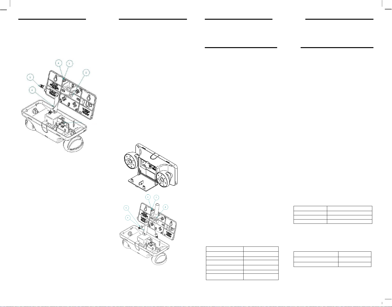
Wall or Ceiling Mount –Back Power Feed
1.
Remove appropriate KO’s in backplate to mount
backplate to junction box.
2.
Remove center KO from backplate and feed supply
leads through.
3.
Secure backplate to junction box.
4.
To help with wiring, attach cover to backplate with
provided plastic hinge.
5.
Connect wires from the unit to the building leads and
6.
secure with wire nuts.
Disengage the battery cover.
7.
Connect battery lead to circuit board header as
shown.
8.
Installer should now become familiar with the
Lamp head aimability and its limitations.
Wall Mount –Surface Wiring (Top Power Feed Only)
1.
Remove appropriate KO’s in backplate and
mount backplate to wall.
2.
Feed wires through and secure conduit to
backplate.
3.
Remove the breakout on top of the housing.
4.
To help with wiring, attach cover to backplate
with provided plastic hinge.
5.
Connect wires from the unit to the building
6.
leads and secure with wire nuts.
Disengage the battery cover.
7.
Connect battery lead to circuit board header as
shown.
8.
Installer should now become familiar with the
Lamp head aimability and its limitations.

This manual suits for next models

11

Other HUBBELL LIGHTING Lighting Equipment manuals

HUBBELL LIGHTING Compass CELEM User manual

HUBBELL LIGHTING

HUBBELL LIGHTING Compass CELEM User manual

HUBBELL LIGHTING DUAL LITE CLS Series User manual

HUBBELL LIGHTING

HUBBELL LIGHTING DUAL LITE CLS Series User manual

HUBBELL LIGHTING Dual Lite CCU2 Series User manual

HUBBELL LIGHTING

HUBBELL LIGHTING Dual Lite CCU2 Series User manual

HUBBELL LIGHTING LXTB User manual

HUBBELL LIGHTING

HUBBELL LIGHTING LXTB User manual

HUBBELL LIGHTING DUAL-LITE CRU Series Owner's manual

HUBBELL LIGHTING

HUBBELL LIGHTING DUAL-LITE CRU Series Owner's manual

HUBBELL LIGHTING Compass tradeSELECT CJB User manual

HUBBELL LIGHTING

HUBBELL LIGHTING Compass tradeSELECT CJB User manual

HUBBELL LIGHTING Dual-Lite EVE Series Manual

HUBBELL LIGHTING

HUBBELL LIGHTING Dual-Lite EVE Series Manual

HUBBELL LIGHTING DUAL LITE EVHC Series User manual

HUBBELL LIGHTING

HUBBELL LIGHTING DUAL LITE EVHC Series User manual

HUBBELL LIGHTING HCX Series User manual

HUBBELL LIGHTING

HUBBELL LIGHTING HCX Series User manual

HUBBELL LIGHTING Dual Lite EZ-2 Series Manual

HUBBELL LIGHTING

HUBBELL LIGHTING Dual Lite EZ-2 Series Manual

HUBBELL LIGHTING Dual Lite EVE4X Series Manual

HUBBELL LIGHTING

HUBBELL LIGHTING Dual Lite EVE4X Series Manual

HUBBELL LIGHTING Dual-Lite EV Series User manual

HUBBELL LIGHTING

HUBBELL LIGHTING Dual-Lite EV Series User manual

HUBBELL LIGHTING DualLite CCEL Series User manual

HUBBELL LIGHTING

HUBBELL LIGHTING DualLite CCEL Series User manual

HUBBELL LIGHTING DUAL LITE EV4R Series Manual

HUBBELL LIGHTING

HUBBELL LIGHTING DUAL LITE EV4R Series Manual

HUBBELL LIGHTING DUAL LITE LiteScape User manual

HUBBELL LIGHTING

HUBBELL LIGHTING DUAL LITE LiteScape User manual

Popular Lighting Equipment manuals by other brands

Federal Signal Corporation Global Series Installation and maintenance instructions

Federal Signal Corporation

Federal Signal Corporation Global Series Installation and maintenance instructions

American DJ FS-1000 Pro Followspo User instructions

American DJ

American DJ FS-1000 Pro Followspo User instructions

Philips Day-Brite installation instructions

Philips

Philips Day-Brite installation instructions

ubicquia UbiCell UG CAT-M installation manual

ubicquia

ubicquia UbiCell UG CAT-M installation manual

DS Produkte LF3618 Operating	 instruction

DS Produkte

DS Produkte LF3618 Operating instruction

Pahlen 11332 instructions

Pahlen

Pahlen 11332 instructions

Goobay 60340 user manual

Goobay

Goobay 60340 user manual

ARRI M18 Service manual

ARRI

ARRI M18 Service manual

Laserworld Club Series Speed Edition manual

Laserworld

Laserworld Club Series Speed Edition manual

V-TAC VT-522-S Installation instruction

V-TAC

V-TAC VT-522-S Installation instruction

Flash F7100532 user manual

Flash

Flash F7100532 user manual

Cree CR150-650L installation instructions

Cree

Cree CR150-650L installation instructions

ADJ ECO UV BAR DMX user manual

ADJ

ADJ ECO UV BAR DMX user manual

CARVIN SKIMTECH 500 user manual

CARVIN

CARVIN SKIMTECH 500 user manual

Beamz 151.238 LED PAR 64-36x1W RGB DMX quick start guide

Beamz

Beamz 151.238 LED PAR 64-36x1W RGB DMX quick start guide

Spectro-UV Spectroline E/12b Series manual

Spectro-UV

Spectro-UV Spectroline E/12b Series manual

BEKA Schreder ECOBAY quick start guide

BEKA Schreder

BEKA Schreder ECOBAY quick start guide

Anslut 001-796 operating instructions

Anslut

Anslut 001-796 operating instructions

manuals.online logo
manuals.online logoBrands
  • About & Mission
  • Contact us
  • Privacy Policy
  • Terms and Conditions

Copyright 2025 Manuals.Online. All Rights Reserved.