INSTALLATION INSTRUCTIONS
PAGE 2
SAVE THESE INSTRUCTIONS
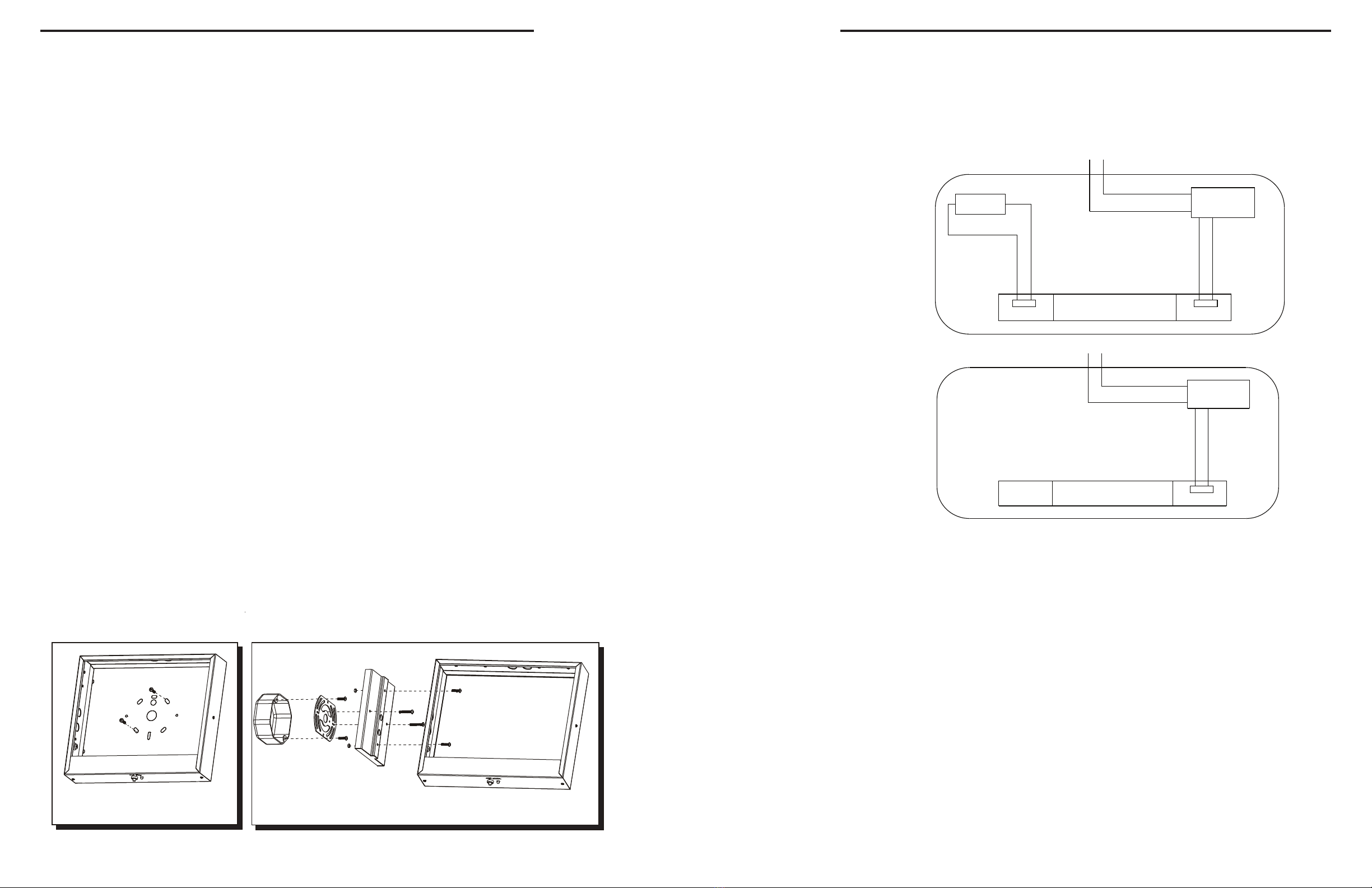
Wiring Diagram
B AT.
L E D B O AR D
P O W E R
B O AR D
W H I T E C O M
O R A N G E 1 0 0 - 3 0 0 V AC
P O W E R
B O A R D
W H I T E C O M
O R A N G E 1 0 0 - 3 0 0 V AC
L E D B O A R D
BATTERY BACKUP
IMPORTANT:
When relamping, only use LED lightsource specified in the sign. Using other LED light source may result in transformer
damage or unsafe conditions. For battery backup models, battery in the unit may not be fully charged. After electricity is
connected to unit, let the battery charge up for at least 24-hrs. The normal operation of the unit should take effect.
AC ONLY
NOTE:
Properly insulate the unused lead with a wire nut or other approved means.
WARNING:
Unused wires must be capped using enclosed wire nuts.
INSTALLATION INSTRUCTIONS
GENERAL
1. This Exit may be shipped with an EXTRA FACE PLATE & RED LENS to make the sign double
face. Replace the BACK PLATE with the extra face plate & lens at the start of the
installation process if the application calls for a double face sign.
PAGE 3
(Figure 1) (Figure 2)
BACK MOUNT INSTALLATION (Figure 1)
Step 1. Extend unswitched 24 hourAC supply of rated voltage to junction box (NOT INCLUDED). Leave at least 18 inches
of slack.
Step 2. Remove retainer screw from side of sign. Remove side panel and lens.
Step 3. Remove 7/8” DIA KO and required mounting pattern from back plate. Use bushing provided to protect wires from
metal edge. Secure wires using cable tie. Feed wires through 7/8” DIA KO bushing.
Step 4. Connect ground in accordance with local codes. Connect wires per schematic and color code as follows: Line 100 -
3OOV- ORANGE; NEUTRAL -WHITE. Cap unused line lead.
Step 5. Mount sign securely to junction box using mounting plate and screws provided.
Step 6. For battery backup models, connect battery leads.Turn on AC supply and operate test switch. LED lamps will stay on
in AC mode and remain on in Emergency mode. For AC only models, turn ON AC supply.
Step 7. Carefully slide glass into sign frame channel and replace end panel and retainer screw.
CEILING or END MOUNT (Figure 2)
Step 1. Follow steps1 to 2 of back-mount instructions.
Step 2. Knock out the appropriate mounting pattern on top or side of unit to accommodate canopy. Use plastic bushings
provided to protect wires from metal edge.
Step 3. FASTEN CANOPY TO SIGN BY MEANS OF (2) SCREWS, STAR WASHERS AND NUTS.
Step 4. Secure mounting plate to junction box by choosing proper slots and using screws supplied with junction box. (NOT
INCLUDED)
Step 5. Feed wires through canopy and connect to supply following step 4 of back-mount instructions.
Step 6. Mount sign with canopy to Juntion box using screws provided.
Step 7. Follow steps 6 to 7 of back-mount instructions.
PAGE 2
SAVE THESE INSTRUCTIONS
Wiring Diagram
B AT.
L E D B O AR D
P O W E R
B O AR D
W H I T E C O M
O R A N G E 1 0 0 - 3 0 0 V AC
P O W E R
B O A R D
W H I T E C O M
O R A N G E 1 0 0 - 3 0 0 V AC
L E D B O A R D
BATTERY BACKUP
IMPORTANT:
When relamping, only use LED lightsource specified in the sign. Using other LED light source may result in transformer
damage or unsafe conditions. For battery backup models, battery in the unit may not be fully charged. After electricity is
connected to unit, let the battery charge up for at least 24-hrs. The normal operation of the unit should take effect.
AC ONLY
NOTE:
Properly insulate the unused lead with a wire nut or other approved means.
WARNING:
Unused wires must be capped using enclosed wire nuts.
INSTALLATION INSTRUCTIONS
GENERAL
1. This Exit may be shipped with an EXTRA FACE PLATE & RED LENS to make the sign double
face. Replace the BACK PLATE with the extra face plate & lens at the start of the
installation process if the application calls for a double face sign.


