manuals.online logo
Brands
  1. Home
  2. •
  3. Brands
  4. •
  5. Cree
  6. •
  7. Lighting Equipment
  8. •
  9. Cree CR150-650L User manual

Cree CR150-650L User manual

1 of 2 LPN000100_D
INSTALLATION INSTRUCTIONS
CR150
INCLUDING CR150-650L, CR150-1000L, CR150-2000L
STEP 1:
Remove CR150 fixture from the packaging. Remove and save the
two screws from the power supply lid. Remove the lid from the
power supply exposing the terminal block. See Figure 1.
STEP 2:
Ensure power is turned off at main power source. If replacing
existing fixture, remove existing fixture from the ceiling opening and
disconnect wires. For new installation, cut a 150-175mm diameter
opening into ceiling for CR150.
STEP 3:
When Installing With Conduit: Remove and discard sheathed
wire installation plate. Select conduit installation plate and remove
knockout holes with screw driver. See Figure 2.
Locate power wires inside the ceiling opening. Pull wires through
conduit. Install and fasten conduit with conduit nut onto supplied
conduit installation plate. Continue to STEP 4.
When Installing With Sheathed Wire: Select sheathed wire
installation plate and discard conduit installation plate. See Figure 2.
TO INSTALL:
1
CR150
8
IP44
IP20
6
7
1
75mm
47,5mm
CAUTION - Tc location
shown is 55°C max
9
63°C
Conduit Installation Plate
Sheathed Wire Installation Plate
IMPORTANT SAFEGUARDS
WARNING - Risk of Electric Shock. Disconnect power at fuse or circuit breaker
before installing or servicing.
READ AND FOLLOW ALL SAFETY INSTRUCTIONS
1. Each luminaire shall be installed only in its intended manner and orientation
2. Luminaire designed for use only on 220-240V, 50/60 Hz, protected circuits from
Circuit Breaker / Fuse Panel.
3. Recommended xed wiring size is 0.75-2.5 sq. mm. Recommended strip length
is 7mm.
4. Installation should only be performed by qualied personnel.
5. The luminaire is to be installed in accordance with the national installation
regulations and electrical codes.
6. Lens portion of luminaire is suitable for IP44 locations. Remainder portion of
luminaire is only suitable for IP20 locations.
7. Suitable for locations with maximum ambient of 35°C.
8. Suitable for damp locations..
SAVE THESE INSTRUCTIONS FOR FUTURE REFERENCE
CEILING OPENING, CEILING THICKNESS COMPATIBILITY
• CR150 fixture is designed to be compatible with 150-175mm diameter ceiling openings.
• Either fixture should be installed in non-insulated ceilings ranging from 1-25mm thick and with maximum above ceiling temperature of
35°C.
• Not all existing ceiling openings that meet these requirements will be compatible with the CR150. To ensure compatibility, a test
installation should be conducted.
FOR AUSTRIALIA (AU) AND NEW ZEALAND (NZ) ONLY, THE
FOLLOWING INSTALLATION IS REQUIRED:
1. Minimum clearance for insulation installation around the product per the “CA80”
requirements in accordance with the NZ requirements as shown below:
2
2. Building insulation abutting the luminaire must meet the following requirements :
a. Insulation abutting the luminaire needs to be of a type that can retain its structural integrity when exposed to maximum surface
temperatures of this luminaire (90C) for CA80
b. Abutting insulation must be able to withstand 30 second needle ame test as per ASNZS 60695.11.5
c. Loose ll insulation as per NZS 4246 is not permitted to abut or cover this down light “batt” style insulation is ok subject to complying to “b”
FOR ALL OTHER COUNTRIES, THE FOLLOWING INSTALLATION IS REQUIRED:
1. Luminaire not suitable for covering with thermally insulated material.
2. Ensure adequate free air space (>50mm) around the entire luminaire and its power supply unit.
2 of 2 LPN000100_D
5 6
REMOVAL OF CR150
NOTE: Ensure power to fixture is
disconnected before attempting to
remove CR150 from ceiling.
To remove fixture from the ceiling,
firmly grasp the outer ring and slowly
pull the fixture from the ceiling.
STEP 4:
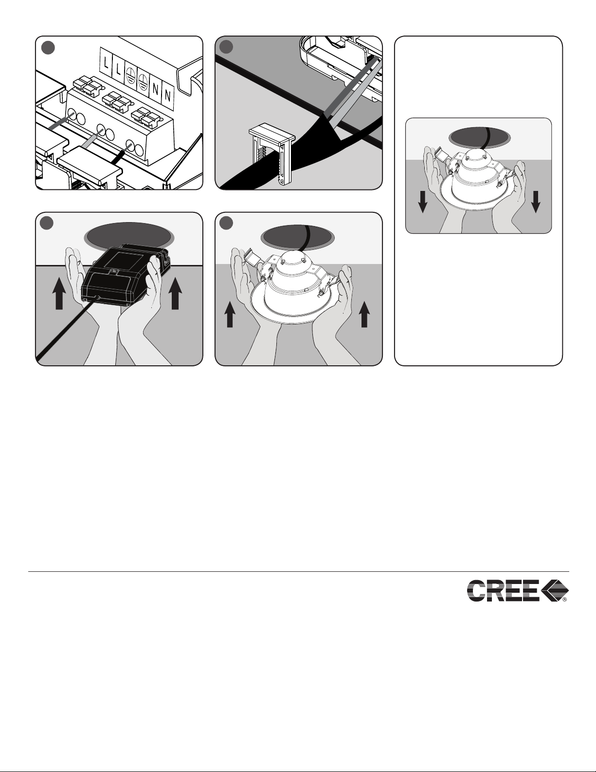
Power Connection: Insert the “Ground”
wire into the terminal block port labeled
with the universal ground symbol. Insert
the “Line” wire into the terminal block
port labeled “L”. Insert the “Neutral” wire
into the terminal block port labeled “N”.
Wire can be inserted into either port
under respective symbol. Ensure wire is
secure in terminal block. Care should be
taken not to damage wiring during this
process. See Figure 3.
NOTE: Maximum current for looping-in is
16A when connecting multiple fixtures.
STEP 5:
Strain relief wires with strain relief clips.
See Figure 4.
STEP 6:
Close lid and re-engage snap features.
STEP 7:
Assemble installation plate onto power
supply lower housing.
STEP 8:
Re-install lid onto power supply by
fastening with screws removed in Step 1
STEP 9:
Insert power supply into ceiling opening.
See Figure 5.
STEP 10:
To insert the CR150 in the ceiling
opening, feed all excess wiring into
ceiling. Carefully rotate both retention
springs up until they reach the lid of the
integrated junction box. Insert the CR150
into the ceiling with wiring or conduit
first. Once the springs are through the
ceiling opening carefully release the
springs allowing the CR150 to seat itself
in the ceiling opening. See Figure 6.
STEP 11:
Installation is complete. Reconnect
power at main power source.
4
3
Limited Warranty: Cree warrants to the original purchaser (the “Buyer”) of the Cree® CR Series downlight purchased (the “Product”), that the Product will be free from material defects in workmanship and materials under normal use and service and conform
to Cree’s written specications. This limited warranty extends for a period of ve (5) years from the date of original purchase of the Product (the “Warranty Period”). There is NO WARRANTY in cases of damage to the Product in transit or damage caused by
your negligence; abuse; abnormal usage; misuse; accidents; damage due to environmental, corrosive or natural elements; improper power supply; failure to follow Cree’s instructions or applicable electrical codes; improper installation, storage or maintenance;
damage due to acts of God; re; vandalism; civil disturbances; power surges; alteration; mishandling; and incorrectly or improperly performing maintenance or repair by someone other than Cree or its authorized service provider. Remedy: If the Product proves
defective during the Warranty Period and the Product return procedures set forth below are followed, Cree will in its sole discretion, as its sole and exclusive obligation under this warranty, refund you the purchase price of the Product, repair the Product or replace
the Product without charge, F.O.B. Cree’s designated facility. Proof of original purchase date (e.g., sales receipt or original invoice) is required for this limited warranty to apply. CREE SHALL NOT BE LIABLE TO BUYER, OR TO ANYONE CLAIMING UNDER
BUYER, FOR ANY OTHER OBLIGATIONS OR LIABILITIES, INCLUDING, BUT NOT LIMITED TO, OBLIGATIONS OR LIABILITIES ARISING OUT OF BREACH OF CONTRACT OR WARRANTY, NEGLIGENCE OR OTHER TORT OR ANY THEORY OF
STRICT LIABILITY, WITH RESPECT TO THE PRODUCTS OR CREE’S ACTS OR OMISSIONS OR OTHERWISE. This limited warranty does not cover the cost of eld labor or expenses related to the repair or replacement of the Product. Cree reserves the
right to utilize new, reconditioned, refurbished, repaired or remanufactured products or parts in the warranty repair or replacement process. Such products and parts will be comparable in function and performance to an original product or part, as determined
by Cree in its sole discretion, and warranted for the remainder of the original warranty period. This limited warranty applies only to a Product purchased within the United States (including the lower 48 states, the District of Columbia, Hawaii, Alaska, Puerto Rico
and the U.S. Virgin Islands, but excluding APO/FPO addresses that are outside of those named jurisdictions) (collectively, the “Territory”). Replacement and repaired Product or parts will only be shipped to addresses within the Territory, and refunds will only be
credited to accounts located within the Territory. Making a Warranty Claim: Notice of any warranty claim should be sent to Cree at the following address: 9201 Washington Avenue, Racine, WI 53406 or you may call Cree at (800) 236-6800 to receive a RGA#
and instructions for return of the Product, freight prepaid. Further Limitations: TO THE EXTENT PERMITTED BY LAW, THE LIMITED WARRANTY AND REMEDIES SET FORTH ABOVE ARE EXCLUSIVE AND IN LIEU OF ALL OTHER WARRANTIES AND
REMEDIES (INCLUDING WITHOUT LIMITATION, ANY IMPLIED WARRANTIES OF MERCHANTABILITY OR FITNESS FOR A PARTICULAR PURPOSE). IF WE CANNOT LAWFULLY DISCLAIM STATUTORY OR IMPLIED WARRANTIES, THEN TO THE
EXTENT PERMITTED BY LAW, ALL SUCH WARRANTIES WILL BE LIMITED IN DURATION TO THE DURATION OF THIS EXPRESS LIMITED WARRANTY AND TO REFUND, REPAIR OR REPLACEMENT SERVICE AS DETERMINED BY CREE IN ITS
SOLE DISCRETION. Some states do not allow limitations on how long an implied warranty lasts, so the above limitation may not apply to you. IN NO EVENT SHALL CREE BE LIABLE FOR INCIDENTAL, COMPENSATORY, CONSEQUENTIAL, INDIRECT,
SPECIAL OR OTHER DAMAGES. CREE’S AGGREGATE LIABILITY WITH RESPECT TO A DEFECTIVE PRODUCT SHALL BE LIMITED TO THE MONIES PAID TO CREE FOR THAT DEFECTIVE PRODUCT. Some states do not allow the exclusion or limita-
tion of incidental or consequential damages, so the above limitation or exclusion may not apply to you. This limited warranty gives Buyer specic legal rights, and Buyer may also have other rights which vary from state to state. Effective Date: January 1, 2013
www.cree.com/lighting

This manual suits for next models

3

Other Cree Lighting Equipment manuals

Cree Link With SmartCast Technology User manual

Cree

Cree Link With SmartCast Technology User manual

Cree OSQ Series User manual

Cree

Cree OSQ Series User manual

Cree C-LITE C-WP-A-FCT3 Series User manual

Cree

Cree C-LITE C-WP-A-FCT3 Series User manual

Cree CR24 UPKIT User manual

Cree

Cree CR24 UPKIT User manual

Cree CR Series User manual

Cree

Cree CR Series User manual

Cree C-AR Series User manual

Cree

Cree C-AR Series User manual

Cree EB14SMK User manual

Cree

Cree EB14SMK User manual

Cree FLEX Series User manual

Cree

Cree FLEX Series User manual

Cree Essentia S-DL4-EB User manual

Cree

Cree Essentia S-DL4-EB User manual

Cree OSQ Series User manual

Cree

Cree OSQ Series User manual

Cree ZR Series User manual

Cree

Cree ZR Series User manual

Cree XLamp ML Family LEDs User manual

Cree

Cree XLamp ML Family LEDs User manual

Cree XLamp XR Series User manual

Cree

Cree XLamp XR Series User manual

Cree OSQ HO Series User manual

Cree

Cree OSQ HO Series User manual

Cree CPY Series User manual

Cree

Cree CPY Series User manual

Cree CXB Series User manual

Cree

Cree CXB Series User manual

Cree OSQ Series User manual

Cree

Cree OSQ Series User manual

Cree LS8 User manual

Cree

Cree LS8 User manual

Cree XLamp MH Series User manual

Cree

Cree XLamp MH Series User manual

Cree LXB Series User manual

Cree

Cree LXB Series User manual

Cree TDS Series User manual

Cree

Cree TDS Series User manual

Cree ESSENTIA S-CT-FB-25L User manual

Cree

Cree ESSENTIA S-CT-FB-25L User manual

Cree ESSENTIA ESA-ADR-414 User manual

Cree

Cree ESSENTIA ESA-ADR-414 User manual

Cree SmartCast FLEX Series User manual

Cree

Cree SmartCast FLEX Series User manual

Popular Lighting Equipment manuals by other brands

MaxLite CID1 operating instructions

MaxLite

MaxLite CID1 operating instructions

American DJ REVO RAVE User instructions

American DJ

American DJ REVO RAVE User instructions

Lumatek Pro DE Reflector Assembly Instructions & Parts List

Lumatek

Lumatek Pro DE Reflector Assembly Instructions & Parts List

Lighting Technologies COLIBRI DL LED Series manual

Lighting Technologies

Lighting Technologies COLIBRI DL LED Series manual

CentoLight Plot 200FZ user manual

CentoLight

CentoLight Plot 200FZ user manual

Lumatek ZEUS 600W PRO 2.9 manual

Lumatek

Lumatek ZEUS 600W PRO 2.9 manual

Costway EP24534 user manual

Costway

Costway EP24534 user manual

Reely 20 59 88 operating instructions

Reely

Reely 20 59 88 operating instructions

Barco SolaSpot LED user manual

Barco

Barco SolaSpot LED user manual

ProLights HZ900D user manual

ProLights

ProLights HZ900D user manual

Robus VEGAS 19.2W quick start guide

Robus

Robus VEGAS 19.2W quick start guide

Ehrgeiz Fusion FS-80 RGBW/1 operating manual

Ehrgeiz

Ehrgeiz Fusion FS-80 RGBW/1 operating manual

Beamz LED PAR 4X 8W Quad Linkable Manual guide

Beamz

Beamz LED PAR 4X 8W Quad Linkable Manual guide

strex SP148 instruction manual

strex

strex SP148 instruction manual

LED Linear VARIOLED FLEX HYDRA LD40 installation instructions

LED Linear

LED Linear VARIOLED FLEX HYDRA LD40 installation instructions

Rocky's Eazy Roller 4A Permanent instructions

Rocky's

Rocky's Eazy Roller 4A Permanent instructions

Quoizel HTH8411MB installation guide

Quoizel

Quoizel HTH8411MB installation guide

ARRI EB 400/575 D operating instructions

ARRI

ARRI EB 400/575 D operating instructions

manuals.online logo
manuals.online logoBrands
  • About & Mission
  • Contact us
  • Privacy Policy
  • Terms and Conditions

Copyright 2025 Manuals.Online. All Rights Reserved.