manuals.online logo
Brands
  1. Home
  2. •
  3. Brands
  4. •
  5. Hubbell
  6. •
  7. Accessories
  8. •
  9. Hubbell KILLARK VSI30 Series Instruction Manual

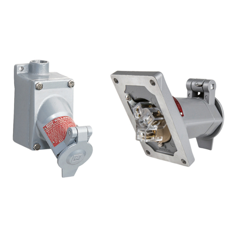
Hubbell KILLARK VSI30 Series Instruction Manual

P/N KIL00912478 FORM NO. K1287 1007 ERO-7-005-06 Side 1 of 2
HUBBELL ELECTRICAL PRODUCTS
A Division of HUBBELL INCORPORATED (Delaware)
3940 Martin Luther King Drive
St. Louis, Missouri 63113 USA
www.Hubbell-Killark.com
INSTALLATION, OPERATION & MAINTENANCE DATA SHEET
FOR
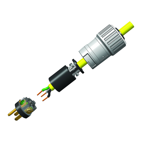
VSI30 Series Receptacles and Plugs
30 Amp Receptacle VSI30R and Plug VSI30P
For Hazardous and Corrosive Applications
Please read this entire document
before beginning any work.
1. Safety Instructions 3.2 Conduit/Cable Installation
Installation and maintenance of these plugs and receptacles
should only be performed by skilled and experienced
personnel in accordance with the National Electrical Code
(NEC) (NFPA 70) and any local regulations which relate to
hazardous (classified) locations.
For conduit installation, connect rigid conduit to the hub and
avoid misalignment.
For cable installation, connect a listed cable fitting.
Conduit or cable fittings should not be tightened more than 50
ft-lbs (68 N-m) of torque.
CAUTION:
∗Disconnect power supply before installing or servicing
these plugs and/or receptacles.
∗A modification to this product, other than noted on this form,
is not permitted.
∗Operate only undamaged and clean plugs & receptacles with
observations of the operating parameters in section 2.
∗For a Class I Zone 1 conduit installation, conduit seals are
required; refer to NEC 505.16 (B) (1). For any other cable or
conduit installation NO seals are required.
∗Use only approved wiring methods for the location, with the
associated conduit/cable fittings.
∗The receptacle is suitable for use on a circuit capable of
delivering not more than 10,000 rms symmetrical amperes,
600V maximum, when protected by properly sized Class J
fuses.
2. Technical Data
Please refer to the technical data on the nameplates.
3.3 Wiring
Open the terminal cover and connect the supply conductors. If
Tais < 45°C, use 75°C rated wire; if Tais > 45°C use
90°C wire. The terminals accept up to two wires which are 14
AWG through 8 AWG per terminal. Allow proper length for
bending and cut the conductors to length. Strip the conductor
insulation 13/32" (10 mm) from the end. Insert the conductors
into the appropriate terminals which are marked to correspond
with the markings inside the plug. Torque all terminal screws to
16 in-lbs (1.8 N-m); including all unused terminals.
3.4 Installation of Auxiliary Contact Block (optional)
One or two blocks, either for I.S. or
non-I.S. circuits can be installed by
snapping them into either side of the
main terminal block. These contact
blocks also can be retrofitted and
must be installed according to IOM
Form No. K1289. See Parts and Accessories for block types.
2.1 Certification:
FM Project: 3024590 & CSA File 240743
Class I, Zone 1 & 2, AEx de IIC T*
Ex de IIC T*
Class I, Division 2, Groups ABCD;
Class II, Division 1&2, Groups EFG; Class III
*Temp. Class T6 at Ta<40°C, T5 at Ta<55°C.
3.5 Installation of Additional Entries
Additional top and side wiring entries can be installed in the
receptacle by punching through hole(s) 1-3/8" nominal dia. for
1" NPT. Use the mounting kit P/N YOST8571801290. The kit
contains one brass bonding plate, two locknuts with two 1"
NPT threaded holes and one bonding jumper with connection
2.2 Ambient temperature range:
-22°F to +131°F (-30°C to +55°C). screw. Insert entry fitting through the enclosure hole, tighten
into the bonding plate and secure with locknut. Connect the
2.3 Storage temperature range:
-67°F to +212°F (-55°C to +100°C). bonding jumper to the terminal marked . A second 1" NPT
bottom fitting can be installed by removing the close-up plug
2.4 Environmental protection: IP 66 / Type 3, 4, 4X.
Covers must be tight when plug is not inserted to maintain
environmental protection. Observe the labels on the plug and
and installing a 1" NPT fitting with locknut in it’s’ place. See
Parts and Accessories.
4. Horsepower Rating
receptacle.
3. Receptacle Installation
3.1 Enclosure mounting
Securely mount the receptacle in a vertical position using four
1/4" (6 mm) screws and suitable washers. Dimensions are
marked on the back of the receptacle housing.
Voltage AC 3-Phase
600V 25 HP SEE PLUG WIRING
480V 20 HP INSTRUCTIONS ON
240V 10 HP REVERSE SIDE
120V 5 HP

P/N KIL00912478 FORM NO. K1287 1007 ERO-7-005-06 Side 2 of 2
INSTALLATION, OPERATION & MAINTENANCE DATA SHEET
Figure 1
5. Wiring of Plug VSI30P
5.1 Cord Type
Select a flexible cord with copper conductors of the
appropriate insulation, ampacity, and temperature (75°C or
90°C) rating. For installations in the U.S., refer to the
5.6 Connection to Terminals
Flip the strain relief (7) out of the way. Attach the leads to the
appropriate terminals and torque with 16 in-lbs (1.8 N-m).
CAUTION: The Equipment Grounding Conductor (green wire)
is to be connected to the terminal marked .
NEC, section 400.4, 400.5, 501.140, 502.140 and 503.140.
NOTE: Cords with O.D. between 0.6" and 1.1" can be
used. Maximum wire range for plug terminals is 1 x
14 AWG up to 1 x 8 AWG.
5.2 Cord Preparation
5.7 Strain Relief
Open the clamp (7) and adjust the clamping size to the O.D. of
the cord (this may require removing 1 or 2 of the clamp inserts,
if necessary). Then flip the strain relief back and clamp the
cord using 14 in-lbs (1.6 N-m) torque.
Cut the cord cleanly - Do not strip away cord jacket or
conductor insulation at this time.
5.3 Opening the Plug
Referring to Figure 1 above, loosen screws (1) and remove
the plug housing (2). Then unscrew the compression collar
(3) and remove the close-up disc (4) and discard it. Then
remove the friction washer (5) and grommet (6).
5.8 Plug Assembly
Rejoin the two parts of the plug enclosure paying careful
attention to the orientation of the alignment tap and reinstall
the three screws (1). Slide the grommet (6) into position in the
receiving cavity of the plug housing, then place the friction
washer against the grommet and turn on the compression
collar until a good compression is achieved.
5.4 Insert the Cord
Guide the compression collar (3) and the friction washer (5),
over the cord.
5.4.1 Install Cord Grommet
6. Maintenance
The only maintenance is a periodic inspection for damage and
proper operation. The surface of the plug pins and the pin
chamber should be kept clean. Keep cap (9) on plug when not
The grommet (6) is a universal onion ring style which
accommodates several cord diameters by removing (cutting
out) the inner undersized diameters. The grommet should fit
snugly on the cord. The grommet may require lubrication in
order to slide over the cord. Use talcum powder or an
equivalent material rated for use on electrical products. Slide
the grommet over the cord with the cuts toward the plug
housing (2).
NOTE: If the grommet slides freely over the cord, there will be
insufficient sealing for Class II and Class III Hazardous
Locations.
5.4.2 Install Strap and Plug Housing on Cord
Slide the strap ring (8) and the plug housing (2) over the
cord.
in use. Any damaged equipment should be replaced promptly
to ensure the electrical safety and explosion protection of the
system.
7. Parts and Accessories Part Number
Plug Cap for 3-pole, 4-wire YOST8571001140
Plug Cap for 4-pole, 5-wire YOST8571002140
Auxiliary Contact Block NC VSIAUXNC
Auxiliary Contact Block NO VSIAUXNO
Aux. Contact Block NC for I.S. Circuit VSIAUXNCIS
Aux. Contact Block NO for I.S. Circuit VSIAUXNOIS
Polymeric Close-up Plug 1" NPT PD-E-4-0-31-00
Conduit Hub 1" NPT 8166/11-03-N
Locknut 1" NPT KILLN3
Hub Mtg. Kit 1" for 4 & 5-wire recept. YOST8571801290
5.5 Cord Preparation
Dress the cord by removing the outer jacket and fillers for a
length of 2 ½" (63 mm) and strip 2 ½”
the insulation off of each ½”
conductor a distance of ½"
(12 mm) from the end.
Note: The nature of these instructions is only informative and does not
cover all of the details, variations or combinations in which this
equipment may be used, stored, transported, installed, operated or
maintained. Since conditions of use of the product are outside of the
care, custody and control of the manufacturer, the purchaser should
determine the suitability of the product for his intended use, and
assumes all risk and liability whatsoever in connection therewith.

This manual suits for next models

2

Other Hubbell Accessories manuals

Hubbell LightOWL LODT Manual

Hubbell

Hubbell LightOWL LODT Manual

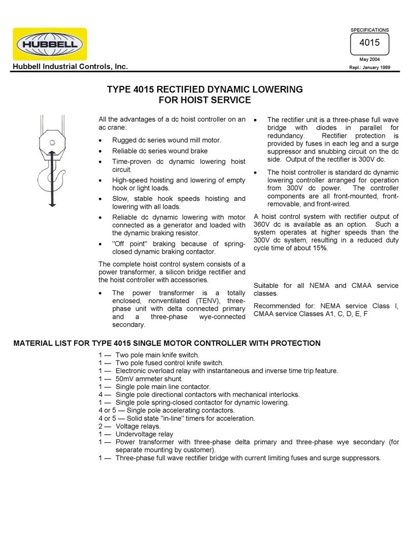
Hubbell Single Motor Controller 4015 User manual

Hubbell

Hubbell Single Motor Controller 4015 User manual

Hubbell Gear Drive Electric Cable Reels S-28 User manual

Hubbell

Hubbell Gear Drive Electric Cable Reels S-28 User manual

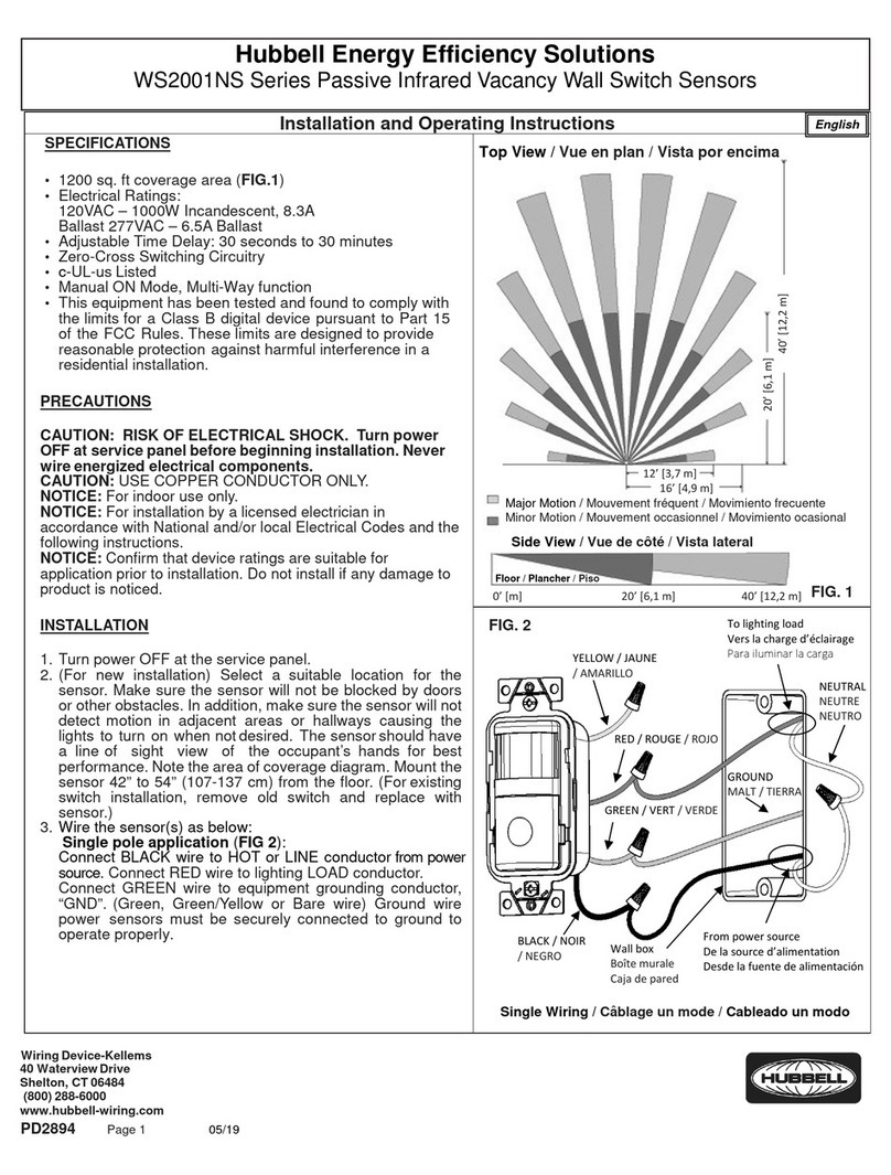
Hubbell WS2001NS Series User manual

Hubbell

Hubbell WS2001NS Series User manual

Hubbell Gear Drive Electric Cable Reels SM-24 User manual

Hubbell

Hubbell Gear Drive Electric Cable Reels SM-24 User manual

Hubbell NX Distributed Intelligence NXSMP-LMO User manual

Hubbell

Hubbell NX Distributed Intelligence NXSMP-LMO User manual

Hubbell LightOWL LODT Manual

Hubbell

Hubbell LightOWL LODT Manual

Hubbell H-MOSS WS Series User manual

Hubbell

Hubbell H-MOSS WS Series User manual

Hubbell Direct Drive Electric Cable Reels S-16 User manual

Hubbell

Hubbell Direct Drive Electric Cable Reels S-16 User manual

Hubbell Gear Drive Electric Cable Reels SM21 User manual

Hubbell

Hubbell Gear Drive Electric Cable Reels SM21 User manual

Hubbell Electric Cable Reels TMR Series User manual

Hubbell

Hubbell Electric Cable Reels TMR Series User manual

Hubbell LightHawk LHMT User manual

Hubbell

Hubbell LightHawk LHMT User manual

Hubbell Dual Hose Reel R-35 User manual

Hubbell

Hubbell Dual Hose Reel R-35 User manual

Hubbell KILLARK ACCEPTOR UGP Series Instruction Manual

Hubbell

Hubbell KILLARK ACCEPTOR UGP Series Instruction Manual

Hubbell WS Series User manual

Hubbell

Hubbell WS Series User manual

Hubbell KILLARK ACCEPTOR UGR Series Instruction Manual

Hubbell

Hubbell KILLARK ACCEPTOR UGR Series Instruction Manual

Hubbell Electric Cable Reels SHO Series User manual

Hubbell

Hubbell Electric Cable Reels SHO Series User manual

Hubbell Direct Drive Electric Cable Reels S-21 User manual

Hubbell

Hubbell Direct Drive Electric Cable Reels S-21 User manual

Hubbell NX Distributed Intelligence NXSMP-OMNI User manual

Hubbell

Hubbell NX Distributed Intelligence NXSMP-OMNI User manual

Hubbell NX Distributed Intelligence NXSMP-LMI User manual

Hubbell

Hubbell NX Distributed Intelligence NXSMP-LMI User manual

Hubbell Gear Drive Electric Cable Reels SM32 User manual

Hubbell

Hubbell Gear Drive Electric Cable Reels SM32 User manual

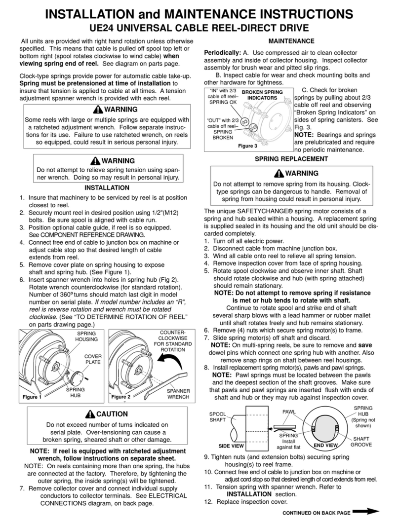
Hubbell Universal Cable Reel-Direct Drive UE24 User manual

Hubbell

Hubbell Universal Cable Reel-Direct Drive UE24 User manual

Hubbell Direct Drive Electric Cable Reels MMD32 User manual

Hubbell

Hubbell Direct Drive Electric Cable Reels MMD32 User manual

Hubbell AFBS1R4 Series User manual

Hubbell

Hubbell AFBS1R4 Series User manual

Popular Accessories manuals by other brands

Rinstrum R323 Communications manual

Rinstrum

Rinstrum R323 Communications manual

Franklin Electric SubDrive Duplex Alternator installation manual

Franklin Electric

Franklin Electric SubDrive Duplex Alternator installation manual

ratiotec TowerBank instruction manual

ratiotec

ratiotec TowerBank instruction manual

Siemens SIWAREX JB operating instructions

Siemens

Siemens SIWAREX JB operating instructions

Bosch rexroth PSM instruction manual

Bosch

Bosch rexroth PSM instruction manual

Banner Q4X Series instruction manual

Banner

Banner Q4X Series instruction manual

BIRD 4044 Series Operation manual

BIRD

BIRD 4044 Series Operation manual

Nera WILINK I System manual

Nera

Nera WILINK I System manual

WDT DUFTDOS AK-I Operation manual

WDT

WDT DUFTDOS AK-I Operation manual

HBM FS64 installation guide

HBM

HBM FS64 installation guide

SensComp SonaSwitch MINI-S Installation and operation manual

SensComp

SensComp SonaSwitch MINI-S Installation and operation manual

Keysight N8481S Operating and service guide

Keysight

Keysight N8481S Operating and service guide

Telco Sensors SpaceMaster Series user manual

Telco Sensors

Telco Sensors SpaceMaster Series user manual

Master SHAKE EVO manual

Master

Master SHAKE EVO manual

Summit Dual Pro manual

Summit

Summit Dual Pro manual

Brunton Metal 4400 user manual

Brunton

Brunton Metal 4400 user manual

Motorfist Argo Avalanche user manual

Motorfist

Motorfist Argo Avalanche user manual

poly-planar IP-100 installation instructions

poly-planar

poly-planar IP-100 installation instructions

manuals.online logo
manuals.online logoBrands
  • About & Mission
  • Contact us
  • Privacy Policy
  • Terms and Conditions

Copyright 2025 Manuals.Online. All Rights Reserved.