manuals.online logo
Brands
  1. Home
  2. •
  3. Brands
  4. •
  5. Hubbell
  6. •
  7. Fan
  8. •
  9. Hubbell REKF FAN KIT User manual

Hubbell REKF FAN KIT User manual

This manual suits for next models

1

Other Hubbell Fan manuals

Hubbell Progress Lighting P250017 User manual

Hubbell

Hubbell Progress Lighting P250017 User manual

Hubbell Progress Lighting P250018 User manual

Hubbell

Hubbell Progress Lighting P250018 User manual

Popular Fan manuals by other brands

Minka Group minkaAire Wave F843 instruction manual

Minka Group

Minka Group minkaAire Wave F843 instruction manual

Airflow Adroit DV50 instruction manual

Airflow

Airflow Adroit DV50 instruction manual

Vornado 270 Series owner's guide

Vornado

Vornado 270 Series owner's guide

comfort air TH-10D instruction manual

comfort air

comfort air TH-10D instruction manual

Livoo DOM386 instruction manual

Livoo

Livoo DOM386 instruction manual

Holmes BLIZZARD HAOF-90 owner's guide

Holmes

Holmes BLIZZARD HAOF-90 owner's guide

Taurus GRECO 16 ELEGANCE manual

Taurus

Taurus GRECO 16 ELEGANCE manual

Quorum PINNACLE installation instructions

Quorum

Quorum PINNACLE installation instructions

Monte Carlo Fan Company 3DIR58RBD-V1 Owner's guide and installation manual

Monte Carlo Fan Company

Monte Carlo Fan Company 3DIR58RBD-V1 Owner's guide and installation manual

Craftmade UH52 installation guide

Craftmade

Craftmade UH52 installation guide

Jocel JVA030658 instruction manual

Jocel

Jocel JVA030658 instruction manual

MIKA MFB1211/GR user manual

MIKA

MIKA MFB1211/GR user manual

Harbor Breeze RLG52NWZ5L manual

Harbor Breeze

Harbor Breeze RLG52NWZ5L manual

Allen + Roth L1405 instruction manual

Allen + Roth

Allen + Roth L1405 instruction manual

ViM KUBAIR F400 ECOWATT Technical manual

ViM

ViM KUBAIR F400 ECOWATT Technical manual

HIDRIA R10R-56LPS-ES50B-04C10 user guide

HIDRIA

HIDRIA R10R-56LPS-ES50B-04C10 user guide

BLAUBERG Ventilatoren CENTRO-M 100 L user manual

BLAUBERG Ventilatoren

BLAUBERG Ventilatoren CENTRO-M 100 L user manual

Triangle Engineering HEAT BUSTER SPL Series owner's manual

Triangle Engineering

Triangle Engineering HEAT BUSTER SPL Series owner's manual

manuals.online logo
manuals.online logoBrands
  • About & Mission
  • Contact us
  • Privacy Policy
  • Terms and Conditions

Copyright 2025 Manuals.Online. All Rights Reserved.

Hubbell Premise Wiring, HUBBELL INCORPORATED (Delaware)
14 Lord's Hill Rd, Stonington CT 06378 (800) 626-0005, Fax (860) 535-8328
www.hubbell-premise.com
Control No. Page of
Rev. Date: Hubbell Premise Wiring Instruction Sheet
®Control No. Page of
Rev. Date:
STEP 1:
A) Locate airflow directional arrow imprinted on outside of fan
housing. Arrow indicates direction of airflow. Arrow should
point up, when assembling, to ensure air intake into cabinet
as shown in Fig. 1.
B) Power cord (item11) can be used by either side wiring to
receptacle or by terminating with two prong plug (supplied).
1) For side wiring assemble grommet/strain relief
(item 13) to power cord (item 11) as shown in Fig. 2.
2) For terminating with two prong plug assemble plug
(item 12) to power cord (item 11) as shown in Fig. 3.
Fig. 2 Fig. 3
13
12
11
11
77877301 1 4
F 22JAN04
77873301 4 4
F 22JAN04 FAN ACCESSORY
PARTS LIST: REKF, REKFF
Item Description Qty
1 Fan 1
2 Wire, Fan Guard 2
3 Lock Nut 4
4 Rubber Washer 4
5 Fan Bracket 1
6 Fan Bracket Spacer 1
7 #6-32 x 2" Pan Head Screws 4
8 #6-32 x 2" Flat Head Screws 4
9 Adhesive Air Baffles 1
10 Foam Plenums 2
11 Power Cord 1
12 AC Plug 1
13 Grommet / Strain Relief 1
(For 1/2" Knockout)
14 Filter Bracket 1
15 Filter 2
16 3" Foam 4
Notes:
Please read entire instructions before assembling.
Compare contents with above parts list to ensure that you
have received all parts.
Use door seal/gasket kit (HPW catalog #REKG) to enhance
performance of fan.
Use Rebox power kit (HPW catalog #REKP) to prepare
Rebox for power.
2
44
15
12
DIRECTION
OF AIR FLOW
REKFF
This instruction sheet applies to the following Hubbell Premise Wiring (HPW) catalog numbers: REKF FAN KIT
REKFF FILTER KIT
Direction of Air Flow
Fig. 1
1
2
3
5
10
9
8
7
12
13
4
11
6
5
14
15
16
12
Hubbell Premise Wiring, HUBBELL INCORPORATED (Delaware)
23 Clara Dr Mystic, CT 06355 (800) 626-0005, Fax (860) 535-8328
www.hubbell-premise.com
Control No. Page of
Rev. Date:
Control No. Page of
Rev. Date:
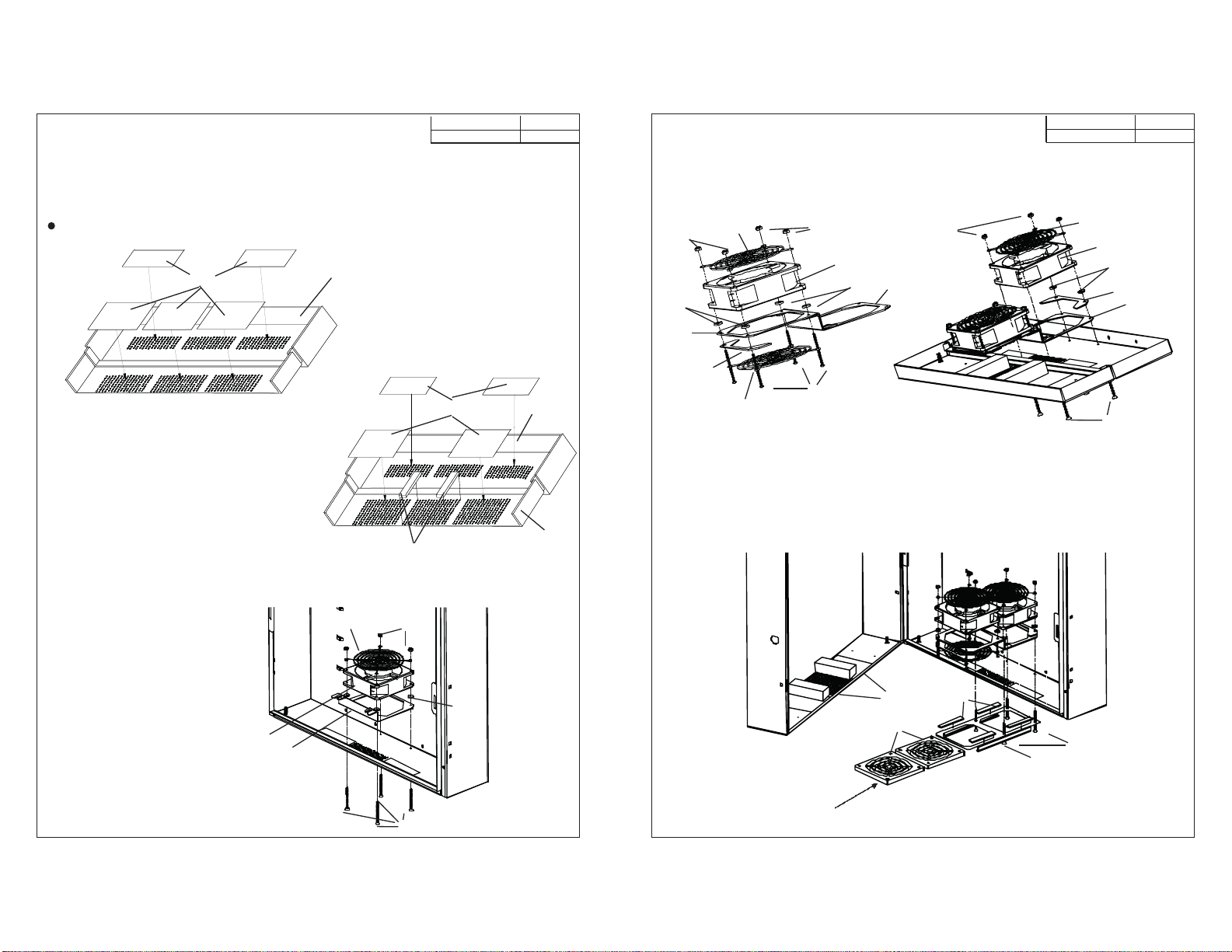
STEP 2: Installing Adhesive Air Baffles and Foam Plenums into Cabinet
A) When using one fan:
1) Remove backing from adhesive air baffles (item 9) and install in cabinet as shown in Fig. 4.
B) When using two fans (RE4 only):
1) Remove backing from adhesive air baffles (item 9) and foam plenums (item 10) and install in cabinet as
shown in Fig. 5.
Adhesive air baffles are used to enhance airflow over active equipment.
77877301 2 4
F 22JAN04
77877301 3 4
F 22JAN04
C) When using two fans with filters: (RE4, RE4X, & IDF CABINETS ONLY)
1) While assembling fan Kit (REKF) to the body of the Cabinet, peel adhesive backing off all four (4) 3"
foam strips (item 16), align and press onto filter bracket (item 14). Use (4) fan mounting flat head
screws. (Item 8) to secure filter bracket (item 14) as shown in Fig.9.
2) Slide filter (Item 15) as shown, one after another.
B) When using two fans (RE4 only):
1) Assemble one fan (item 1), one bracket spacer (item 6), four (4) rubber washers (item 4), two (2) wire fan
guards (item 2), to fan brackets (item 5) as shown in Fig. 7, using four (4) pan head screws (item 7), and
four (4) lock nuts (item 3).
2) Assemble second fan (item 1), and one bracket spacer (item 6) and four (4) rubber washers (item 4) to
fan brackets (item 5). Mount to cabinet as shown in Fig. 8 using the same mounting hardware as
mentioned above.
10 Fig. 5
Cabinet
Fig. 4
Fig. 6
1
2
4
3
7
5
STEP 3: Assembling/Installing Fan into Body of Cabinet
A) When using one fan:
1) Mount fan assembly to inside bottom surface of cabinet in
order as shown:
(item 5) - fan bracket
(item 4) - rubber washer
(item 1) - fan
(item 2) - wire fan guard
2) Secure in place using
four (4) pan head screws (item 7) and
four (4) lock washers (item 3). 16
8
14
15
10
Fig.9
Fig. 7
7
5
2
6
1
5
4
4
3
3
2
9
9Cabinet
Door
Fig. 8
7
4
1
3
5
6
2