Hubbell inSIGHT HBLGW0400EEUS2 User manual

Hubbell Ethernet Gateway V1.1 User’s Manual
PD2864 6/19 Page 1
Contents
Contents .................................................................................................................................................1
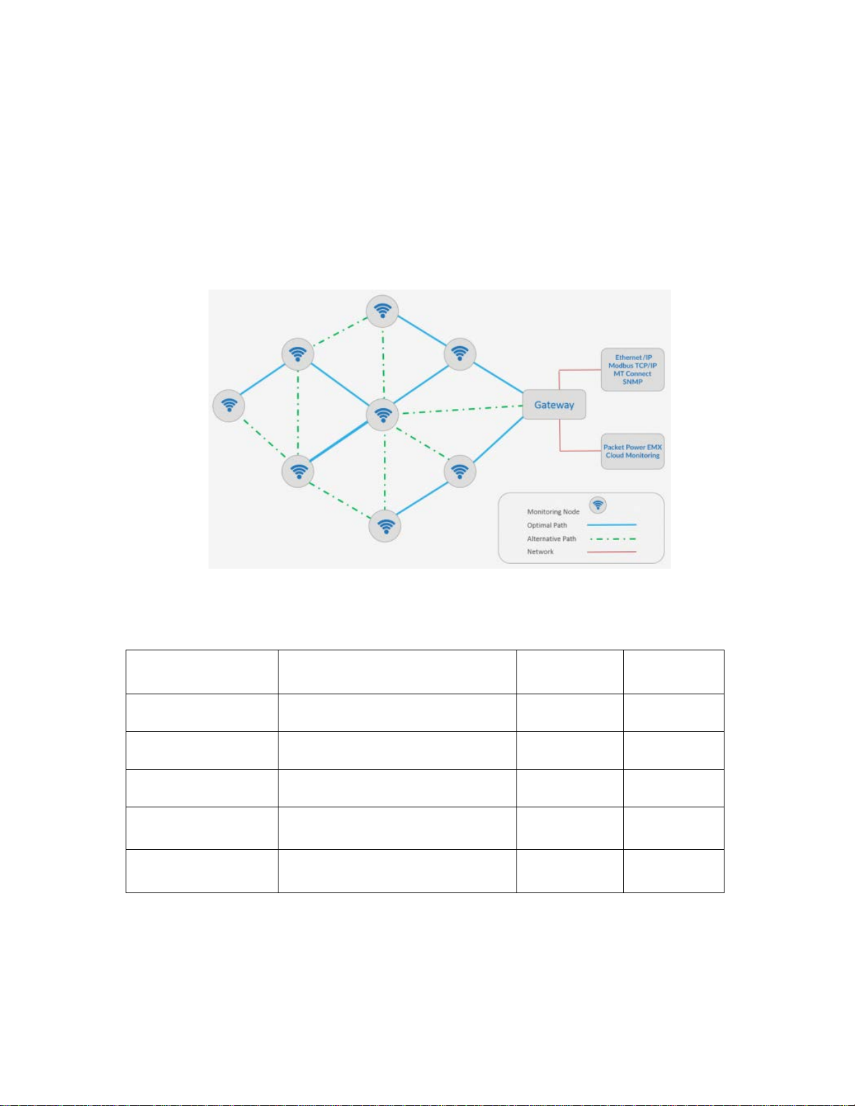
Ethernet Gateway Overview...................................................................................................................3
Network Configuration............................................................................................................................4
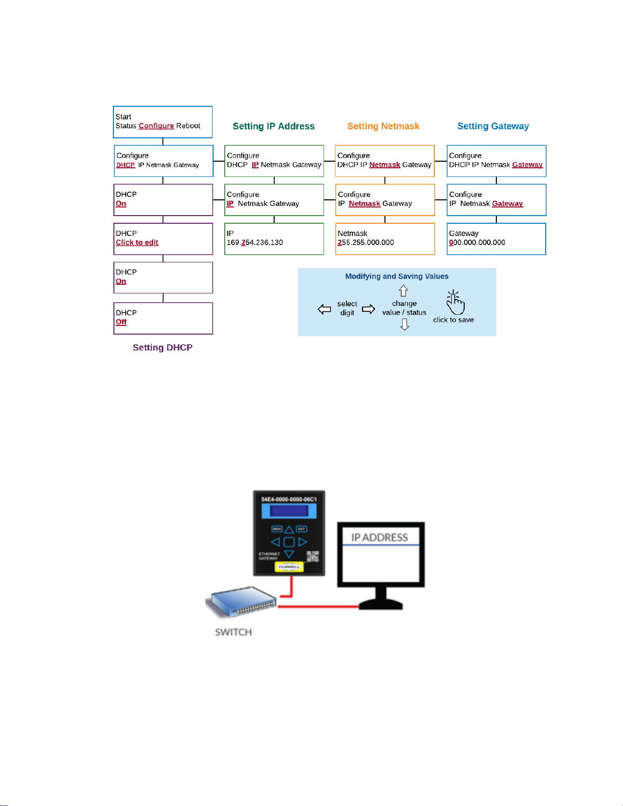
Configuring Network Settings.............................................................................................................4
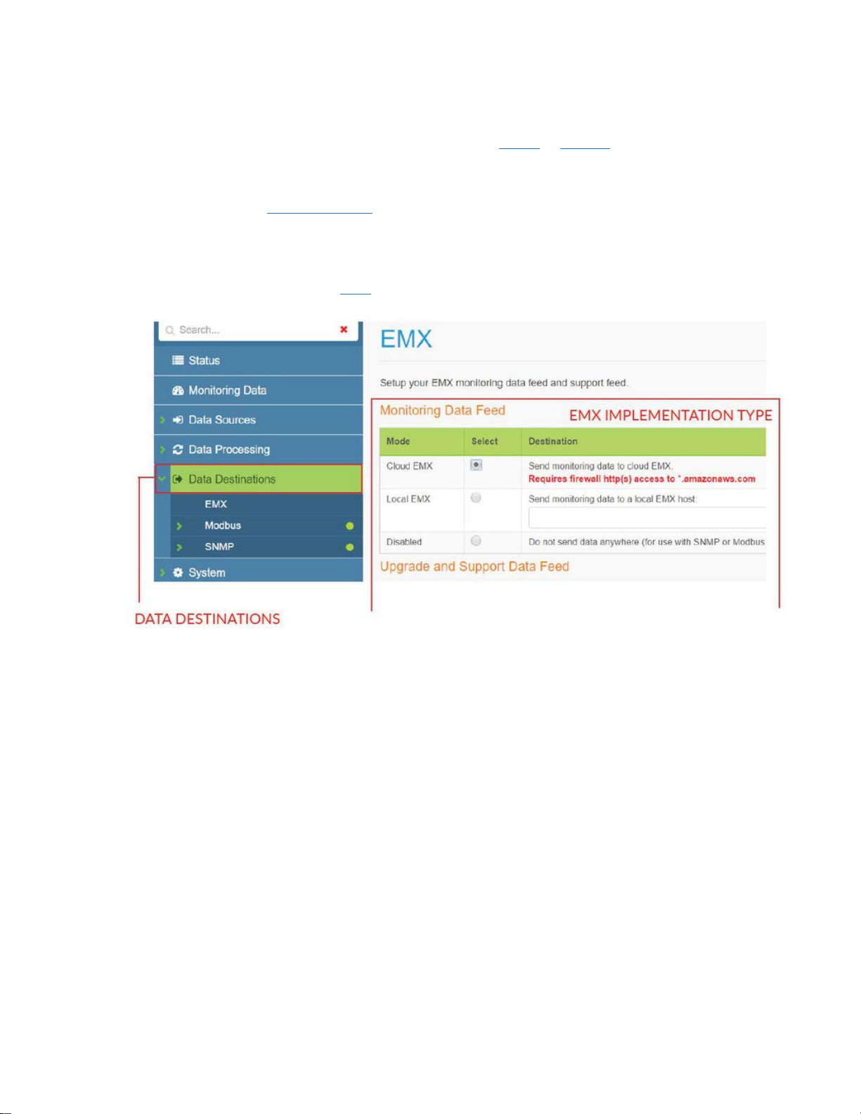
Configuring using the Gateway Web Console...................................................................................6
Physical Installation..............................................................................................................................10
Placement Guidelines ......................................................................................................................10
Mounting Bracket .............................................................................................................................11
Power ...............................................................................................................................................12
Gateway Web Console.........................................................................................................................13
Status ...............................................................................................................................................13
Monitoring Data................................................................................................................................14
Update images to Hubbell gages.......................................................Error! Bookmark not defined.
Data Sources....................................................................................................................................15
Data Destinations.............................................................................................................................17
System .............................................................................................................................................18
Firmware Upgrades..............................................................................................................................27
SNMP Implementation..........................................................................................................................28
Data Output from SNMP Gateways.................................................................................................28
Accessing the Gateway Console .....................................................................................................29
Accessing the MIB files from Gateway Console..............................................................................29
Accessing active OIDs .....................................................................................................................31
Viewing monitoring node readings on the Gateway Console..........................................................32
Uploading an SNMP license to the Gateway...................................................................................33
Enabling and configuring the SNMP Agent......................................................................................34
Using the iReasoning MIB browser..................................................................................................35
Virtual IP addressing / Assigning Virtual IPs to monitoring nodes...................................................40
Modbus TCP/IP Implementation...........................................................................................................45
Modbus Overview.............................................................................................................................45
Peering Gateways and Using a Master Gateway............................................................................45
Enabling Modbus Output..................................................................................................................46
Enabling and Configuring the Modbus Driver..................................................................................47
Viewing and Verifying Monitoring Data using the Gateway Console...............................................48
Register Maps..................................................................................................................................48
Manually Assigning Registers and Register Maps...........................................................................50

Hubbell Ethernet Gateway V1.1 User’s Manual
PD2864 6/19 Page 2
Modbus Device IDs..........................................................................................................................52
Accessing and Verifying Modbus Readings Using the Gateway Console.......................................54
Exporting Modbus Readings............................................................................................................55
MTConnect Implementation .................................................................................................................56
EthernetIP Implementation...................................................................................................................57
Technical Specifications.......................................................................................................................59
Regulatory Information and Labels.......................................................................................................60
Regulatory Information.....................................................................................................................60
Regulatory Label..............................................................................................................................61

Hubbell Ethernet Gateway V1.1 User’s Manual
PD2864 6/19 Page 3
Ethernet Gateway Overview
The Ethernet Gateway is a key component of the Hubbell system architecture. It provides an interface
between the wireless monitoring devices and the monitoring application. The Gateway automatically
detects any new monitoring devices, seamlessly adding them to the network.
All Gateways need to be installed and configured to run on the local Ethernet network. If the
monitoring application is gathering data using SNMP or Modbus protocols, some additional steps are
needed that are specific to each of those protocols.
Gateway Models (US2 models also available)
Model Number Description Protocol Monitoring
units
HBLGW04000EUS1
HBLGW04000LUS1 Ethernet Gateway V4 EMX
100
30
HBLGW0400MEUS1
HBLGW0400MLUS1 Ethernet Gateway V4 Modbus Modbus
TCP/IP
100
30
HBLGW0400SEUS1
HBLGW0400SLUS1 Ethernet Gateway V4 SNMP SNMP
100
30
HBLGW040MTEUS1
HBLGW040MTLUS1 Ethernet Gateway V4 MT Connect MTConnect®100
30
HBLGW0400EEUS1
HBLGW0400ELUS1 Ethernet Gateway V4 Ethernet/IP EtherNet/IP™ 100
30

Hubbell Ethernet Gateway V1.1 User’s Manual
PD2864 6/19 Page 4
Network Configuration
Installing the Ethernet Gateway
Each location in which Smart Power Cables are deployed must have one or more Hubbell Ethernet
Gateways to gather data from the Smart Power Cables.
Refer to Hubbell’s Ethernet Gateway User’s Manual or Quick Start Guide for more information.
Configuring Network Settings
The Gateway requires an IP address prior to being network accessible unless it is being used in
DHCP mode.
Before setting the IP address make sure that you have the following data provided to you by your IT
administrator.
1) IP Address
2) Gateway
3) Netmask (subnet mask)
4) DNS
Using the touchpad to navigate
If the Gateway is new and does not have an IP address, you can enter the IP address directly onto
the Gateway using the on board "touchpad" and display.
After the Gateway is energized and completes its boot sequence (approximately 30-60 seconds), the
Network Status menu will appear.
This will reveal details about the Gateway's version, IP address (if previously programmed), MAC
address, and Uptime (duration since last energization).
To navigate the menu, press the touchpad in a corresponding direction and “tap” to enter a selection.

Hubbell Ethernet Gateway V1.1 User’s Manual
PD2864 6/19 Page 5
Gateway LCD menu
The network status menu will display any configured network parameters.
Version: Gateway's firmware version
IP Address: Programmed IP address
MAC Address: Applicable MAC address
System Reboot: Reboots the Gateway
Uptime: Total time since the Gateway was last energized
Turning DHCP on/off using the local LCD Menu
The Gateway is provided with DHCP "on" as a default.
DHCP addressing relies on the server to automatically assign the IP information eliminating the need
to manually input the IP addressing.
To enable manual IP addressing, as required in most cases, it is necessary to turn DHCP off by
following the menu instructions below.
When DHCP is turned off, the configuration menu will reveal options for inputting IP address
information.
Entering IP address data using the local LCD Menu
With DHCP turned off the Configure menu will reveal options for setting the IP address, Netmask and
Gateway.
All of these parameters need to be filled in before the Gateway can be operational.
If you do not have this information it can be provided to you by your network administrator.

Hubbell Ethernet Gateway V1.1 User’s Manual
PD2864 6/19 Page 6
Configuring using the Gateway Web Console
Once an IP address is assigned to the Gateway either manually or via DHCP, you can access the
Gateway console using a standard web browser and entering the IP address of the Gateway.
This requires that the Gateway be connected via Ethernet network router or switch. Under some
circumstances the Gateway can be accessed and configured directly from a PC but many enterprise
systems prevent external IP addressing functions on a PC.
The Gateway console is described in greater detail online at: https://dox.packetpower.com/ Ethernet-
--Gateway---Version---4---Web---Console.html???
The Gateway Console status screen will appear as shown below.

Hubbell Ethernet Gateway V1.1 User’s Manual
PD2864 6/19 Page 7
To access the network settings, click the "System" tab on the left.
In the System tab sub menu, click the “Networking” tab.
If DHCP is “on” you will not be able to access any network setting until it is switched off under the
Network Interface section.
When DHCP is turned off the network settings will be revealed in the Network Interface section.
It is now possible to modify the IP address, Netmask, Gateway addresses.

Hubbell Ethernet Gateway V1.1 User’s Manual
PD2864 6/19 Page 8
If using DNS (Domain Name Servers), input the server address under the Domain Name Server
section.
In order for the Gateway to have a proper time reference, a NTP server address is needed in
the Time Synchronization Section.
The default time servers are 0.pool.ntp.org and 1.pool.ntp.org. Once a time server is entered confirm
the time at the top right of console. For more information on available NTP servers see the NTP server
section. The time will be expressed in the top right corner of the Console screen.
Configuring Data Destinations
Data Destinations configures how the Gateway delivers data. The Gateway can make monitoring
data accessible via three formats:
1. EMX Monitoring Portal – Note: data can be provided simultaneously to the EMX Portal while
serving Modbus TCP/IP or SNMP data.
2. Modbus TCP/IP
3. SNMP (versions 1,2 and 3)
Configure the data destinations following these steps:
1. Click on the “Data Destinations” tab on the left menu.

Hubbell Ethernet Gateway V1.1 User’s Manual
PD2864 6/19 Page 9
2. Select how you want to receive your data: EMX, Modbus or SNMP. Note that EMX feeds can
be delivered simultaneously with Modbus and SNMP feeds.
3. For SNMP and Modbus implementation refer to the SNMP or Modbus support pages
4. Select the desired EMX implementation type (cloud is default) for both “Monitoring Data
Feed” and “Upgrade and Support Data Feed” sections.
5. Ensure that the Gateway’s IP address has outbound access to port 80 (HTTP) or 443
(HTPPS) for *.amazonaws.com when using cloud EMX.
6. Confirm that cloud and support data feeds are enabled with the network manager (cloud EMX
implementations only).
7. For local EMX implementation, enter the IP address of the server.
8. Before you can access your data via EMX make sure your Hubbell representative has set up
an EMX account. See the EMX support section for additional details.

Hubbell Ethernet Gateway V1.1 User’s Manual
PD2864 6/19 Page 10
Physical Installation
Placement Guidelines
•The Gateway must be placed in a location likely to have good radio communication with
monitoring nodes.
•Gateways should be located 10-30 meters from one or more monitoring nodes (ideally line of
site)
•Place Gateways away from large metallic surfaces (use the mounting bracket for optimal
placement)
•Never place a Gateway inside of a fully enclosed metal structure (exterior of the rack is
better)
•Always try and locate the Gateway at the highest point that allows an unobstructed (line of
sight) path to monitoring nodes
•Redundant Gateways are advised for any critical environment
•One Gateway can support up to 150 Hubbell monitoring devices; additional Gateways will
improve polling speeds
•If you are placing multiple Gateways for better coverage or redundancy, try to space them
approximately evenly throughout the facility as they will automatically balance network traffic
•In raised floor environments with monitoring nodes below the raised floor, Gateways may
have to be placed below the floor or near floor air vents
Always place Gateways as high as possible within line of site to monitoring nodes.

Hubbell Ethernet Gateway V1.1 User’s Manual
PD2864 6/19 Page 11
Never place Gateways inside metallic cabinets.
Mounting Bracket
•The Gateway attaches to the mounting bracket using the DIN rail clip which snaps onto the
receiver clip on the back of the Gateway
•The rubber bumpers on the back of the Gateway mount can be removed to expose 0.20"
holes which can be used for permanent mounting with mechanical fasteners
•Adhesive tabs allow the Gateway to be wall mounted or surface mounted away from metallic
surfaces like server cabinets
•Orientation of the Gateway is not critical

Hubbell Ethernet Gateway V1.1 User’s Manual
PD2864 6/19 Page 12
Power
The Ethernet Gateway uses a standard 5V DC power supply with a 5.5 x 2.1 x 11mm positive-on-
center power jack. The following power supply options are available from Hubbell:
•Universal 100-240V wall-plug power adapters with a full set of international plugs, including
C13 connectors for data center installations
•Power-over-Ethernet (PoE) adapters using a PoE splitter that plugs into the DC jack (cannot
be powered by PoE in the Ethernet jack)
•USB power adapter cable for powering from any USB port (power-only, no data connection is
made)
If powering using PoE (Power-over-Ethernet)
•A PoE splitter is required as the Gateway will not accept a PoE source directly into its
Ethernet port
•Be sure that the PoE injector source is 5V DC, not 12, 24 or 48V DC and capable of at least
4W of power
•Splitters with voltage regulators that will drop the voltage to 5V DC are available

Hubbell Ethernet Gateway V1.1 User’s Manual
PD2864 6/19 Page 13
Gateway Web Console
The Console is accessed by entering the IP address of the Gateway into a standard web browser.
Web Console contents
Status - provides a general overview of all critical Gateway functions as well as links to key sections
required for configuration
Monitoring Data - shows which monitoring units are communicating with a gateway and provides
access to real-time readings
Data Sources - indicate from where the Gateway is acquiring its data
Data Processing - provides the ability to manipulate data, including the Panel Editor for defining
branch circuit panel maps
Data Destinations - configures the Gateway for data access via Modbus TCP/IP, SNMP and the EMX
Portal
System - manage system settings such as IP addresses and firmware versions
Status
The Status page provides a general overview of all critical Gateway functions as well as links to key
sections required for configuration.
(1) System Status Indicator: Indicates if Gateway is properly communicating with nodes and the
network.
Green: System OK
Yellow: System problems
Red: System not operational
(2) Search: Allows searching for any Gateway related item. For example, you can input the last four
digits of a Node ID and relevant nodes will appear.
(3) General: Provides all data relating to the Gateway communications settings.

Hubbell Ethernet Gateway V1.1 User’s Manual
PD2864 6/19 Page 14
(4) Licensed Features: Indicates which features are licensed for use with this Gateway.
(5) Data Sources: Indicates from where the Gateway is acquiring data. This can be via wireless
monitoring nodes or through other Peer Gateways.
(6) Data Processing: This function is used for virtual circuit mapping.It allows users to assign breaker
types and locations when using multi-circuit monitoring features such as Branch Circuit Monitoring.
(7) Data Destinations: Configures data for export from the Gateway to Modbus TCP/IP, SNMP and
the EMX Portal (cloud or local implementations).
(8) Menu: Provides access to various Gateway settings and tools.
Monitoring Data
The Monitoring Data tab exposes all the nodes (monitors) associated with the Gateway. The sub
menu will show associated nodes by type (power or environmental) along with their GUID.
(1) Clicking on a specific node ID will expose the “readings” for that node. Likewise the readings for a
specific node can also be exposed by clicking on the “readings” icon.
(2) Nodes table headings
Node: Monitoring node 16 digit user ID (GUID)
F/W: Firmware version of monitoring node
Type: Monitor type (i.e. AC power monitor, environmental monitor)
Product: Product model name
Age: Duration online
Time stamp: Time reported by node
Source: Where the data is originating from (wireless mesh network, other Gateway or
third party device)
VIP: Virtual IP address (used in SNMP applications)
Readings: Exposes readings from the device

Hubbell Ethernet Gateway V1.1 User’s Manual
PD2864 6/19 Page 15
Data Sources
Data Sources indicate from where the Gateway is acquiring its data. This can originate from wireless
nodes connected to the Gateway or from peered Gateways which are connected to the Gateway via
the Ethernet network.
Wireless Nodes
The Wireless Nodes sub-menu will expose all of the monitoring nodes in radio contact with the
Gateway. Nodes may be segregated by "type" in the sub menu i.e. "power" or "environmental
monitors". To search for a specific node, input the node ID in part or full in the "Node" column. The
data table for nodes is explained below:
Node: Monitoring node 16 digit user ID (GUID)
F/W: Firmware version of monitoring node
F/W Update %: Indicates the progress of a wireless firmware update of a monitoring node
Type: Monitor type (i.e. AC power monitor, environmental monitor)
Product: Product model name
RPM: Readings per minute or the frequency of data reports received from the node
each minute. This will vary depending on the strength of the radio signal and
ratio of node to Gateways
Age: Duration online
Readings: Exposes readings from the device
RPM (Readings per Minute) and Reporting Frequency:The reporting frequency of wireless nodes to
the Gateway is a function of how many nodes share the Gateway and the strength of the radio
connection(s) between the nodes and the Gateway. Nodes take readings up to hundreds of times per
second depending on the model. This data will be stored and forwarded with each successful
transmission. This means that even in the event of a lower RPM no data is compromised, but the
data update rate will be slower.
If an improved RPM rate is required, you can add another Gateway to the network to load balance
node traffic. This works best when there are high node counts. Alternatively, place the Gateway in a
more central area with better radio visibility to all nodes or identify slow nodes and improve their radio
visibility to another node or the Gateway.

Hubbell Ethernet Gateway V1.1 User’s Manual
PD2864 6/19 Page 16
Peer Gateways
Gateways can be peered (connected) with other Gateways over the network. This allows for
retrieving data from multiple Gateways by polling a single Gateway. The peered Gateways do not
have to be in similar locations as long as they are permitted to communicate with each other over the
network.
To enable Gateway peering on a specific Gateway:
1. Select the “Peer Gateways” tab under the “Data Sources” tab on the left menu
2. Click on the “+” icon (2) on the Peer Gateways chart
3. Complete the data on the “Add New Item” pop up menu (3) making sure the "Enabled" box is
checked
Name: Friendly name description
Type: Gateway model (EG3 or EG4) of peer Gateway
IP Address: IP address of peered Gateway
Port: Network port; typically port 80
4. Click the green “Add” button to complete the process.
It will now be possible to extract data for the peered Gateway from this Gateway. Note that each
Gateway must have peering data completed in order to receive data from other Gateways and act as
"master".
Importing and Exporting Peer Gateway Data: For larger networks that contain a large volume of
Gateways, peering data can be exported and saved as well as re-imported. This makes it easy to
load peering data onto many Gateways without manual data entry.
To import or export peering data click on the utility icon (1) to expose the menu and follow the steps
listed below. Note that data will be stored on a JSON file.

Hubbell Ethernet Gateway V1.1 User’s Manual
PD2864 6/19 Page 17
Data Destinations
The Gateway can make monitoring data accessible via five formats:
•EMX Monitoring portal
•Modbus TCP/IP
•SNMP (versions 1, 2 and 3)
•MTConnect
•EthernetIP
Note that data can be provided simultaneously to the EMX Portal while serving Modbus TCP/IP,
SNMP, MTConnect or EthernetIP data.
EMX Energy Portal
To enable data to flow to the EMX portal: Select the “Data Destinations” tab on the left menu and click
on “EMX” in the sub menu.There are two versions of EMX, a cloud based version and in some
instances EMX may be installed as a local application. Select the version of EMX to be implemented
in the “Monitoring Data Feed” and “Upgrade and Support Data Feed” sections. Note that Cloud EMX
is the default selection.
Cloud EMX
•Ensure that the Gateway’s IP address has outbound access to port 80 (HTTP) or 443
(HTTPS) for *.amazonaws.com when using cloud EMX
•Confirm that cloud and support data feeds are enabled with the network manager (cloud EMX
implementations only)
Local EMX
•Select “Local EMX” in the “Monitoring Data Feed” and “Upgrade and Support Data Feed”
sections
•Enter the IP address of the local EMX server.
Note: Before you can access your data via EMX make sure your Hubbell representative has set up
an EMX account.

Hubbell Ethernet Gateway V1.1 User’s Manual
PD2864 6/19 Page 18
Modbus
See Modbus TCP/IP Implementation section
SNMP
See SNMP Implementation section
System
The following resources are accessible under the "System" menu.
Dashboard
The Dashboard feature is a diagnostic tool for use by Hubbell and authorized partners. It may not be
exposed on all Gateways.
Networking
The Networking tab allows for the input of network settings. See the Network Configuration section for
a detailed explanation.

Hubbell Ethernet Gateway V1.1 User’s Manual
PD2864 6/19 Page 19
Authentication
Configure your desired method of authenticating user access to the Gateway. Several options exist
including "None".
This manual suits for next models
14
Table of contents
Other Hubbell Gateway manuals
Popular Gateway manuals by other brands

Softing
Softing Echochange quick start

Emerson
Emerson CH Breaker Gateway Installation and operation manual

Honeywell
Honeywell Lyric LCP300-L User reference guide

ICP DAS USA
ICP DAS USA GW-7552-B user manual

ZyXEL Communications
ZyXEL Communications P-660HW-Tx v3 Series quick start guide

ZyXEL Communications
ZyXEL Communications P-870HN-5xb user guide