Hubbell GAI-Tronics 10370-701 User manual

Pub. 42004-463C
G A I - T R O N I C S ®
A H U B B E L L C O M P A N Y
VoIP Speaker Amplifier Interface
TA B L E O F CO N T E N T S
GAI-TRONICS 3030 KUTZTOWN RD. READING, PA 19605 USA
610-777-1374 ◼800-492-1212 ◼Fax: 610-796-5954
VISIT WWW.GAI-TRONICS.COM FOR PRODUCT LITERATURE AND MANUALS
Confidentiality Notice.....................................................................................................................1
Computer Software Copyrights ......................................................................................................1
General Information.......................................................................................................................1
Product Overview ...................................................................................................................................1
Features and Functions ..........................................................................................................................2
System Requirements and Limitations.................................................................................................2
Multicast Broadcasts ..............................................................................................................................3
Installation ......................................................................................................................................3
Safety and General Information............................................................................................................3
Electromagnetic Interference/Compatibility.........................................................................................3
Safe Handling of CMOS Integrated Circuit Devices............................................................................3
Important Safety Information...............................................................................................................4
Cable Installation Safety Considerations..............................................................................................5
Outdoor Product....................................................................................................................................5
Mechanical Receipt Inspection..............................................................................................................5
Required Tools........................................................................................................................................5
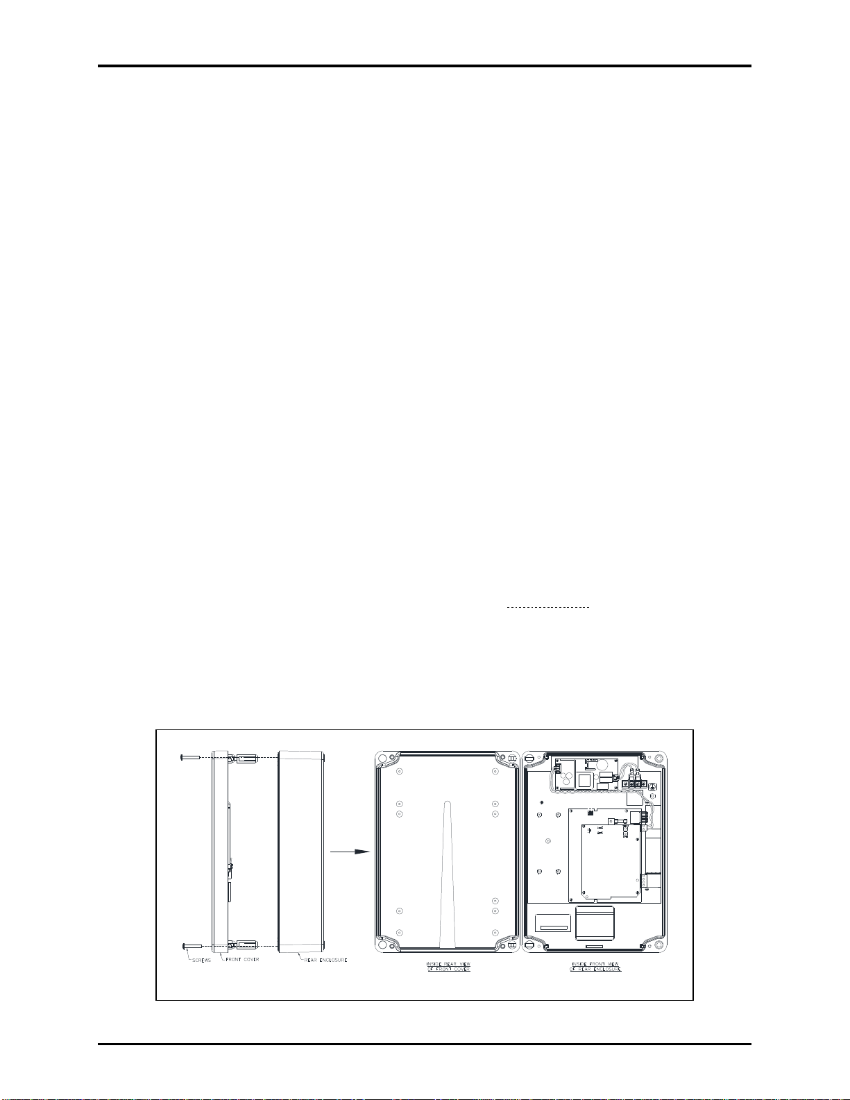
Open the VoIP Amplifier Interface.......................................................................................................5
Mount the Enclosure...............................................................................................................................6
Field Wiring.............................................................................................................................................7
Power ....................................................................................................................................................8
8-Ohm Speaker Connection..................................................................................................................9
Output Contact Connections.................................................................................................................9
Audio Output Connections....................................................................................................................9
Programming ..................................................................................................................................9
VoIP Speaker Amplifier Interface Initial Access.................................................................................9
VoIP Speaker Amplifier Interface Network Configuration................................................................9
Close the VoIP Amplifier Interface Assembly....................................................................................10
Maintenance..................................................................................................................................10
Status Indication...................................................................................................................................10
Power ..................................................................................................................................................10
Heartbeat.............................................................................................................................................10
Link.....................................................................................................................................................10
Speed...................................................................................................................................................10
VoIP Circuit PCBA Push Buttons.......................................................................................................10

Table of Contents Pub. 42004-463C
GAI-TRONICS 3030 KUTZTOWN RD. READING, PA 19605 USA
610-777-1374 ◼800-492-1212 ◼Fax: 610-796-5954
VISIT WWW.GAI-TRONICS.COM FOR PRODUCT LITERATURE AND MANUALS
Reset....................................................................................................................................................10
Factory ................................................................................................................................................ 10
USB port ................................................................................................................................................10
Amplifier Components .........................................................................................................................11
Service....................................................................................................................................................12
Reference Documentation ............................................................................................................12
Specifications ................................................................................................................................12
Electrical................................................................................................................................................12
Power......................................................................................................................................................12
Audio Output.........................................................................................................................................12
Network (Ethernet)...............................................................................................................................12
Control Outputs....................................................................................................................................12
Mechanical.............................................................................................................................................12
Environmental.......................................................................................................................................13
Approvals.......................................................................................................................................13

Pub. 42004-463C
G A I - T R O N I C S ®
A H U B B E L L C O M P A N Y
VoIP Speaker Amplifier Interface
GAI-TRONICS 3030 KUTZTOWN RD. READING, PA 19605 USA
610-777-1374 ◼800-492-1212 ◼Fax: 610-796-5954
VISIT WWW.GAI-TRONICS.COM FOR PRODUCT LITERATURE AND MANUALS
Confidentiality Notice
This manual is provided solely as an installation, operation, and maintenance guide and contains sensitive
business and technical information that is confidential and proprietary to GAI-Tronics. GAI-Tronics
retains all intellectual property and other rights in or to the information contained herein, and such
information may only be used in connection with the operation of your GAI-Tronics product or system.
This manual may not be disclosed in any form, in whole or in part, directly or indirectly, to any third
party.
Computer Software Copyrights
This product contains copyrighted computer programs stored in semiconductor memory. These programs
are copyrighted by GAI-Tronics and may not be reproduced in any form without expressed written
permission from GAI-Tronics.
General Information
Product Overview
The Model 10370-701 VoIP Speaker Amplifier Interface assembly broadcasts audio to personnel
throughout a facility over an existing network via external speaker(s) or connection to a central amplifier
speaker system. The amplifier interface is easily added to existing 10/100 BaseT Ethernet networks with
minimal cost and effort.
The VoIP speaker amplifier interface includes an integrated speaker amplifier that supplies up to 30-watts
of audio output power to an existing 8-ohm speaker or combination of speakers equaling 8 ohms. The
ability to use any speaker or horn/driver combination allows selection of speakers that meet the coverage
and environmental requirements of any specific area.
The VoIP speaker amplifier interface includes a 600-ohm, 0 dBm audio output. This output can be
connected to the audio input of a central amplifier or any equipment that requires a 600-ohm audio input.
The VoIP speaker amplifier interface also includes two dry-contact type A (normally open) outputs. Each
output is programmable for a variety of uses, such as activation of a strobe in a high noise area or
initiating a door latch remotely.
The VoIP speaker amplifier interface provides flexibility to address a diverse range of applications. A
wide variety of functions are achievable by altering the configuration data stored in the non-volatile
memory. The configuration options include:
•webpage configuration
•configuration file

Pub. 42004-463C
VoIP Speaker Amplifier Interface Page 2 of 13
P:\Standard IOMs - Current Release\42004 Instr. Manuals\42004-463C.docx
03/20
Features and Functions
GAI-Tronics’ Model 10370-701 VoIP speaker amplifier
interface has the following features:
• 10/100 BaseT Ethernet network connection
• one-way broadcasting from an IP network
• weatherproof enclosure
• 30-watt speaker amplifier (into an 8-ohm speaker load)
• 600-ohm audio output
• two dry contact relay outputs
• SIP compatible (RFC3261)
• real-time alarm reporting via SNMP, Syslog, or TMA
software
• configurable via web page or download
• multicast capability, up to eight addresses
System Requirements and Limitations
Systems containing VoIP speaker amplifier interface
assemblies require A 100 BaseT Ethernet network with a SIP
(Session Initiation Protocol) server. The operation of this equipment is limited by the customer’s LAN
media capabilities and the services available at the end point. The performance of each VoIP speaker
amplifier interface is dependent on the provision of sufficient bandwidth and network protocol
prioritization to give the quality of service required. The setup, installation, and software version of key
components, such as switches and routers, can significantly affect this equipment’s operation. Improper
connections or loose cables can also affect their operation.
The VoIP speaker amplifier interface requires a local 120/240 V ac power source for amplifier output
operation over 8 watts. PoE (Power over Ethernet) is an option for installations requiring less than 8-
watts of speaker audio output.
The following network services provide required and optional functionality (This may vary widely
depending on how the network is deployed):
• SIP proxy server (to route calls)
• SIP registrar server (frequently combined with proxy servers)
• TFTP server (for downloading configuration files).
• TCP Syslog server (for reporting alarms and external inputs)
• SNMP server (for reporting via simple network management protocol)
• SNTP server (to synchronize the internal clock)
• STUN server (for NAT firewall traversal)
• PoE (Power over Ethernet) (for less than 8-watts audio output)
Dedicated systems, such as Gatekeepers, VoIP-enabled PABXs or soft PABXs may also provide these
functions. GAI-Tronics’ VoIP speaker amplifier interface supports SIP to RFC3261 call control
signaling.
Figure 1. Model 10370-701
Outline Diagra
m

Pub. 42004-463C
VoIP Speaker Amplifier Interface Page 3 of 13
P:\Standard IOMs - Current Release\42004 Instr. Manuals\42004-463C.docx
03/20
Multicast Broadcasts
The VoIP speaker amplifier interface can receive multicast broadcasts. Multicast allows a single audio
stream to be sent to multiple end points simultaneously, achieving multi-point paging or public address
functionality over IP. Multicast requires the use of a SIP server that specifically supports multicast
functionality and each interface must be configured (enabled) to receive multicast packets.
Installation
Safety and General Information
Installation must be performed by qualified service personnel in accordance with the National
Electrical Code or applicable local codes.
Power Sources—Operate this unit only from the type of power source indicated on the label.
Contact qualified service personnel if unsure of the type of power supply to use.
•Refer to operating instructions for units intended to operate from battery power.
•Use only the recommended approved power supplies with units intended to operate with external
power supplies.
•The power source must comply with EN60950 for units intended to operate with a limited power
source. Substitutions may damage the unit or cause fire or shock.
Electromagnetic Interference/Compatibility
Electronic equipment may be susceptible to electromagnetic interference. If you experience interference,
visit the FCC website at http://www.fcc.gov for possible solutions.
Safe Handling of CMOS Integrated Circuit Devices
Many of the integrated circuit devices used in communications equipment are of the Complementary
Metal Oxide Semiconductor (CMOS) type. Because of their high open circuit impedance, CMOS
integrated circuits are vulnerable to damage from static charges. Care must be taken handling, shipping,
and servicing them and the assemblies in which they are used.
Even though protection devices are provided in CMOS integrated circuit inputs, the protection is effective
only against overvoltage in the hundreds of volts range such as is encountered in an operating system. In
a system, circuit elements distribute static charges and load the CMOS circuits, decreasing the chance of
damage. However, CMOS circuits can be damaged by improper handling of the modules, even in a
system.
To avoid damage to circuits, observe the following handling, shipping, and servicing precautions:
•Prior to and while servicing a circuit module, particularly after moving within the service area,
momentarily touch both hands to a bare metal, earth-grounded surface. This will discharge any static
charge that may have accumulated on the person doing the servicing.
NOTE:Wearing a conductive wrist strap will minimize static build-up during servicing.
•Whenever possible, avoid touching any electrically conductive parts of the circuit module with your
hands.
•Power down the unit before installing or removing the circuit module.

Pub. 42004-463C
VoIP Speaker Amplifier Interface Page 4 of 13
P:\Standard IOMs - Current Release\42004 Instr. Manuals\42004-463C.docx
03/20
•When servicing a circuit module, avoid carpeted areas, dry environments, and certain types of
clothing (silk, nylon, etc.) because they contribute to static build-up. Similarly, disconnect the test
probe prior to removing the ground lead.
•All electrically powered test equipment should be grounded. Apply the ground lead from the test
equipment to the circuit module before connecting the test probe.
•If a circuit module is removed from the system, it is desirable to lay it on a conductive surface (such
as a sheet of aluminum foil) which is connected to ground through 100-kilohms of resistance.
•When soldering, be sure the soldering iron is grounded and has a grounded tip.
•Prior to connecting jumpers, replacing circuit components, or touching CMOS pins (if this becomes
necessary in the replacement of an integrated circuit device), be sure to discharge any static build-up
as described in procedure 1. Since voltage differences can exist across the human body, it is
recommended that only one hand be used if it is necessary to touch pins on the CMOS device and
associated board wiring.
•When replacing a CMOS integrated circuit device, leave the device in its conductive rail container or
conductive foam until it is to be inserted into the printed circuit module.
•All low impedance test equipment (such as pulse generators, etc.) should be connected to CMOS
device inputs after power is applied to the CMOS circuitry. Similarly, such low impedance
equipment should be disconnected before power is turned off.
•Replacement modules shipped separately from the factory will be packaged in a conductive material.
Any modules being transported from one area to another should be wrapped in a similar material
(aluminum foil may be used). Never use non-conductive material for packaging these modules.
Important Safety Information
Install equipment without modification and according to all applicable local and national electrical codes.
Consult the National Electrical Code (NFPA 70), Canadian Standards Association (CSA 22.1), and local
codes for specific requirements regarding your installation. Class 2 circuit wiring must be performed in
accordance with the NEC.
WARNING
—This product can contain hazardous voltages. Always remove power to this
station and any associated equipment before beginning any installation.
CAUTION
—Do not install this equipment in areas other than those indicated on the approval
listing in the Approvals section of this manual. Such installation may cause a
safety hazard and consequent injury or property damage.
•Read, follow, and retain instructions—All safety and operating instructions should be read and
followed before operating the unit. Retain instructions for future reference.
•Heed warnings—Adhere to all warnings on the unit and in the operating instructions.
•Attachments—Attachments not recommended by the product manufacturer should not be used, as
they may cause hazards.
•Servicing—Do not attempt to service this unit by yourself. Opening or removing covers may expose
you to dangerous voltage or other hazards. Refer all servicing to qualified service personnel.
This permanently connected apparatus must have an ALL-POLE MAINS switch with a contact separation
of at least 3 mm in each pole incorporated in the electrical installation of the building.

Pub. 42004-463C
VoIP Speaker Amplifier Interface Page 5 of 13
P:\Standard IOMs - Current Release\42004 Instr. Manuals\42004-463C.docx
03/20
Cable Installation Safety Considerations
Interconnecting communication and Class 2 dc power cables should be separated from electrical light or
other Class 1 circuits by at least 2 inches. The exception is where Class 1 wiring or power circuits are run
in a raceway, or are metal-sheathed or metal-clad, or are permanently separated from the conductors of
the other circuitry by a continuous and firmly fixed nonconductor such as porcelain tubes or flexible
tubing in addition to the insulation on the wire. Communications cables and in-building wiring should be
listed and marked for the purpose according to NEC Article 800.
Outdoor Product
Power Lines—Do not locate this product in the vicinity of overhead power lines, electric lights, power
circuits, or where it may contact such power lines or circuits, as this contact might be fatal. Refer to the
National Electrical Code, Article 800, regarding installation.
Mechanical Receipt Inspection
The speaker amplifier interface is shipped in a cardboard container, protected from movement and
distress by a self-forming packaging material. Thoroughly inspect it as soon as possible after delivery.
Immediately report in-transit damage to the transportation company.
Required Tools
• #1 Phillips screwdriver
• 1/16-inch flat blade screwdriver (for TB101, TB1 and TB3 connections only)
Open the VoIP Amplifier Interface
The VoIP speaker amplifier interface must be opened for programming and installation.
NOTE: Bench programming and testing is recommended (see the Programming section).
1. Remove the assembly from the carton and position it on a flat surface with the front of the unit facing
up.
2. Loosen the four screws, located at the four corners of the front cover.
3. Open the enclosure’s front cover to the left.
Figure 2: VoIP Amplifier Interface Assembly

Pub. 42004-463C
VoIP Speaker Amplifier Interface Page 6 of 13
P:\Standard IOMs - Current Release\42004 Instr. Manuals\42004-463C.docx
03/20
Mount the Enclosure
1. Pull on the left side of the enclosure until the hinge pins pull loose to separate the front and rear
sections (see Figure 2). Set the front of the enclosure aside.
2. Determine the conduit or cable gland location on the rear enclosure.
Drill spots are on the top and bottom for use with either a chassis punch or hole saw (bottom entry is
recommended).
3. Cut or punch the appropriate size hole(s) in the enclosure.
4. Connect the hub(s) to the conduit before connection to the enclosure.
Use Myers ST-4 (1.25-inch) Scru-Tite® hubs or equivalent. (Scru-Tite is a registered trademark of
Crouse-Hinds, Inc.)
5. Secure the rear enclosure to the wall with screws or appropriate fasteners (see Figure 3).
The enclosure’s mounting holes are 0.280 inches in diameter.
Figure 3. VoIP Amplifier Interface Component Identification

Pub. 42004-463C
VoIP Speaker Amplifier Interface Page 7 of 13
P:\Standard IOMs - Current Release\42004 Instr. Manuals\42004-463C.docx
03/20
Field Wiring
WARNING
—Do not apply power until all the connections are wired.
Consult the National Electrical Code (NFPA 70), Canadian Standards Association (CSA 22.1), and local
codes for the specific requirements regarding your installation. Install all equipment without modification
and according to the local and national codes. Class 2 circuit wiring must be performed in accordance
with the NEC
1. Route the ac power, speaker, input/output, and Ethernet cable through conduit and into the enclosure.
Allow adequate cable length to access the terminal blocks.
2. Secure loose cabling.
3. Install all connections as indicated in the following subsections (see Table 1, Table 2, Figure 4, and
Figure 5 for wiring details).
Table 1. Recommended Cable
Cable Use
Recommended Size
Conductor Range
LAN
Category 5 or better UTP cable with an RJ45 connector
Power
two-conductor, No. 18 AWG is typical
No. 28–12 AWG
Speaker
two-conductor, twisted pair, No. 18 AWG is typical
No. 30–12 AWG
600-ohm audio
two-conductor, twisted pair, No. 22 AWG is typical
No. 28–20 AWG
Output contacts
two or three-conductor, No. 18 AWG is typical
No. 28–20 AWG
Table 2. Customer Terminations
Cable
Terminals
Function
LAN
RJ45 Jack (on VoIP PCBA)
Power
TB101-1
TB101-2
GROUND STUD
Hot
Neutral
Earth
Speaker
TB3-1
TB3-2
Speaker +
Speaker −
600-ohm audio
line out
TB1-1
TB1-8
Audio L2
Audio L1
Isolate relay
Opto-coupler
TB3-3
TB3-4
TB1-7
TB1-14
Out 1 C
Out 1 N.O.
Out 2 N.O.
Out 2 C
NOTE:Out 1 and Out 2 are configurable for one of two modes of operation: Direct call or Multicast

Pub. 42004-463C
VoIP Speaker Amplifier Interface Page 8 of 13
P:\Standard IOMs - Current Release\42004 Instr. Manuals\42004-463C.docx
03/20
Power
Ground
The unit must be connected to earth ground:
1. Install a #6 ring lug on the incoming ground wire.
2. Secure the ground conductor to the ground stud, located in the upper right corner of the housing.
PoE (Power over Ethernet)
The device can be powered from the network cable if the speaker output requirement is less than 8 watts.
PoE works across standard network cabling (i.e. Cat5) to supply power directly from the data ports where
the device is connected.
Connect the LAN cable (Category 5 or better UTP cable) to the RJ45 jack, located on the underside of the
VoIP interface PCBA (see Figure 4).
Local Power
The device requires a 120/240 V ac power source if the speaker output requirement is greater than 8
watts.
1. Install spade lugs on the power line conductors.
2. Connect the power conductors to terminal block TB101, located in the upper right corner of the
housing (see Figure 4).
Figure 4. Field Wiring Connections

Pub. 42004-463C
VoIP Speaker Amplifier Interface Page 9 of 13
P:\Standard IOMs - Current Release\42004 Instr. Manuals\42004-463C.docx
03/20
8-Ohm Speaker Connection
Connect an 8-ohm speaker to removable terminal block TB3 terminals 1and 2(see Figure 4).
Output Contact Connections
Two relay contact sets are available on connectors TB3 and TB1. Each contact set is form A type NO
(normally open) (see Figure 4).
Audio Output Connections
Connect the 600-ohm audio output wiring to connector TB1, terminals 1and 8(see Figure 4).
Programming
NOTE:The Model 10370-701VoIP Speaker Amplifier Interface includes the same embedded browser as
GAI-Tronics’ VoIP and VoIP WiFi telephones. There are many programmable parameters
utilized by our telephones that are not utilized by the VoIP speaker amplifier interface. All
amplifiers are factory programmed for maximum operating proficiency. Do not make any
programming changes other than those directed in this manual.
VoIP Speaker Amplifier Interface Initial Access
1. Connect a PC to the same network as the VoIP speaker amplifier interface.
2. Log into the unit’s web interface.
The unit is factory configured with a static IP address: 192.168.1.2.
3. Enter the username and password when prompted.
The initial factory settings are:
•USER NAME: user
•PASSWORD: password
4. Change the username and password upon first login.
This security measure helps prevent unauthorized changes to the VoIP telephone’s interface
configuration.
VoIP Speaker Amplifier Interface Network Configuration
Configure each VoIP speaker amplifier interface for operation on the network prior to installation.
Assign a local ID, domain, proxy, and registrar.
1. Assign a host name.
Host names provide identification of different VoIP PCBAs on the network.
2. Test that calls can be made successfully.
3. Maintain the speaker amplifier interface by monitoring alarms.
4. Set up auto-updates.
Refer to Pub. 42004-548 for basic configuration instructions for these VoIP devices (see the Service
Contact a regional service center for an RA# (return authorization number) if the equipment requires
service. Equipment must be shipped prepaid to GAI-Tronics with an RA# and a purchase order number.

Pub. 42004-463C
VoIP Speaker Amplifier Interface Page 10 of 13
P:\Standard IOMs - Current Release\42004 Instr. Manuals\42004-463C.docx
03/20
Repairs or a replacement will be made in accordance with GAI-Tronics’ warranty policy if the equipment
is under warranty. Please include a written explanation of all defects to assist our technicians in their
troubleshooting efforts. Call 800-492-1212 inside the USA or 610-777-1374 outside the USA for help
identifying the nearest regional service center.
Reference Documentation section).
Close the VoIP Amplifier Interface Assembly
1. Assemble the front and rear sections.
2. torque the front panel screws to 16 to 20 in·lb.
Maintenance
Status Indication
Power
The ON LED, located on the VoIP PCBA (see Figure 5), illuminates when power is applied to the
telephone.
Heartbeat
The HB LED, located on the VoIP PCBA (see Figure 5), flashes when communication over the LAN is
established.
Link
The LNK LED, located on the VoIP PCBA (see Figure 5), indicates an active network connection when
illuminated.
Speed
The SP LED, located on the VoIP PCBA (see Figure 5), indicates a 100 Mbps network connection when
illuminated or a 10 Mbps connection when off.
VoIP Circuit PCBA Push Buttons
Reset
Press the RESET button momentarily to warm reboot the telephone (see Figure 5). The telephone
maintains the current configuration.
Factory
Use the FACTORY button (see Figure 5) to erase the current configuration and restore the factory default
settings:
3. Press and release the RESET button.
4. Press and hold the FACTORY button for 10 seconds while the telephone is rebooting.
The telephone will reboot again with the factory default settings configured.

Pub. 42004-463C
VoIP Speaker Amplifier Interface Page 11 of 13
P:\Standard IOMs - Current Release\42004 Instr. Manuals\42004-463C.docx
03/20
USB port
The USB port is for GAI-Tronics service personnel only. Make no connection to this port.
Figure 5. VoIP PCBA—Component Locations
Amplifier Components
The Model 10370-701 VoIP Speaker Amplifier Interface contains the following components:
Table 3. Models 10370-701 Replacement Parts
Part No. Description
69625-001 VoIP Carrier PCBA
100-02-7013-000 VoIP Interface PCBA

Pub. 42004-463C
VoIP Speaker Amplifier Interface Page 12 of 13
P:\Standard IOMs - Current Release\42004 Instr. Manuals\42004-463C.docx
03/20
Service
Contact a regional service center for an RA# (return authorization number) if the equipment requires
service. Equipment must be shipped prepaid to GAI-Tronics with an RA# and a purchase order number.
Repairs or a replacement will be made in accordance with GAI-Tronics’ warranty policy if the equipment
is under warranty. Please include a written explanation of all defects to assist our technicians in their
troubleshooting efforts. Call 800-492-1212 inside the USA or 610-777-1374 outside the USA for help
identifying the nearest regional service center.
Reference Documentation
VoIP Basic Configuration Guide...................................................................................................42004-548
VoIP Firmware Programming Guide.................................................................................. 502-20-0171-001
Specifications
Electrical
Power
AC:
Input voltage.......................................................................................................... 120/240 V ac, 50/60 Hz
Input current....................................................................................0.35 A @ 120 V ac, 0.2 A @ 240 V ac
PoE
Power.............................................................................................................802.3af compliant (via RJ45)
Audio Output
Speaker output power:
With PoE.............................................................................................................8 W into 8-Ωload, or
With 120/240 V ac input................................................................................... 30 W into 8-Ω load, or
Line out (into 600 ohms).................................................................................................................1.0 V RMS
Frequency response.................................................................................................................300–3000 Hz
Network (Ethernet)
Signaling.......................................................................................SIP (RFC3261 compliant) loose routing
Addressing..................................................static IP provisioning or DHCP STUN client (NAT traversal)
Configuration.............................................................................................................embedded web server
.........................................................................................................................configuration file download
...................................................................................................SNTP with time zone and daylight saving
.......................................................................................................................automatic updating via TFTP
..................................................................................................................................... password protection
Control Outputs
Output 1 (isolated solid-state switch).................................................50 mA @ 30 V ac/dc (resistive load)
Output 2 (isolated SPST relay) .............................................................10 A @ 30 V ac/dc (resistive load)
Mechanical
Physical dimensions...............................................13.00 H × 9.25 W × 4.00 D in; (330 × 235 × 102 mm)
Enclosure material .........................................................................high-impact, glass-reinforced polyester
Connections...................................................................................... four drill spots for location of conduit

Pub. 42004-463C
VoIP Speaker Amplifier Interface Page 13 of 13
P:\Standard IOMs - Current Release\42004 Instr. Manuals\42004-463C.docx
03/20
Mounting........................................................................surface-mounting: four 0.28-inch mounting holes
Color ..................................................................................................................................................... gray
Shipping weight...................................................................................................................6.0 lb (2.72 kg)
Environmental
Temperature range:
Operating......................................................................................−4 ºF to +131 ºF (−20 ºC to +55 ºC)
Storage.........................................................................................−40 ºF to 158 ºF (−40 ºC to +70 ºC)
Weatherproof rating.......................................................................................................................rainproof
Humidity...........................................................................................................up to 95%, non-condensing
Approvals
USA ..............................................................FCC Modular Approval, FCC ID: FCC ID: XM5-SM2144N1
CFR Title 47 FCC Part 15, Subpart B and C
Canada ...............................................................Industry Canada Module Approval IC: 8516A-SM2144N2
Industry Canada ICES-003, RSS-Gen, RSS-210
EU.............................................................................................EN 300 328 (R&TTE Directive 1999/5/EC)
EN 301 489 (EMC Directive 2004/108/EC)
User Instructions (USA)
This equipment has been tested and found to comply with the limits for a Class A digital device, pursuant to part 15
of the FCC Rules. These limits are designed to provide reasonable protection against harmful interference when the
equipment is operated in a commercial environment. This equipment generates, uses, and can radiate radio
frequency energy and, if not installed and used in accordance with the instruction manual, may cause harmful
interference to radio communications. Operation of this equipment in a residential area is likely to cause harmful
interference in which case the user will be required to correct the interference at his own expense.

(Rev. 10/06)
Warranty
Equipment. GAI-Tronics warrants for a period of one (1) year from the date of shipment, that any
GAI-Tronics equipment supplied hereunder shall be free of defects in material and workmanship, shall
comply with the then-current product specifications and product literature, and if applicable, shall be fit
for the purpose specified in the agreed upon quotation or proposal document. If (a) Seller’s goods prove
to be defective in workmanship and/or material under normal and proper usage, or unfit for the purpose
specified and agreed upon, and (b) Buyer’s claim is made within the warranty period set forth above,
Buyer may return such goods to GAI-Tronics nearest depot repair facility, freight prepaid, at which time
they will be repaired or replaced, at Seller’s option, without charge to Buyer. Repair or replacement shall
be Buyer’s sole and exclusive remedy. The warranty period on any repaired or replacement equipment
shall be the greater of the ninety (90) day repair warranty or one (1) year from the date the original
equipment was shipped. In no event shall GAI-Tronics warranty obligations with respect to equipment
exceed 100% of the total cost of the equipment supplied hereunder. Buyer may also be entitled to the
manufacturer’s warranty on any third-party goods supplied by GAI-Tronics hereunder. The applicability
of any such third-party warranty will be determined by GAI-Tronics.
Services. Any services GAI-Tronics provides hereunder, whether directly or through subcontractors,
shall be performed in accordance with the standard of care with which such services are normally
provided in the industry. If the services fail to meet the applicable industry standard, GAI-Tronics will re-
perform such services at no cost to buyer to correct said deficiency to Company's satisfaction provided
any and all issues are identified prior to the demobilization of the Contractor's personnel from the work
site. Re-performance of services shall be Buyer's sole and exclusive remedy, and in no event shall GAI-
Tronics warranty obligations with respect to services exceed 100% of the total cost of the services
provided hereunder.
Warranty Periods. Every claim by Buyer alleging a defect in the goods and/or services provided
hereunder shall be deemed waived unless such claim is made in writing within the applicable warranty
periods as set forth above. Provided, however, that if the defect complained of is latent and not
discoverable within the above warranty periods, every claim arising on account of such latent defect shall
be deemed waived unless it is made in writing within a reasonable time after such latent defect is or
should have been discovered by Buyer.
Limitations / Exclusions. The warranties herein shall not apply to, and GAI-Tronics shall not be
responsible for, any damage to the goods or failure of the services supplied hereunder, to the extent
caused by Buyer’s neglect, failure to follow operational and maintenance procedures provided with the
equipment, or the use of technicians not specifically authorized by GAI-Tronics to maintain or service the
equipment. THE WARRANTIES AND REMEDIES CONTAINED HEREIN ARE IN LIEU OF AND
EXCLUDE ALL OTHER WARRANTIES AND REMEDIES, WHETHER EXPRESS OR IMPLIED BY
OPERATION OF LAW OR OTHERWISE, INCLUDING ANY WARRANTIES OF
MERCHANTABILITY OR FITNESS FOR A PARTICULAR PURPOSE.
Return Policy
If the equipment requires service, contact your Regional Service Center for a return authorization number
(RA#). Equipment should be shipped prepaid to GAI-Tronics with a return authorization number and a
purchase order number. If the equipment is under warranty, repairs or a replacement will be made in
accordance with the warranty policy set forth above. Please include a written explanation of all defects to
assist our technicians in their troubleshooting efforts.
Call 800-492-1212 (inside the USA) or 610-777-1374 (outside the USA) for help identifying the
Regional Service Center closest to you.
Table of contents
Other Hubbell Recording Equipment manuals
Popular Recording Equipment manuals by other brands

Akai
Akai APC Key 25 user manual

Alpine
Alpine PXE-H650 - System Integration Audio... Setup guide

Innovative Technology
Innovative Technology ITRR-501 instructions

Hughes & Kettner
Hughes & Kettner Warp Factor manual

Kidde
Kidde SA-ETH Installation sheet

NEXIQ Technologies
NEXIQ Technologies Blue-Link Installation and setup manual