manuals.online logo
Brands
  1. Home
  2. •
  3. Brands
  4. •
  5. Hubbell
  6. •
  7. Switch
  8. •
  9. Hubbell CXSW User manual

Hubbell CXSW User manual

CXSW
INSTALLATION GUIDE
3319B 062218
701 Millennium Blvd. | Greenville, SC 29607 | (864) 678-1000 | (866) 898-0131 - fax www.hubbellcontrolsolutions.com
Copyright © 2018 Hubbell Control Solutions, a division of Hubbell Lighting, Inc. All rights reserved. All product and company names,
logos and product identiers are trademarks ™ or registered trademarks ® of Hubbell Lighting, Inc. or their respective owners.
Use of them does not necessarily imply any aliation with or endorsement by such respective owners.
72-00547B
PRECAUTIONS
• CAUTION: Class 2, low voltage device, do not use with Line voltage.
• Read and understand all instructions prior to installation.
• Use only approved materials and components (i.e. wire nuts, electrical boxes, etc.) as appropriate for installation.
• Do not install if product appears to be damaged.
• In retrot application, all excess cable MUST be removed from wall box prior to installation. Connection between Cat5e/6 cable and switch
station port must be straight and true without interference or pressure from excess or misaligned cable.
• Prior to programming of the CX panel/switch stations, all Cat5e/6 cables must be tested to ensure no breaks or cross connections exist on the
category cable and/or RJ45 connectors.
• SAVE THESE INSTRUCTIONS!
DESCRIPTION
Hubbell Control Solutions’ (HCS), CX series switch stations (CXSW), are intended solely for use with the CX series lighting control panel, utilizing the
dimming option card (CXDIMCONTRBD). The CXSW switches not only have the capacity to control relays, groups and presets, they also have the
ability to be programmed to provide continuous manual dimming. Flexible, programmable congurations of the buttons allow the user to “move”
control points to other buttons if desired. Both the switch station and the CX panel require programming.
SPECIFICATIONS
• Class 2, low voltage device
• 2-RJ45 ports located on the rear of the station
• Indoor use only
• Operating temperature: 32°to 122°F (0° to 50°C), Relative humidity (non-condensing): 10% to 90%
• Requires: 10mA@30VDC Max
• Dimensions: 4.3” L x 1.13” W x 1.13” D
• Weight: 1.6oz
INSTALLATION
1. Prepare the installation site as necessary. Switches may be installed in a single gang box or ganged into a multi-gang box.
2. Switches can be daisy chain wired in series using a Cat5e/6 cable with RJ45 connectors. Since the Dimming Card has only 4 total switch input
connectors, some installations will require switches to be daisy chained in order to achieve the desired functionality. Plan ahead before running
the category cables for the switches. See examples on page 2.
3. Plug in a Hubbell Cat5e/6 series or a standard Cat5e/6 category cable into either connector on the back of the switch. Remove excess wire from
the box so that undo pressure is not exerted on the switch when it is inserted into the box.
4. Plug the other end of the cable into an appropriate RJ45 port on the Dimming Option Card in the CX panel or to the next daisy chained CX
switch station.
5. For ganging two or more switches in one switch box, use the Hubbell 3” Cat5 jumper cable supplied in the packaging of the switch station.
All RJ45 ports located on the back of the switch stations run in parallel and either one can be an in or an out.
6. Do not install a cover plate on the switch until it has been programmed.
7. For installation of the CXSW switch station beyond 300ft please consult with HCS Technical Services. (800)-888-8006
PROGRAMMING THE SWITCH
The process of programming the switch is simple and straight forward. It does not require any special tools or software. The actual lighting control
features to be performed by each button will be programmed at the CX panel. There are 6 control lines (wires) physically in the Cat5 cable used with
the switch. The switch programming simply determines which of the 6 lines (A - F) that the button will aect when pressed.
1. The switch must be properly connected to the CX panel Dimming Option card and the panel must be powered up to program the switch.
2. Carefully remove the plastic switch bezel that surrounds the buttons. Use a small screw driver or similar to pry the bezel from the bottom of the
switch housing using the detent in the housing at the bottom of the bezel. See Figure 1.
3. Locate the cong (programming) button along the right side of the printed circuit board near the center.
4. Gently remove button caps to have access to the cong button and visually conrm LED status programming. See Figure 2.
5. Locate an array of 6 LEDs on the printed circuit board above the cong button. While not physically labeled, these represent lines A - F
beginning with A at the top. See Figure 2.
6. Press and release the cong button. All 6 LEDs will begin to blink.
7. Press one of the control buttons. Note that only one of the LEDs will be illuminated. Tap the control button to advance the position of the
illuminated LED. Stop when the LED representing the desired control line A - F is illuminated. Repeat for each button on the station.
8. Press the cong button for 2 seconds to exit the programming mode and save the program.
9. After completing the programming and exiting the program mode, press each control button and observe that the proper LED indicator
illuminates when the button is pressed.
1
CXSW
INSTALLATION GUIDE
3319B 062218
701 Millennium Blvd. | Greenville, SC 29607 | (864) 678-1000 | (866) 898-0131 - fax www.hubbellcontrolsolutions.com
Copyright © 2018 Hubbell Control Solutions, a division of Hubbell Lighting, Inc. All rights reserved. All product and company names,
logos and product identiers are trademarks ™ or registered trademarks ® of Hubbell Lighting, Inc. or their respective owners.
Use of them does not necessarily imply any aliation with or endorsement by such respective owners.
72-00547B
10. If the button does not control the proper line when pressed, repeat the programming process above.
11. Some switch models are supplied with alternate button caps for use with various functions. To change the button cap, carefully pull the button
cap straight o the switch. Do not twist or ex the button shaft. Carefully press the new button cap onto the shaft.
12. Re-install the switch bezel by inserting the top tabs into the slots in the housing then press the lower tabs into their slots. Note that the
openings and legends around the edges of the bezel are not used on this assembly and have no function.
13. Install a standard face plate on the switch (not supplied).
14. Complete the programming of the CX panel per the project requirements.
PROGRAMMING NOTES
Notes:
1. There can only be 6 Control Points per RJ45 port per dimming card, (A, B, C, D, E, and F)
2. By default a CXSW-1 is an A control point, a CXSW-2 rst button is an A and second button is a B control point.
3. Dimmer Inputs are congured in the Dimmer Inputs section of programming.
4. Dimming channels and Dimmer inputs must not share the same control point.
5. Switch types are dened as On, O, Toggle, Preset, Raise and Lower.
6. Buttons can be programmed to any switch type.
7. Wall station button control points can recongured using the cong button located under the bezel. See Programming the Switch
section on page 1
Examples:
1. A 6-button switch station would occupy all 6 control points from the RJ45 port it is connected. Any additional switch stations daisy chained
from this or to this 6-button station would function to provide 3-way support functionality.
2. A 4-button and a 2-button switch station connected in a daisy chain fashion from the same RJ45 port but performing separate controls would
occupy all 6 control points. Any additional switch stations daisy chained from this or to this 6-button station would function to provide 3-way
support functionality.
3. Six 1-button switch stations daisy chained o a single RJ45 port would be able to accommodate 6 unique switch types. Any additional daisy
chained switch stations would serve as 3-way buttons to the original programmed stations.
4. If you want to utilize a 4-button CXSW station to perform On, Raise, Lower and O, (ORLO) then you should use 4 control points and are only
capable of programming 2 more actions. (i.e. you can only use 1 ORLO on that RJ45 port). Any additional daisy chained switch stations would
serve as 3-way buttons to the original programmed stations.
5. To provide individual on/o and dimming control of all eight dimming channels on a single dimming card requires using eight 3-button
switches with two daisy-chained on each RJ45port.
2
CXSW
INSTALLATION GUIDE
3319B 062218
701 Millennium Blvd. | Greenville, SC 29607 | (864) 678-1000 | (866) 898-0131 - fax www.hubbellcontrolsolutions.com
Copyright © 2018 Hubbell Control Solutions, a division of Hubbell Lighting, Inc. All rights reserved. All product and company names,
logos and product identiers are trademarks ™ or registered trademarks ® of Hubbell Lighting, Inc. or their respective owners.
Use of them does not necessarily imply any aliation with or endorsement by such respective owners.
72-00547B
PROGRAMMING LOGIC TO FOLLOW
A button can perform a non-dimming action as a Dimmer Input. A button can only perform one action, whether On, O, Toggle, Preset or a Raise or
Lower Action.
CXSW Button Dimmer Input Control Points (A, B, C, D, E, F)
CXSW 12346
Dimmer Input Switch Types
On, O, Toggle, Preset On, O, Toggle, Preset On, O, Toggle, Preset On, O, Toggle, Preset On, O, Toggle, Preset
On, O, Toggle, Preset On, O, Toggle, Preset On, O, Toggle, Preset On, O, Toggle, Preset
On, O, Toggle, Preset On, O, Toggle, Preset On, O, Toggle, Preset
On, O, Toggle, Preset On, O, Toggle, Preset
On, O, Toggle, Preset
A button can perform manual continuous dimming; however the raise/lower functions are static to the control point association, A can only be a
Raise. The A control point can be on the rst button or the second button or the third button and so on. It is user dened.
CXSW Dimmer Congurations Control Points (Raise/Lower sw)
A B C D E F
Raise Lower Raise Lower Raise Lower
A + B are always associated raise/lower switches.
C + D are always associated raise/lower switches.
E + F are always associated raise/lower switches.
3

Other Hubbell Switch manuals

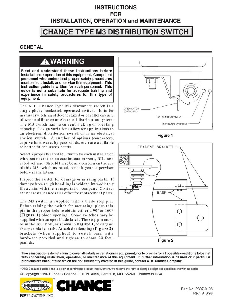
Hubbell CHANCE M3 Installation and operating instructions

Hubbell

Hubbell CHANCE M3 Installation and operating instructions

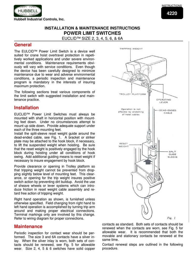
Hubbell M3 Programming manual

Hubbell

Hubbell M3 Programming manual

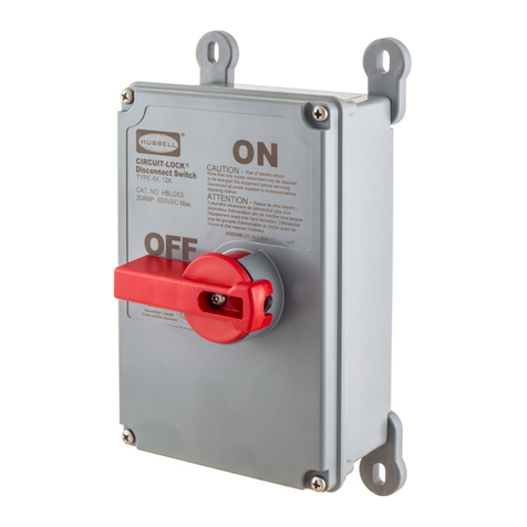
Hubbell CIRCUIT-LOCK Series Configuration guide

Hubbell

Hubbell CIRCUIT-LOCK Series Configuration guide

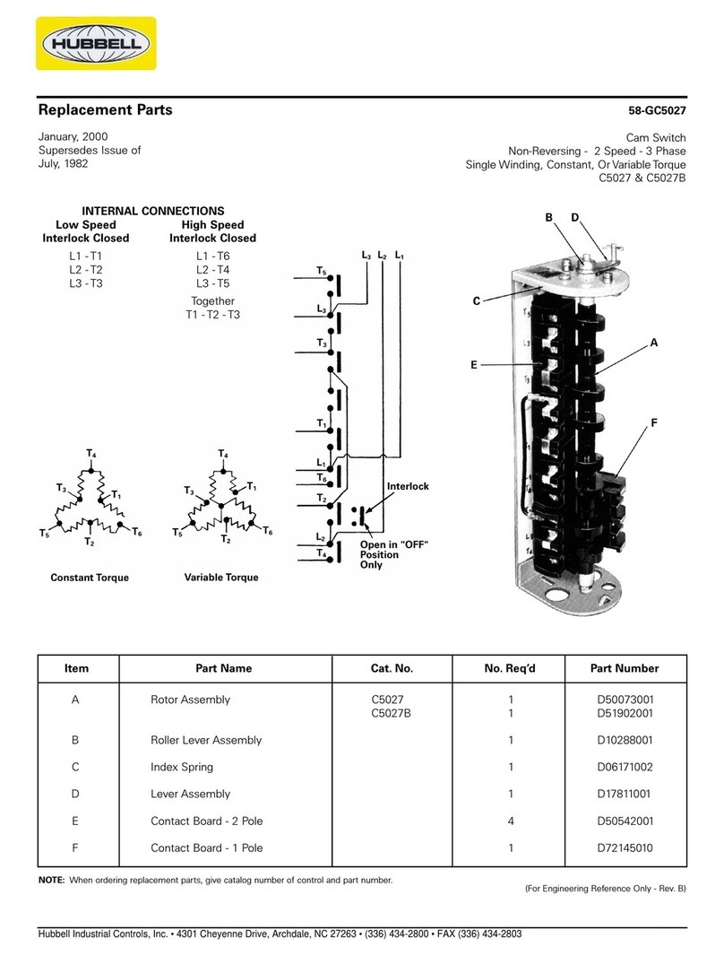
Hubbell C5027 Manual

Hubbell

Hubbell C5027 Manual

Hubbell 2200 User manual

Hubbell

Hubbell 2200 User manual

Hubbell Circuit-Lock User manual

Hubbell

Hubbell Circuit-Lock User manual

Hubbell CIRCUIT-LOCK User manual

Hubbell

Hubbell CIRCUIT-LOCK User manual

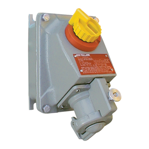
Hubbell Killark VWSQ Series Instruction Manual

Hubbell

Hubbell Killark VWSQ Series Instruction Manual

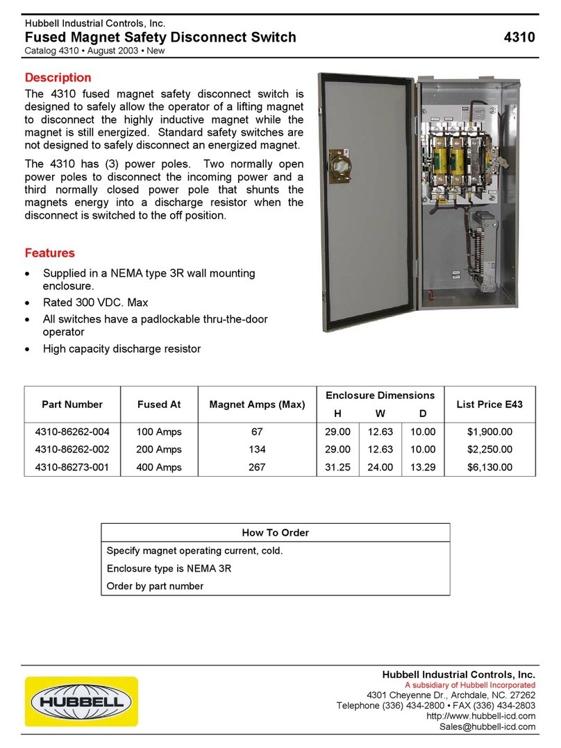
Hubbell 4310 Manual

Hubbell

Hubbell 4310 Manual

Hubbell iDevices IDEVZ01DW User manual

Hubbell

Hubbell iDevices IDEVZ01DW User manual

Hubbell Euclid 100E User manual

Hubbell

Hubbell Euclid 100E User manual

Hubbell LUXSTATSW1 User manual

Hubbell

Hubbell LUXSTATSW1 User manual

Hubbell Euclid 4220 User manual

Hubbell

Hubbell Euclid 4220 User manual

Hubbell Euclid PBP Pendant User manual

Hubbell

Hubbell Euclid PBP Pendant User manual

Hubbell RDS50Z User manual

Hubbell

Hubbell RDS50Z User manual

Hubbell LVS1HD Operating instructions

Hubbell

Hubbell LVS1HD Operating instructions

Hubbell Furnas Brand Series 54 User manual

Hubbell

Hubbell Furnas Brand Series 54 User manual

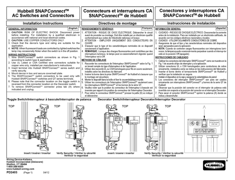
Hubbell SNAPConnect Series User manual

Hubbell

Hubbell SNAPConnect Series User manual

Hubbell Euclid 4225 User manual

Hubbell

Hubbell Euclid 4225 User manual

Hubbell H-MOSS AP User manual

Hubbell

Hubbell H-MOSS AP User manual

Hubbell Limit Switches User manual

Hubbell

Hubbell Limit Switches User manual

Hubbell 2210 User manual

Hubbell

Hubbell 2210 User manual

Hubbell 2243 User manual

Hubbell

Hubbell 2243 User manual

Hubbell WL Series User manual

Hubbell

Hubbell WL Series User manual

Popular Switch manuals by other brands

3Com SUPERSTACK 3 3870 Series Getting started guide

3Com

3Com SUPERSTACK 3 3870 Series Getting started guide

Extron electronics System 10 Plus user manual

Extron electronics

Extron electronics System 10 Plus user manual

SOR 1550 General instructions

SOR

SOR 1550 General instructions

Extron electronics mediaport 200 Setup guide

Extron electronics

Extron electronics mediaport 200 Setup guide

Azbil FL7M Series manual

Azbil

Azbil FL7M Series manual

Belkin OmniView F1DD102U Quick installation guide

Belkin

Belkin OmniView F1DD102U Quick installation guide

Edge-Core AGR420 quick start guide

Edge-Core

Edge-Core AGR420 quick start guide

Aivee Edition one HD user manual

Aivee

Aivee Edition one HD user manual

LEGRAND adorne WNAL33 quick start guide

LEGRAND

LEGRAND adorne WNAL33 quick start guide

Smartwares SH4-99572 instruction manual

Smartwares

Smartwares SH4-99572 instruction manual

Owon SLC600-D quick start guide

Owon

Owon SLC600-D quick start guide

ZIV SW3-L3 user guide

ZIV

ZIV SW3-L3 user guide

Atrust m320 Setup guide

Atrust

Atrust m320 Setup guide

Modcan Euro Quad LFO user guide

Modcan

Modcan Euro Quad LFO user guide

Ultra Products ULT31807 Specification sheet

Ultra Products

Ultra Products ULT31807 Specification sheet

NETGEAR ProSafe GSM5212P Installationsanleitung

NETGEAR

NETGEAR ProSafe GSM5212P Installationsanleitung

3Com WX3000 Series Operation manual

3Com

3Com WX3000 Series Operation manual

Kramer VS-34FD user manual

Kramer

Kramer VS-34FD user manual

manuals.online logo
manuals.online logoBrands
  • About & Mission
  • Contact us
  • Privacy Policy
  • Terms and Conditions

Copyright 2025 Manuals.Online. All Rights Reserved.