SENKO iGas Detector CO2 User manual

Portable Single Gas Detector
User’s Manual

The iGas Detector CO₂is a portable single gas detector designed to detect the presence
of carbon dioxide gas in ambient environment. When activated, iGas Detector CO₂
continuously monitors ambient air for the presence of carbon dioxide gas and alerts the
user to potentially unsafe exposure with LED, vibrating, and audible alarms in the event
that gas concentration exceeds alarm setpoints. The settings value can be adjusted
manually or by connecting to a PC software.
•Any unauthorized attempt to repair or modify the product, or any other cause of
damage beyond the range of the intended use, including damage by fire, lightening,
or other hazard, voids liability of the manufacturer.
•Activate this product only if sensor, visual, detection, and audible cover are clear
from contaminants such as dirt and debris that could block the area where gas is to
be detected.
•Do not clean and rub the LCD screen of the products with a dry cloth or hands in
hazardous environment to prevent the static electricity.
•Perform cleaning and maintenance of the products in fresh air that is free of
hazardous gases
•Test the response of a sensor regularly by the gas concentration exceeding alarm set
points.
•Test LED, audio and vibration manually.
•If the temperature changes sharply during use of the device (e.g., indoors vs
outdoors), the value of the measured gas concentration can suddenly change.
Please use the detector after the gas concentration value has stabilized.
•Severe vibration or shock to the device may cause a sudden reading change. Please
use detector after the value of gas concentration has stabilized. Excessive shock to
the detector can cause the device and/or sensor to malfunction.
•Alarm value should be set based on the international standard. Therefore, alarm
values should be changed only under the responsibility and approval of the
administration of the work site where the instrument is used.
•Use IR communications in the safety zone which is free of hazardous gases.
•Replace the battery and sensor in clean environment, which is free of hazardous gas.
•If the CO2 concentration reaches 0ppm, the calibration should be performed.
WARNING
•Before operating this device, please read the manual carefully.
•This device is not an analyzer, but a gas detector.
•If calibration and self-test fails continuously, please do not use the device.
•Clean detectors with a soft cloth and do not use chemical substances for cleaning.
CAUTION
Product Overview

1. LCD and Part Description
2. Activation & Deactivation
3. Mode
3.1. Measuring Mode
3.2. Display Mode
4. Setting Mode
4.1.Alarm & Adjust alarm setpoints
4.2. Calibration
4.3. Clr max
5. Software Manager
6. Maintenance
4
5
6
8
9
10
11
13
16
7. Specification 18
8. Battery Charging 18
3.3. Menu Tree 7
4.4. Clr STEL and TWA
4.5.Adjust Unit 12
4.6. Factory Reset
4.7. Self Test
….……………………
….……………………
...………..….………………………
.…………..….………………………
………………
...………..….………………………
....…………..….………………………
...….………………………
….……..…………..….………………………
…………..….…………………
............………….......………………
…………..…………..………………
.....…..….………………………
2.1. Bump test
Table Contents
9. Warranty 19
…….…………..….………………………
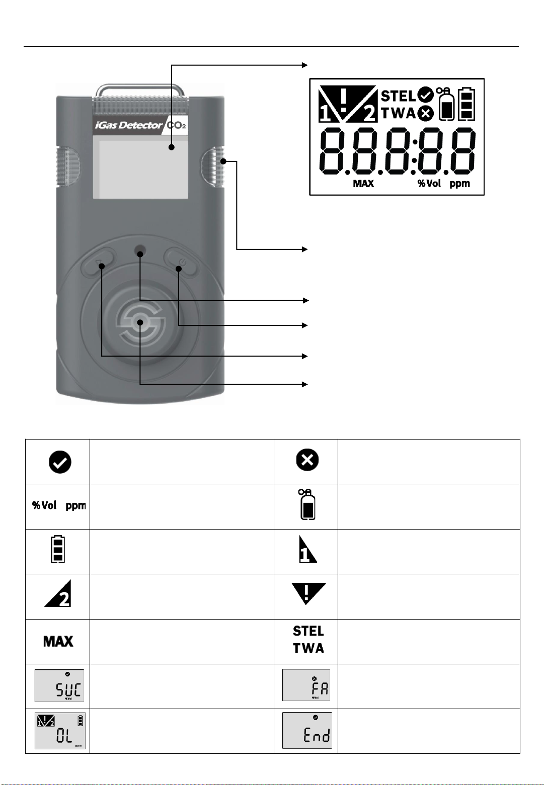
Calibration /
Setting Success Calibration /
Setting Failure
Measurement Unit Standard Gas Calibration
Remaining Battery 1st Alarm Display
2nd Alarm Display Alarm Condition
Max Value Short Term Exposure Limit
Time WeightedAverage
Test Success Test Fail
Over Limit End of Test
Part Description
LCD display
Alarm LED
Buzzer
Power Button
Gas sensor
4
Push Button
1. LCD and Part Description
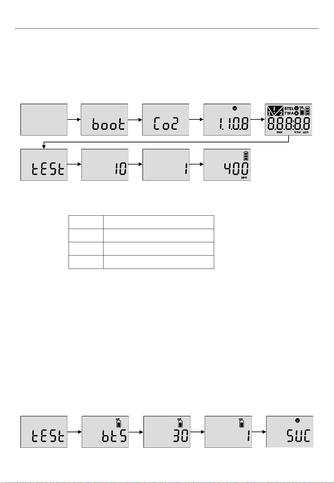
1. Move to a fresh air environment, which is free of hazardous gas
2. Press and hold down the power button for approximately 2 seconds until the gas type
(CO2) is displayed.
3. Upon activation, gas type(CO2), firmware version, and display appears, and the
detector performs the self diagnostic test.
4. After self test is successful, the detector countdown is displayed for 10 seconds.
5. The detector displays current CO2 concentration.
If the stabilization is failed, Error mark is displayed and measuring mode will not be entered. In this case,
contact authorized resellers or SENKO service center at 82-31-492-0445 for repair or return.
Err-1 Initial setting error
Err-2 Sensor error
Err-3 Memory error
L-bat Low battery
Err marks
OFF
2.1. Bump test
1. Before daily use, users are required to perform bump test to see a sensor responds to
a CO2 gas.
2. To perform the bump test, follow the below steps.
- Prepare a CO2 gas over low and high alarm.
- Press and hold the pushbutton and power button for three seconds in the measurement
mode. Press the pushbutton until “TEST” is displayed and press the power button 2sec
to enter the mode.
-Press the pushbutton until “BTS is displayed and press the power button to activate it.
- After pressing the power button, apply a CO2 gas over low and first alarm and the 30
seconds count down is displayed.
-Once the test is passed, “SUC”(V) icon appears on the display. If test is failed, “FA”*(X)
mark appears on the display.
2. Activation & Deactivation
5
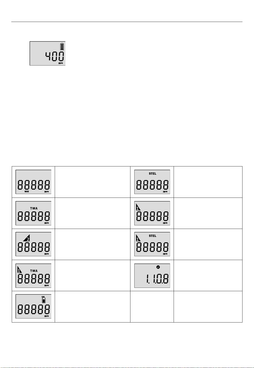
3.1. Measuring mode
When activated, gas concentration is displayed in measuring
mode
3.2. Display mode
In the measuring mode, by pressing pushbutton, the following ICONs will appear in order.
Max value -> STEL value -> TWAvalue -> 1st alarm setpoint -> 2nd alarm setpoint ->
STEL alarm setpoint -> TWA alarm setpoint ->Firmware version ->Calibration
concentration
•To move to the next menu, press the pushbutton.
•At the last step, press pushbutton or do not push any button for 10 seconds, the device
will return to the Measuring Mode.
6
Max Value Measured STEL value
Measured TWAvalue Low Alarm Value Setting
High Alarm Value Setting STELAlarm Value
Setting
TWAAlarm Value Setting Firmware version
Calibration Concentration
3. Mode

Power and Enter Button
Push Button
Power Off Booting &
Self Test
Measuring
Mode
Peak
Value
STEL
Value
TWAValue
Alarm
setpoint
STEL,TWA
setpoint
Calibration
Value
Alarm
Setting
Calibration
Peak Value
Clear
TWA, STEL
Clear
Measuring
Unit Setting
Factory
Default
Test
2 sec
Fail
Click
Click : Measuring
mode
Click : Next mode
2 sec
+
Setting
process
Cal. Setting
/Process
Value Clear
Process
Value Clear
Process
Setting
process
Setup
Testing
progress
2 sec
2 sec
2 sec
2 sec
2 sec
2 sec
2 sec
CAUTION
-Clicking the Key button ( ) during the any mode, will automatically return to the Measuring Mode.
To enter to the mode, click and hold the Key Button ( ) for 2 seconds.
7
Firmware
version
3.3. Menu Tree
3. Mode

Setting Mode Symbols
Setting Submenu LCD Action
ALr 1st Alarm
2nd Alarm 1st alarm concentration setting
2nd alarm concentration setting
CAL Fresh
N2
Co2
Fresh air Calibration
N2 Calibration
Co2 Calibration
CLr MAX - Delete maximum alarm
Concentration
CLr STEL,
TWA -Delete maximum STEL and TWA
concentration
Unit %vol / ppm Concentration unit conversion
Init - Reset
Test Self
Bts Self-test
Bump test
8
In the setting mode, users can adjust setpoints, perform calibration, and reset previous
values.
1. To enter the setting mode, press and hold the pushbutton & power button
simultaneously for three seconds. The following menu ALr → CAL → Clr MAX → Clr
STEL, TWA → Unit → Init →Test is displayed.
2. To move the next menu, press the pushbutton.
3. To enter the menu, press and hold down the power button.
4. Setting Mode

1. The detector stores the last 30 event logs. If the data is filled, the new log event
overwrites the oldest log events.
2. The data log is stored at every 1minute interval, and it stores about 64,000 data logs.
3. Data logs consisting of event log, bump, calibration are stored at 1minute interval.
4. To transfer event logs and data log to a computer, follow below steps.
- Install the recent iGas detector USB link software.
- Connect the detector with a computer via a USB-C cable.
*Refer to the more information in the PC program description part. 9
Low Alarm
•Audible Alarm: 3 beeps per seconds
•LED: 3 flashes per seconds
•Vibration: 1 vibration per second
When the gas concentration exceeds alarm set points, or will be displayed and the
device will vibrate, flash (LED), and beep. To remove alarms, move to a clean air location.
When a gas concentration is decreased below the alarm setpoints, alarm will stop.
High Alarm
•Audible Alarm: 4 beeps per seconds
•LED: 4 flashes per seconds
•Vibration: 1 vibration per second
Adjust alarm setpoints
•To enter the setting mode, press and hold the pushbutton and power button
simultaneously for two seconds.
•In the alarm setting icon, press and hold down the power button for 2 seconds.
CAUTION
-Ensure that the high alarm setpoint must be greater than low alarm setpoint.
Before the alarm adjustment, check with your safety manager or dealer authorized by SENKO.
Alarm setpoints may vary by a country or company policy. Unless specified in your company’s
safety instruction, use the preset alarm setpoints.
-Ensure Standard Factory alarm set points vary depending on countries, states, and companies.
-Before changing alarm setpoints, ensure the alarm set points follow your local guidelines.
-For the safety, users are not allowed to set the 1st alarm value to zero. When attempting to set 1st
alarm to zero, the value changes to 400ppm.
- Press the pushbutton to change the alarm setpoints.
- Press the power button to save the value and
move to the next step.
4. Setting Mode
TWA and STEL Alarm
•Audible Alarm: 4 beeps per seconds
•LED: 4 flashes per seconds
•Vibration: 1 vibration per second
4.1.1. Alarm Activation
4.1.2. Adjust alarm setpoints
4.1.3. Data Log
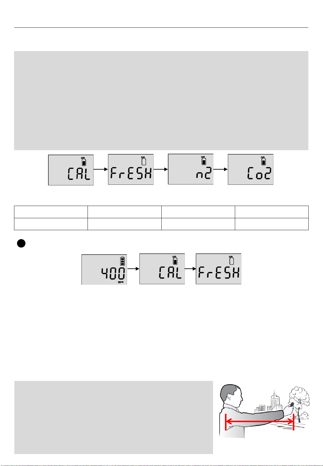
Gas Type Fresh Air (O₂) N₂CO₂
Concentration 20.9%vol 99.99%vol 20,000ppm, 2%vol
Calibration Gas
1. In the measurement display, press and hold down the pushbutton and power button to
enter the setting mode.
2. Press the pushbutton until the CAL mode is displayed.
3. In the CAL mode, press the power button for 2 seconds to enter the mode
4. In the arm’s length like the right image, hold the detector and for 2 seconds and press
the power button to perform the fresh air calibration.
5. Once the calibration is successful, the success message (V) mark is displayed. But, if
it fails, the FA message(X) mark is displayed.
6. After the successful calibration, the baseline is set to
400ppm(0.04%vol).
Fresh Air calibration
1
CAUTION
-Initial calibration is performed on all devices prior to shipment.
-The detector has fresh air calibration, N2 calibration and CO2 span calibration.
The sensor takes the last calibration, so if you have CO2 gas, we only recommend CO2 calibration.
If you don't have CO2 gas, N2 or fresh air calibration are also available for calibration.
- Check with your safety managers to ensure calibration accessibility.
-Note that Fresh air calibration should be performed out of your office in a fresh air and in the arm’s
length to avoid the CO2 interference from breathing.
-Before calibration, move to a fresh air, which is free of toxic and combustible gases.
-If calibration fails, perform re-calibration again. If the repeated calibration continues to fail, contact
authorized safety managers or distributors.
-The auto fresh air calibration can be set by the software manager.
Once activated, the fresh air calibration is activated every 3 days. (Refer to page.13)
4.2. Calibration
4. Setting Mode
CAUTION
-The presence of CO
₂
in uncontaminated ambient air is around
400ppm (0.04%) and it exceeds over 1000ppm (0.1%) in any
enclosed environments such as offices, workplaces, room, etc.
as a result of respiration, heat from electronic devices and poorly
ventilation. Therefore, to do fresh air calibration, the calibration
must be in outdoor and well away from a building and the
breathing zone. Ensure to hold the detector in the arms’ length
like the right image. 10
CAUTION
-Do not change the calibration concentration unless dealers or safety managers authorized by
SENKO give the permission to change to another calibration concentration.
-Use the regulator with a flow rate of 0.5LPM(Liters per minute) of a gas cylinder.
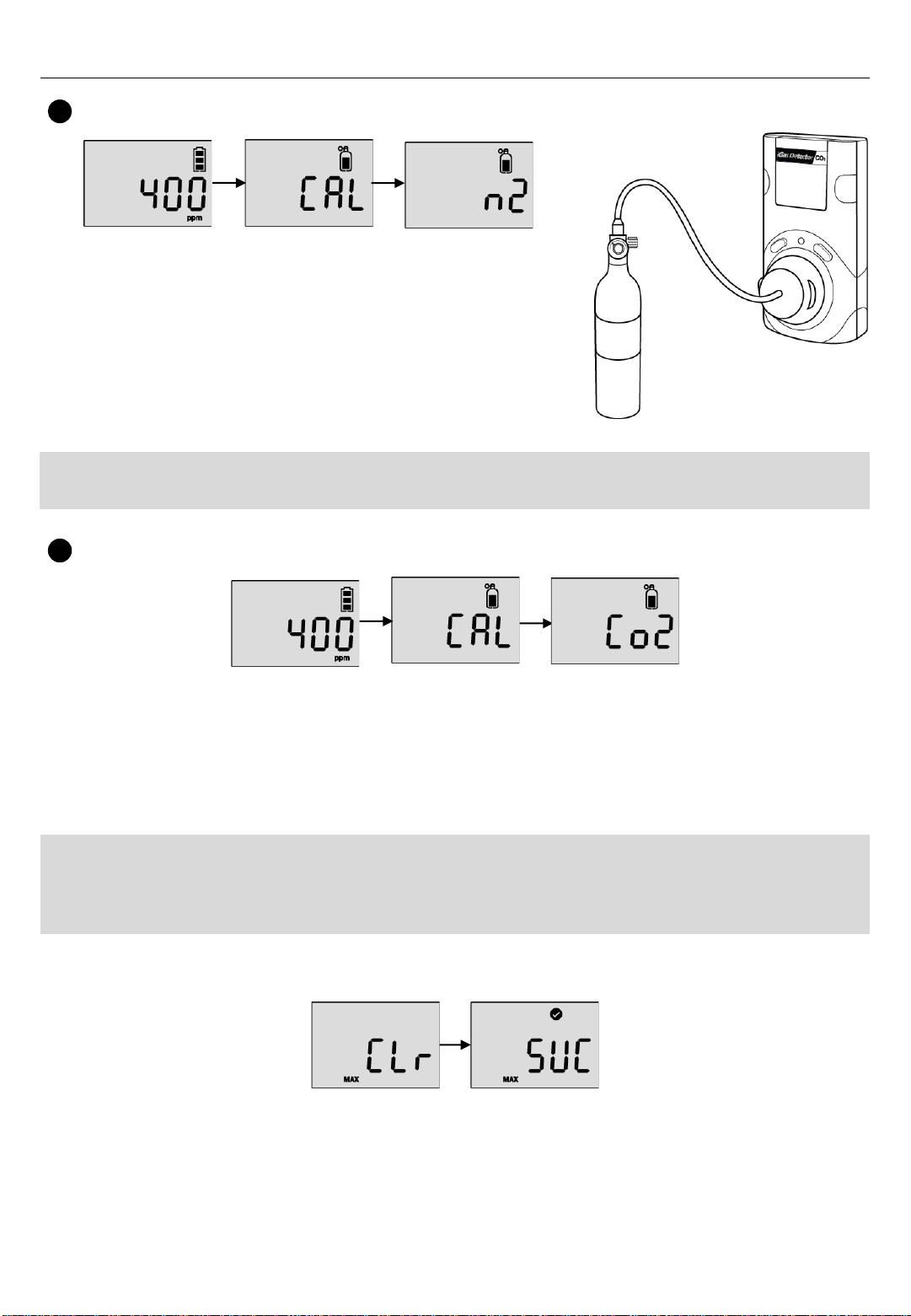
1. Press the pushbutton to move to span calibration.
2. Plug the calibration cap to the detector and connect the calibration cylinder with
CO2 (20,000ppm)
3. Press the power button and release CO2 gas.
4. After 90 seconds, when the calibration is successful, success message(V) appears.
If N2 calibration fails, fail message(X) appears.
To delete the measured peak concentration in the detector, follow below steps.
1. Press the pushbutton & power button simultaneously and the pushbutton until Clr(max)
is displayed.
2. Press the power button to clear the peak value.
3. After the successful activation, SUC (V) mark is displayed. If it fails, FA (X) mark is
displayed.
4.3. Clear max
N2 Calibration
1. In the “CAL” mode, press the pushbutton to move to
the “N2” calibration.
2. Plug the calibration cap to the detector and connect the
calibration cylinder with N2 (99.9%vol)
3. Press the power button and release the N2 gas.
4. After 90 seconds, when N2 calibration is successful,
success message(V) appears. But, If N2 calibration is
failed, FAIL message(X) appears.
2
Span Calibration
3
11
CAUTION
-Use the regulator with a flow rate of 0.5LPM(Liters per minute) of a gas cylinder.
4. Setting Mode

1. Press the pushbutton until Clr(STEL & TWA) is
displayed.
2. Press the power button to delete the TWA and STEL
value
3. After the successful activation, SUC with V mark is
displayed.
4.5. Adjust Unit
To change the unit(PPM or Vol) in the detector, follow below steps
1. Press the pushbutton until Unit is displayed and power button to enter the mode.
2. Press the pushbutton to select a unit (ppm or %vol) and power button to save it.
3. After the successful activation, SUC(V) mark is displayed. If it fails, FA(X) mark is
displayed.
4.7. Self Test
To perform the self diagnostic test, follow below steps.
1. Press the pushbutton until Test is displayed
2. Press the power button for three seconds. In the “SELF” display, press the power
button for three seconds to activate the self test. While it’s activated, the detector will
test LED, beeping, vibration, flash memory, and sensor. After the successful test, V
mark is displayed. If the test fails, FA with X mark is displayed.
3. If the self test fails, the Error message appears.
4.4. Clear STEL and TWA
4. Setting Mode
To delete the measured STEL and TWAvalue in the detector, follow below steps
4.6. Factory Reset
1. Press the pushbutton until “Initiate” is displayed.
2. Press the power button to apply it.
3. After the successful activation, SUC(V) mark is
displayed. If it fails, FA(X) mark is displayed.
To restore the factory setting, please follow below steps.
12
Note:
-When the software is opened, the fields are grayed out and before it can be used, the “OPEN”
button must be clicked.
-Without clicking the “Write” button, configured and customized settings will not be applied and
neither be saved.
-If the USB connection is successful, the “Success” icon appears. If the connection fails, reconnect
the USB cable or check the device manager to see the connection status.
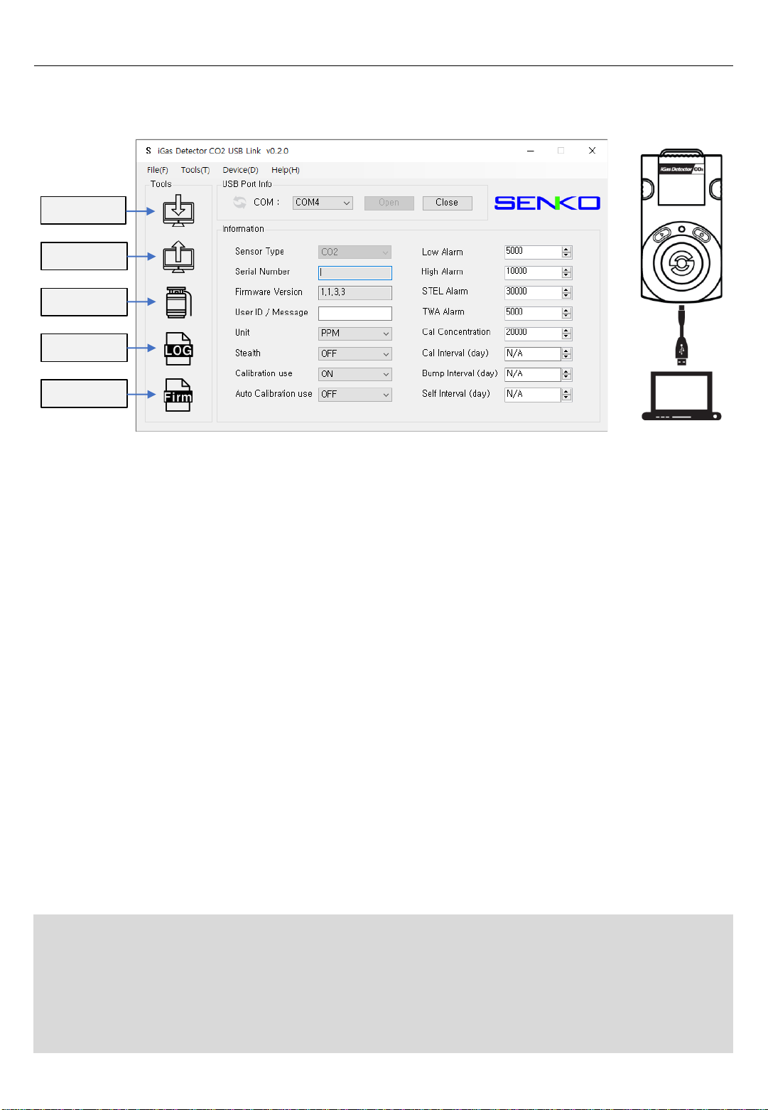
5.1. Software Overview
5. Software Manager
Read
Write
Calibration
Log
Firmware
•Sensor Type –The current sensor type in the device (CO₂, cannot be changed)
•Serial Number –iGas Detector CO2 serial number
•Firmware Version –Current firmware version of the unit (can change by upgrading)
•User ID/Message - The User ID can be used to add a usage message
•Unit –Adjust measuring unit by PPM or %vol
•Stealth –Disable the alarm, buzzer, and LED for a special occasion
•Calibration Use –Disable / Enable the calibration access for a special occasion
•Auto Calibration use – Auto “Fresh Calibration” is activated every 3 days.
•Low Alarm & High Alarm –The 1st and 2nd alarm set points (Min/Max: 400ppm
(0.04%vol) ~ 49,999ppm (5%vol)
•STEL Alarm & TWA Alarm –Short Term Exposure Limit and Time Weighted
Average level of concentration of CO₂(Min/Max: 400ppm (0.04%vol) ~ 49,999ppm
(5%vol)
•Gas Concentration –This allows a user to enter/amend correct concentration of the
gas cylinder (Min/Max: 400ppm (0.04%vol) ~ 49,999ppm (5%vol)
•Calibration Interval (day) –The calibration reminder informs every fixed day (can
adjust 0 (n/a) ~ 365)
•Bump Interval (Days) –The Bump test reminder informs every fixed day (can adjust
0 (n/a) ~ 365)
•Self Interval (Days) –The Self test reminder informs every fixed day (can adjust 0
(n/a) ~ 365) *Default is N/A
13
The “Read” button (upper-left side first icon) allows a user to retrieve the stored data.
The “Write” button (upper-left side second icon) has one of the most important role in this
software interface. Because every single and each configured or customized settings will
be saved by clicking “Write” button. When a user configures the instrument`s settings,
“Write” button will be clicked and message will pop-up. Click “Yes”.
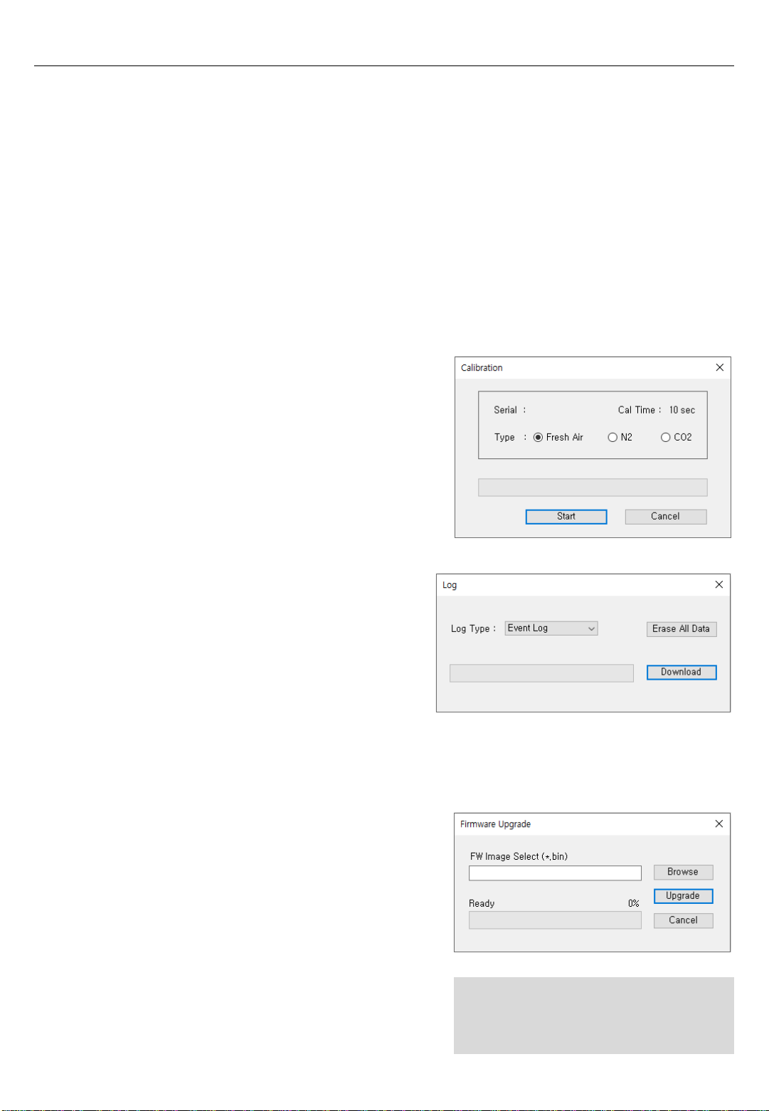
Calibration is the comparison of measurement values delivered by a device under test
with those of a calibration standard of known accuracy. To perform the calibration using
software, follow the below:
All recent 30 logs will be stored in the device and
will be automatically erases one by one from the
earliest logs when new event occurs. There are
two types of event logs, “Event Log” and “Event +
Data log” are available to download. Choose the
log and click “Download” button. The log files will
5.1.2. Write
5.1.3. Calibration
5.1.4. Log
1. Connect the unit to the PC using instrument`s
USB
2. Plug the calibration cap (not for Fresh air
calibration) and open the software
3. Click “Calibration” (middle-left side icon) and
wizard will come up
4. Choose the calibration gas type and click “Start”
5. The time for Fresh Calibration is 10seconds while
for N₂and CO₂is 90 seconds
be downloaded and created by unit`s Serial number and will be in “.csv” format. However,
clicking “Erase” button will clean all the logs from the storage of device and cannot be
recovered.
To upgrade the latest firmware version of iGas
Detector CO₂, follow the below:
1. Click “Browse” button and navigate to the
firmware location
2. Choose the firmware and click the “Open” button
3. Click “Write” to begin upgrading process
4. When upgrade is finished, power off the device
and turn it on
5. The “F-UP” → “boot” message will come up and
upgrade is complete
5.1.5. Upgrade (Firmware)
14
Note:
-Pressing “Cancel” button during the
upgrading process will cancel and
close the Firmware Upgrade Wizard.
5.1.1. Read
5. Software Manager

•Load(L) –Load the installed settings
•Save(S) –Save the current settings
•Exit(X) –Finish the work and end the
program (close the tap)
•Calibration(C) –Open the calibration
window to start calibration process
•Log Read(R) –Retrieve and save the log
events
•Log Erase(E) –Clean all the logs from the
storage (erased logs cannot be recovered)
•FW Upgrade(U) –Open the firmware
upgrade window to start upgrading process
•Self Test(S) –Automatic self diagnose of the
unit
Test order: LED → Beep → Motor → Flash
→ Sensor → End
•Factory Default(F) –Reset original settings
and specifications
•Time Write(T) –To set a time by user
location (see 8.2.3.1.)
•Power OFF(P) –Turn off the device
•IAP Version Read(I)
•Now Time – When click “Now Time”
button, automatically sets the current time
on the PC of the operator. The initial time
is preset in the factory in South Korea, so
to apply the time in your location,
press “Now time” and press “time write”.
•Time Write – By clicking “Time Write”
button, selected and customized time will
set.
5.2.1. Menu –File
5.2.2. Menu –Tools
5.2.3. Menu –Device
5.2.3.1. Menu –Device
15
5.2. Window menu
5. Software Manager
CAUTION
-Before dissembling the detector, power it off.
-It is absolutely prohibited to replace battery at potential explosion or dangerous regions.
Replace the battery in a clean environment, which has no hazardous gases.
-Replacement of components can invalidate the intrinsic safety function. Replacing the
sensor and battery should be performed by authorized sellers, agents, distributors, or safety
managers.
-The sensors published by SENKO should be used for replacement.
Product: Rechargeable Li-ion(polymer) power supply unit (500mAh)
-Service task is limited to only for sensors & battery replacement. After the sensor replacement,
recommend to perform the standard calibration with CO2.
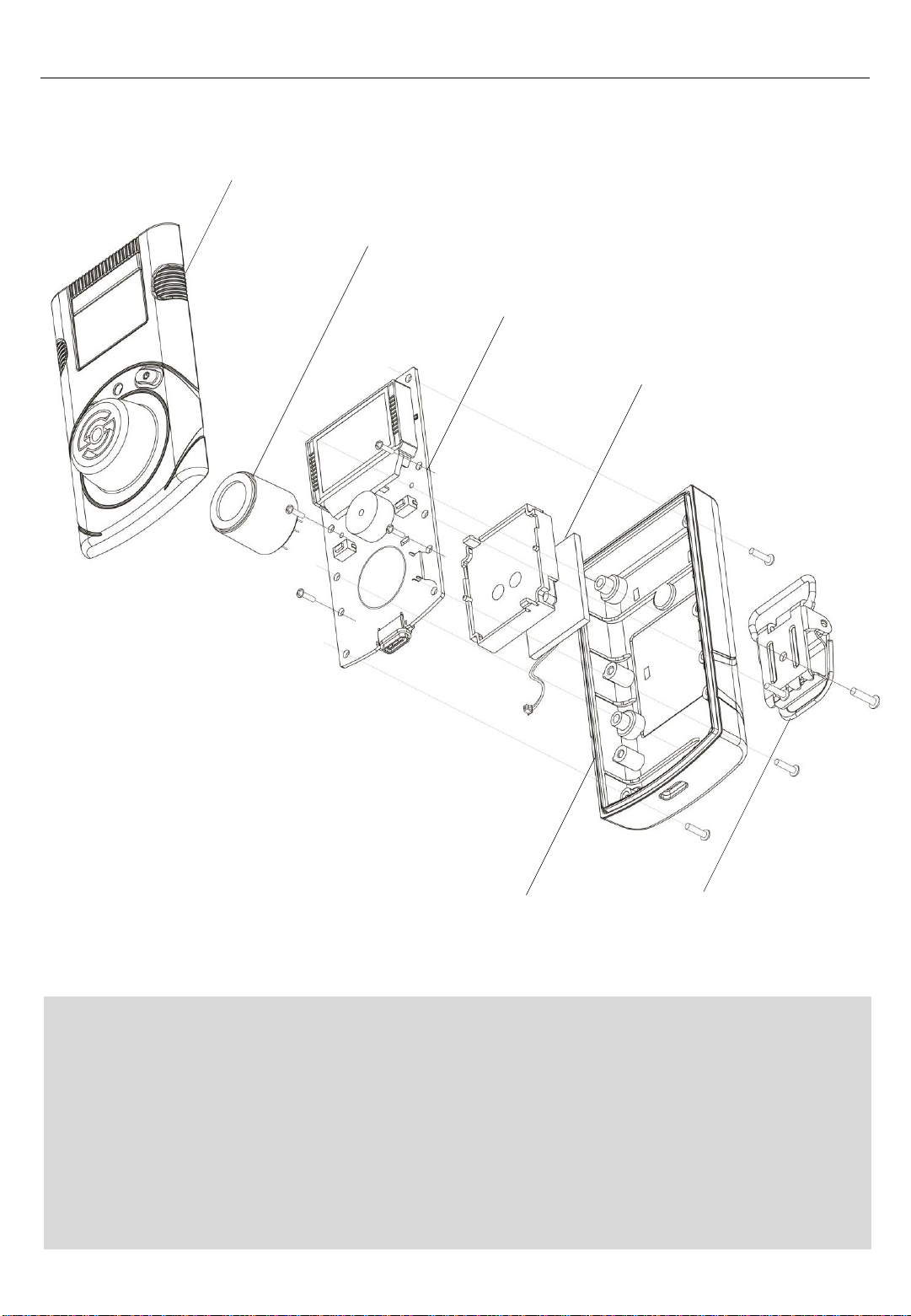
Front cover
Rear cover
PCB
Battery
Belt clip
Sensor
6. Maintenance
16

1. Move to a fresh air environment and power off the detector.
2. Remove the back case by unscrewing the 6 screws.
3. Remove the 2 screws on the PCB Board.
4. Carefully replace with the new sensor provided by the authorized dealers or SENKO.
Ensure the sensor pins are matched with the above image and the sensor is aligned
with the PCB board.
5. Assemble the detector and turn on the detector.
6. After assembling, perform the fresh air calibration, N2(99.9%vol) calibration, and
standard calibration with CO2 (2%vol) Before use, stabilize the detector for 5 minutes.
6.1. Sensor Replacement
6.2. Battery Replacement
1. Move to a fresh air environment and power off the detector.
2. Remove the back case by unscrewing the 6 screws.
3. Remove the 2 screws on the PCB Board.
4. Carefully unplug the battery from the PCB board.
5. Place the new battery in the battery protection case.
Battery Specification: Rechargeable Li-ion(polymer) power supply unit (500mAh)
6. Assemble the detector and turn on the detector.
7. Before use, stabilize the detector for 5 minutes.
6. Maintenance
CAUTION
-The sensor is soldered on the board. Before
removing the sensor, desolder the sensor pins
from the PCB board.
17

Model iGas Detector CO2
Sensor Type IR
Measurement Diffusion type
Display LCD display
Audible 90dB at 10cm
Warning Lamp Red Flashing LEDs
Vibration VibrationAlarm
Battery Rechargeable Li-ion(polymer) power supply unit (500
mAh)
Charging Time 100 minutes from empty battery to fully charge based
on
power off state and charging with adaptor
Temperature -20ºC ~ +50ºC
Humidity 5%~95%RH (Non-condensing)
Case Rubber Enclosure
Accessories Calibration Cap, Charge Cable(USB C-Type) and adaptor
Calibration Flow Rate Flow rate: 400cc (N2, CO2)
Size &Weight Size: 54(W) x 99.5(H) x 38.8(D)mm, Weight: 120g
Operating Life 14 days(Expected) (in measuring mode without alarm)
Event Log Recent 30 alarms
Approval EMC directive(2014/30/EU)
Gas Measuring range Low Alarm High Alarm Resolution
CO2 0~5.0%vol
0~50000ppm 0.5%vol
5000ppm 1%vol
10000ppm 0.001%vol
10ppm
Sensor Specification
7. Specification
8. Battery Charging
To charge the battery,
- Connect the USB-C type cable with the charging port at
bottom of the device.
- Connect the USB port with a provided adaptor (5V, 1.2A)
- While charging, the backlight illuminates.
- After the full charging, the back light turns off with full
battery symbol.
- In the low battery, the alarm is activated every three
minutes.
Note:
-The device can still charge by connecting to a PC and the
purpose of connection is not for charging but for linking the PC
program.
18

iGasDetector CO2 User’s Manual
© Copyright 2004 by SENKO CO., LTD All Right Reserved.
TechnicalSupport
If you need more information or require technical support, please contact Sales team.
Telephone +82-31-492-0445
Fax +82-31-492-0446
E-Mail: [email protected]
Senko Co., Ltd.
73, Oesammi-ro 15beon-gil, Osan-si,
Gyeonggi-do, 18111, South Korea
SENKO warrants this product to be free of defects in workmanship and materials-under
normal use and service for two years from the date of purchase from the manufacturer or
from the product’s authorized reseller.
The manufacturer is not liable (under this warranty) if its testing and examination disclose
that the alleged defect in the product does not exist or was caused by the purchaser’s (or
any third party’s) misuse, neglect, or improper installation, testing, or calibrations. Any
unauthorized attempt to repair or modify the product, or any other cause of damage
beyond the range of the intended use, including damage by fire, lightening, water damage
or other hazard, voids liability of the manufacturer.
In the event that a product should fail to perform up to manufacturer specifications during
the applicable warranty period, please contact the product’s authorized reseller or SENKO
service center at 82-31-492-0445 to repair/return information.
Limited Warranty
19
Table of contents
Other SENKO Gas Detector manuals


Popular Gas Detector manuals by other brands


Lumidor
Lumidor UniMAX-II Operator's manual

Macurco
Macurco CM-E1 User instructions

Trotec
Trotec BG40 operating manual

Perry Electric
Perry Electric 1GA 51917MET/P Installation and operating instructions

Charmeg
Charmeg SafeGas DTL26 Installation and use instruction

RKI Instruments
RKI Instruments GP-204 instruction manual