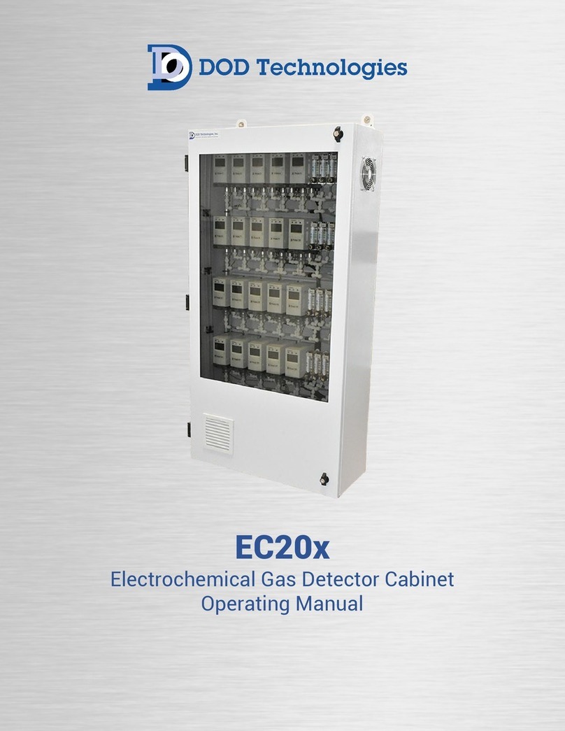
DOD Technologies EC20 Series User manual

EC20x
Electrochemical Gas Detector Cabinet
Operating Manual

3
DC-TEC-MAN-EC20x_A DODtec.com
REV 9/20/2023 815-788-5200
EC20x Cabinet Operating Manual
Chapter 1 – Overview
1.1 Introduction
DOD Technologies’ EC20x Gas Detector Cabinet is designed to house a series of single-point electrochemical
gas detectors – see specifications for compatibility. While creating a centralized hub, the EC20x is fully
customizable from the factory. This transforms a seemingly ordinary cabinet into a robust toxic gas
monitoring system (TGMS) with improved transport time and extractive detection from distances up to 600
feet.
1.2 Theory of Operation
The EC20x simply requires AC power (110VAC or 230VAC – pump dependent), sample tubing - 1/4” OD x 3/16”
ID FEP Teflon (up to 20 points) and exhaust tubing – 3/8” OD x ¼” ID x 25’ maximum (two required and
provided with your system).
The cabinet comes standard with (4) pumps total (one for points 1-10, one for points 11-20, and one backup
pump for each in case of a pump failure). If the instrument detects a pump failure, the backup pump switches
automatically and notifies the user of the problem via a Form C (NO, NC, COM) output relay (one output relay
for each primary pump). The EC20x also has a redundant power supply in case of failure and (2) Form C relays
to notify the user in the event of a failure.
WARNING : If the system is used in a manner not specified by the manufacturer, the
protection provided by the equipment may be impaired.

10
DC-TEC-MAN-EC20x_A DODtec.com
REV 9/20/2023 815-788-5200
EC20x Cabinet Operating Manual
Chapter 3 – Maintenance Alarms
Maintenance alarms are intended for the user to indicate a pump or power supply has failed. However, the
system will continue to operate utilizing the redundant/backup unit. While the system will continue to operate,
maintenance is recommended as soon as possible to maintain operation with a backup unit in place.
3.1 Vacuum Pumps with Form C Relays
The EC20x utilizes primary and redundant vacuum pumps with Form C Relays:
•Pump 1 primary for points 1-10
•Pump 2 redundant for points 1-10
•Pump 3 primary for points 11-20
•Pump 4 redundant for points 11-20
Figure 3.1 – EC20x control DIN rail view
Figure 3.1.1 – View of Form C Relays for maintenance alarms

11
DC-TEC-MAN-EC20x_A DODtec.com
REV 9/20/2023 815-788-5200
EC20x Cabinet Operating Manual
3.2 Normal Operation of Form C Relays for Maintenance Alarms
3.2.1 Vacuum Pump PUMP1FAIL Form C Relay
The Form C relay LED indicator is OFF under normal operation. Meaning the main vacuum pump is
running the system. The relay is under the NC (normally closed contact position). Also note the Latching
relay PUMP 1 RED LED is ON.
Figure 3.2.1
If the system is running with the Redundant/Backup pump the Form C relay LED indicator is ON under the
maintenance alarm condition. Meaning the Redundant/Backup pump is running the system. The relay is under
the NO (normally open contact position). Also note the Latching relay PUMP 1 RED LED is OFF.
Figure 3.2.1.1

12
DC-TEC-MAN-EC20x_A DODtec.com
REV 9/20/2023 815-788-5200
EC20x Cabinet Operating Manual
3.2.2 Vacuum Pump PUMP3FAIL Form C Relay
The Form C Relay LED indicator is OFF under normal operation. This indicates the primary vacuum pump is
running the system. The relay is under the NC (normally closed contact position). Also note the Latching relay
PUMP 3 RED LED is ON.
Figure 3.2.2
If the system is running with the Redundant/Backup pump the Form C Relay LED indicator is ON under the
maintenance alarm condition. This indicates the Redundant/Backup pump is running the system. The relay is
under the NO (normally open contact position). Also note the Latching relay PUMP 1 RED LED is OFF.
Figure 3.2.2.1

13
DC-TEC-MAN-EC20x_A DODtec.com
REV 9/20/2023 815-788-5200
EC20x Cabinet Operating Manual
3.2.3 Power Supply Maintenance Alarm P/S 1 FAIL
The Form C Relay LED indicator is ON under normal operation. This indicates the main power supply is
running the system. The relay is under the NO (normally open contact position). Also note the redundancy
module LED1 and P/S 1 DC OK green LEDs are ON.
Figure 3.2.3
If the system is running with the Redundant/Backup pump the Form C Relay LED indicator is OFF under
the maintenance alarm condition. This indicates the main power supply is running the system. The relay is
under the NC (normally closed contact position). Also note the redundancy module LED1 and P/S 1 DC OK
green LEDs are OFF.
Figure 3.2.3.1

14
DC-TEC-MAN-EC20x_A DODtec.com
REV 9/20/2023 815-788-5200
EC20x Cabinet Operating Manual
3.2.4 Power Supply Maintenance Alarm P/S 2 FAIL
The Form C Relay LED indicator is ON under normal operation. This indicates the main power supply is
running the system. The relay is under the NO (normally open contact position). Also note the redundancy
module LED2 and P/S 2 DC OK green LEDs are ON.
Figure 3.2.4
If the system is running with the Redundant/Backup pump the Form C relay LED indicator is OFF under the
maintenance alarm condition. Meaning the main power supply is running the system. The relay is under
the NC (normally closed contact position). Also note the redundancy module LED2 and P/S 2 DC OK green
LEDs are OFF.
Figure 3.2.4.1

15
DC-TEC-MAN-EC20x_A DODtec.com
REV 9/20/2023 815-788-5200
EC20x Cabinet Operating Manual
3.3 4-20mA EC20x Centralized Option (2-910-003)
When this option is installed, each extractive gas detector unit has the 4-20mA pre-wired to terminal
blocks. Those pre-wired to terminal blocks are numbered according to the point.
Figure 3.3

16
DC-TEC-MAN-EC20x_A DODtec.com
REV 9/20/2023 815-788-5200
EC20x Cabinet Operating Manual
Chapter 4 – EC20x Modbus Interface Option for Cosmos PS-7-M
Optional Modbus communication protocol for New Cosmos PS-7-M units provide a remote means to
monitor the entire system. * Please contact us for info regarding other compatible gas detector units.
4.1 EC20x Modbus Interface (Option 2-910-002)
NOTE: The DIP switches are accessible when the address plate is removed. To remove the address plate, refer
to 7-1. “Operation Procedure” of the PS-7-M series gas detector’s instruction manual.

17
DC-TEC-MAN-EC20x_A DODtec.com
REV 9/20/2023 815-788-5200
EC20x Cabinet Operating Manual
4.2 DIP Switch Setup
MODE DIP SWITCH: Set Far right dip switched as follows below, Left switch off, and Right switch ON.
Set the IP address type: “DY” or “ST” Select the IP address type between “Dynamic” and “Static” by using the IP
address type switch. When “Dynamic” is selected, IP address will be automatically assigned to the detector.
The setting here is active when the “ETHERNET (Modbus TCP)” is selected with the mode change switch.
The EC-20x Cosmos PS-7-M is to be set to ST (Static IP address) and ETHERNET as shown in the images and
table above. Further details contained in the PS-7-M Communications Specifications Guide.
Example above is for point 8 (Binary 1000).
Set the address by sliding the eight address setting switches to the “1” or “0” positions. The 8-digit number is
an 8-bit binary number representing the address. The address settable range is 1 (0000 0001) to 254 (1111
1110). Further details contained in the PS-7-M Communications Specifications Guide.

20
DC-TEC-MAN-EC20x_A DODtec.com
REV 9/20/2023 815-788-5200
EC20x Cabinet Operating Manual
Chapter 5 – EC20x Modbus/TCP Operation
1. Network access for MODBUS/TCP and Remote viewing on the EC20x is provided through LAN port 2 on
the Beckhoff IPC inside the unit as shown below.
2. The default webserver IP address on port 2 is 192.168.16.215. For remote access to the IPC, download
and install Tight-VNC. (Tight-VNC install https://www.tightvnc.com/download.php).
3. Using Tight-VNC connect to the default IP address above with a password of dod675.
4. Once the remote connection is established use these steps to change the IP address.
a. Minimize or close the application.
b. Click on Start->Control Panel
c. Select ‘Network and Sharing Center’
5. Once selected, change the adapter settings by selecting the adapter labeled ‘Ethernet’
NOTE: The following section applies to EC20x software version 23.06xx and newer. Please contact
DOD Technologies for instructions pertaining to earlier software versions.
Table of contents
Other DOD Technologies Gas Detector manuals
Popular Gas Detector manuals by other brands

AGS
AGS Merlin User & installation manual

Elektrotechnik Elektronik
Elektrotechnik Elektronik GX-A1+ operating instructions

CO-Alarm
CO-Alarm CO90 operating instructions

GEV
GEV FMG 3637 FlammEx manual

RKI Instruments
RKI Instruments GX-94 Operator's manual

NORTH EAGLES
NORTH EAGLES Eagle 1 operating instructions