Magnetic MGCplus User manual

Description
Pedestrian gate mWing
MHTM™ FlowMotion®
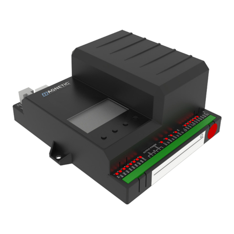
Control unit MGCplus
Doc.ID: 5817,0033EN
Version 00

2
Control unit MGCplus
MAGNETIC AUTOCONTROL GMBH
Grienmatt 20
D-79650 Schopfheim
Germany
Phone +49 7622 695 5
Fax +49 7622 695 802
www.magnetic-access.com

3
Control unit MGCplus
Contents
Contents
1 Notices on the document 7
1.1 Purpose and contents of this description 7
1.2 Symbols and illustrations used in this document 8
1.2.1 Warning notes and notes 8
1.2.2 Abbreviations used 9
1.3 Target group 10
1.3.1 Personnel – activities and qualifications 10
2 Definitions 11
2.1 General Definitions 11
2.2 Unauthorised access attempts 12
3 Operation modes 13
3.1 Description 13
3.2 Setting the Open mode via control unit 15
3.3 Special operating modes 16
3.4 Control of the passages with "Control direction 1"
and/or "Control direction 2" 17
3.4.1 Explanations 17
3.4.2 Parameter "Control variant" – Option "Variant 1" 19
3.4.3 Parameter "Control variant" – Option "Variant 2" 21
4 Digital inputs, digital outputs and relay outputs 23
4.1 Digital inputs 23
4.2 Digital outputs and relay outputs 26
5 Parameterising control unit 29
5.1 Changing menu language 29
5.2 Entering password 33
5.3 Control unit elements 34
5.4 Displays of the control unit 35
5.5 Symbols in the display 36
5.5.1 Control button functions 36
5.5.2 Further symbols 37
5.6 Setting display contrast 38

4
Control unit MGCplus
Contents
5.7 Protecting parameterisation from access 38
5.8 Parameterise value 38
5.9 Switching the "Service" mode on and off 39
6 Description of menus and parameters 40
6.1 Menu "Information" 40
6.2 Menu "Settings" 41
6.2.1 Operating mode 41
6.2.2 Validations 42
6.2.3 Speed Wings 44
6.2.4 Safety 45
6.2.4.1 General 45
6.2.4.2 Low energy 47
6.2.4.3 Intrusion 48
6.2.4.4 Wrong direction 49
6.2.4.5 Tailgating 50
6.2.5 Safety 51
6.2.5.1 Forced opening 51
6.2.5.2 Lock wings autom. 51
6.2.5.3 Warning light barriers (PE beams) 52
6.2.6 Signalling 52
6.2.6.1 Buzzer 52
6.2.6.2 GED no. 1 / GED no. 2 53
6.2.7 Random check function 56
6.2.8 Home offset 58
6.3 Menu "Inputs/Outputs" 59
6.3.1 Digital inputs 1-8 59
6.3.2 Digital outputs 1-4 and relay outputs 1-6 59
6.4 Menu "Information" 59
6.4.1 Operating mode 59
6.4.2 People Counter 59
6.4.2.1 In direction 1 59
6.4.2.2 In direction 2 60
6.4.3 Light barriers (PE beams) 60
6.5 Menu "System" 61
6.5.1 Restore settings 62
6.6 Menu "Service" 62

6
Control unit MGCplus

7
Control unit MGCplus
Notices on the document
1 Notices on the document
1.1 Purpose and contents of this description
This document describes the MGCplus control unit for the firmware versions
listed below.
The firmware number (Firmware #), the firmware name and the firmware ver-
sion (FW Version) are displayed in the "Firmware" menu (System > Control unit
> Firmware).
Firmware ID Version
49160013 (mWing) 1.0.0
Table 1: MGCplus control unit firmware version
IMPORTANT!
For information on design and function, for technical data, instal-
lation and assembly, electrical connection, commissioning and
cleaning and maintenance, see the separate operating instruc-
tions "Pedestrian gate MHTM™ FlowMotion® mWing (Doc.ID:
5817,0034)".

8
Control unit MGCplus
Notices on the document
1.2 Symbols and illustrations used in this document
1.2.1 Warning notes and notes
Warning notes are characterised by pictograms in these operating instructions.
A warning note starts with a signal word that expresses the extent of the haz-
ard.
It is absolutely essential to observe the warning notes and to proceed with cau-
tion in order to prevent accidents as well as bodily injuries and property dam-
age.
Warning Notes
DANGER
The signal word DANGER points to an immediately dangerous sit-
uation, which leads to death or severe injuries if it is not avoided.
WARNING
The signal word WARNING points to a potentially dangerous situ-
ation, which can lead to death or severe injuries if it is not avoid-
ed.
CAUTION
The signal word CAUTION points to a potentially dangerous situ-
ation, which can lead to minor injuries if it is not avoided.
NOTICE
The signal word NOTICE points to a potentially harmful situation,
which leads to property damage if it is not avoided.

9
Control unit MGCplus
Notices on the document
Notes and recommendations
IMPORTANT!
The signal word IMPORTANT highlights useful notes and recom-
mendations as well as information for an efficient and trou-
ble-free operation.
1.2.2 Abbreviations used
Abbreviation Description
Contr. Controlled
OM Open mode
D1 Direction 1 (passage direction 1)
D2 Direction 2 (passage direction 2)
React. Reaction
Val. Validated or Validation
Val. pers. Validated person
Val. pers. passed Validated person passed
Delay Delay
Table 2: Abbreviations

10
Control unit MGCplus
Notices on the document
1.3 Target group
1.3.1 Personnel – activities and qualifications
All work on the control unit may only be carried out by technicians and Mag-
netic MHTM™ FlowMotion® service experts with the following qualifications.
Designation Qualification
Technician › Has completed training as a plant mechanic, plant fitter,
assembly mechanic, assembly fitter or has a comparable
technical education.
› Has completed training as an electrical safety expert.
› Has additional knowledge and experience.
› Knows the associated technical terms and regulations.
› Can assess the work assigned to her/him, recognises
possible dangers and take suitable safety measures.
Magnetic MHTM™ FlowMotion® ser-
vice expert
› Meets all requirements of the technician.
› Trained and authorised by Magnetic.
Table 3: Qualification of the personnel – MGCplus control unit

11
Control unit MGCplus
Definitions
2 Definitions
2.1 General Definitions
B1 B2 B3 B4 B5 B6 B7 B8
B9 B10B11B12 B13B14
Master (PE receiver)
Slave (PE transmitter)
Passage direction 2
Side
1
Paid
Side
2
Unpaid
Passage direction 1
Side
2
Unpaid
Side 1
Paid
MGCplus
Master (PE receiver)
Slave (PE transmitter)
123
44
55
1
6
3
Fig. 1: Position of the light barriers (PE beams) and definitions,
shown here is C-module (see following page for descriptions)
1 Side 1, "Paid" zone
2 Passage direction 1
3 Side 2, "Unpaid" zone
4 Slave, the transmitters of the light barriers (PE beams) are installed on this side
5 Master, the receivers of the light barriers (PE beams) are installed on this side
6 Passage direction 2

12
Control unit MGCplus
Definitions
Designation Description
B1 to B14 Positioning of the light barriers (PE beams) 1 to 14.
äPage 11, Fig. 1.
Side 1 The "Side 1" corresponds to the "Paid" zone or the zone controlled
(protected area).
Side 2 The "Side 2" corresponds to the "Unpaid" zone or the zone not con-
trolled (unprotected area).
Passage
direction 1
The "Passage direction 1" corresponds to the passage direction
from the "Paid" zone to the "Unpaid" zone.
Passage
direction 2
The "Passage direction 2" corresponds to the passage direction
from the "Unpaid" zone to the "Paid" zone.
Table 4: Definitions
2.2 Unauthorised access attempts
The control unit differentiates between different kinds of unauthorised access
attempts.
Designation Description
Intrusion A person without validation enters the pedestrian gate.
Tailgating A person without validation attempts to follow a validated person.
Wrong direction An already validated person passes the pedestrian gate in direc-
tion 1, while a second person tries to enter in direction 2.
or
An already validated person passes the pedestrian gate in direc-
tion 2, while a second person tries to enter in direction 1.
Table 5: Descriptions for "Unauthorised access attempts"

13
Control unit MGCplus
Operation modes
3 Operation modes
3.1 Description
The pedestrian gate is equipped with various operating modes.
You can force the various operating modes as follows:
› Set the input with the corresponding function. For example, if you select
the "Contr. D1/Closed D2" input, this operating mode is activated. äPage
23, chapter 4.1.
› Control the behaviour of the pedestrian gate using the input functions
"Control direction 1", "Control direction 2" and "Control open mode". The
"Control variant " parameter must be parameterized to match the applica-
tion case. äPage 17, chapter 3.4 and äPage 41, "Control variant".
Input functions that force a certain operating mode have a higher priority than
the input functions "Control direction 1" and "Control direction 2".
The input function | Emergency open or emergency open have the highest pri-
ority.
Operating mode Description
No access The pedestrian gate is closed. No validations are accepted in any di-
rection. No passage is possible If a person enters the pedestrian
gate, the control unit interprets this as an unauthorised access at-
tempt.
Contr. D1/Closed
D2
Controlled direction 1 / Closed direction 2
The control unit only accepts validations in direction 1. Thus only
passages in direction 1 are possible.
In direction 2 the pedestrian gate is closed.
Closed D1/Contr.
D2
Closed D1/Controlled D2
In direction 1 the pedestrian gate is closed.
The control unit only accepts validations in direction 2. Thus only
passages in direction 2 are possible.
Contr. D1+D2 Controlled direction 1 and direction 2
The control unit accepts validations in both directions.
The validations are processed in the order in which they are re-
ceived. For example, if a validation is processed in direction 1, a
passage in direction 2 is not allowed.
Free D1/Closed
D2
Free direction 1 / Closed direction 2
No validation is required for passages in direction 1. All persons can
freely pass through the pedestrian gate in direction 1.
In direction 2 the pedestrian gate is closed.

14
Control unit MGCplus
Operation modes
Operating mode Description
Closed D1/Free
D2
Closed direction 1 / Free direction 2
In direction 1 the pedestrian gate is closed.
No validation is required for passages in direction 2. All persons can
freely pass through the pedestrian gate in direction 2.
Contr. D1/Free
D2
Validation is required for passages in direction 1.
No validation is required for passages in direction 2.
If a person is currently passing through the pedestrian gate in direc-
tion 2, this person must have left the pedestrian gate in direction 2.
Only then can a validation in direction 1 be processed.
If several validations in direction 1 are pending, they are processed
either by a passage in direction 1 or by expiration per validation of
the hold-open time. Only then can a person pass the pedestrian
gate in direction 2.
Free D1/Contr.
D2
Free direction 1 / Controlled direction 2
See description "Contr. D1/Free D2" but in reverse.
Free D1+D2 Free direction 1 and direction 2
No validation is required for passages in both directions. Simultane-
ously, only passage in one direction is possible.
For example, if a person received the access authorisation in direc-
tion 1, a passage in direction 2 is not allowed. If a person enters the
pedestrian gate in direction 2, the control unit interprets this as an
unauthorized access attempt of the "Wrong direction" type.
OM (Open
mode)
All operating modes, except the "No access" operating mode, also
exist in the open mode variant. The addition "OM" in a designation
indicates the open mode variant.
The functionality is almost identical. The only difference is that the
wings basically remain open. The wings are only closed in the event
of an unauthorised access attempt.
Table 6: Operating modes

15
Control unit MGCplus
Operation modes
3.2 Setting the Open mode via control unit
You have the following options to set the open mode for an operating mode:
› Set the input with the corresponding function as in e.g. "Contr. D1/Closed
D2 OM".
› Additionally set the input with the function "Control open mode". The input
functions are only effective in the following cases: The function "Control di-
rection 1" is assigned to an input or the function "Control direction 2" is as-
signed to an input or the functions "Control direction 1" and "Control direc-
tion 2" are each assigned to an input.
› For "Control variant" parameters, choose the "Variant 2" option. In this vari-
ant, the control unit automatically switches to open mode if an input is per-
manently set with the function "Control direction 1" or "Control direc-
tion 2". äPage 41, "Control variant".

16
Control unit MGCplus
Operation modes
3.3 Special operating modes
Operating mode Description
Boot-up The control unit boots up, initialises all hardware components and
prepares to switch the drives on to perform homing.
Wait for homing This operating mode is only relevant if the pedestrian gate is con-
trolled via the API.
Perform homing The wings are moved slowly in the direction of side 2, then in the
direction of side 1 and then to the "Closed" position. The homing
serves to exclude a mechanical defect and to find the position
"Closed".
Critical error An unrecoverable error was detected, e.g. a defective motor drive,
I/O extension, etc. The control unit of the pedestrian gate must be
reset. If the critical error continues to appear, a service technician is
required.
Emergency mode If an input is set with the "Emergency open" function or if an input
is no longer set with the "| Emergency open" function, the control
unit switches to emergency mode. The wings are opened and then
powered down.
As soon as the input is no longer set with the "Emergency open"
function or if the input is again set with the "| Emergency open"
function, the behaviour of the control unit depends on the setting
of the "Emergency options" parameter:
› Option "Auto recovery": The control unit automatically switches
to normal mode.
› Option "None": A reset is required for the control unit to switch
to normal mode.
Parameter "Emergency options": äPage 42, "Emergency op-
tions".
Reset: äPage 69, chapter 7.4.
Table 7: Special operating modes

17
Control unit MGCplus
Operation modes
3.4 Control of the passages with "Control direction 1" and/or
"Control direction 2"
3.4.1 Explanations
You have the option to control the behaviour of the pedestrian gate using the
input functions "Control direction 1", "Control direction 2" and "Control open
mode".
In addition , the parameters "Control variant" and "Delay permanent open"
must be parameterised. äPage 41, "Control variant" And äPage 41, "De-
lay permanent open".
Input functions "Control direction 1" and "Control direction 2"
With every state change "not set to set" you add a validation in the corre-
sponding direction. If the signal is longer than the time set for the "Delay per-
manent open" parameter, the free passage in the corresponding direction is
possible.
Parameter "Control variant"
Use this parameter to select the mode for the "Control direction 1", "Control
direction 2" and "Control open mode" inputs.
› Variant 1: This variant is using the "Control direction 1", "Control direc-
tion 2" and "Control open mode" inputs. The open mode variants are se-
lected with the "Control open mode" input.
› Variant 2: This variant is using only the "Control direction 1" and "Control di-
rection 2" inputs. If one of the inputs is permanently set, the corresponding
open mode variant is automatically selected.
Parameter "Delay permanent open"
You use this parameter to specify whether and after what time the permanent
open is activated for a permanent signal at the "Control direction 1" or "Con-
trol direction 2" input. Before the set time, a status change "not set to set" trig-
gers a validation. After the set time, the control unit switches to Permanent
open.

18
Control unit MGCplus
Operation modes
Chapter 3.4.2 and 3.4.3
The chapters 3.4.2 and 3.4.3 show the resulting operating mode and the result-
ing control unit behaviour depending on the input functions "Control direc-
tion 1" and "Control direction 2". Please also note the parameter descriptions
"Control variant" and "Delay permanent open".
The following symbols and abbreviations are used in the tables:
Symbol Description
Set
Not set
–Not relevant
OM (Open
mode)
The abbreviation OM indicates the open mode variant of the oper-
ating mode. In the open mode variants, the wings always remain
open. The wings are only closed in the event of an unauthorised ac-
cess attempt.
Table 8: Symbol and abbreviation explanation

19
Control unit MGCplus
Operation modes
3.4.2 Parameter "Control variant" – Option "Variant 1"
This chapter describes the control unit behaviour if the option "Variant 1" was
selected for the "Control variant" parameter.
"Variant 1" is using the "Control direction 1", "Control direction 2" and "Control
open mode" inputs. The open mode variants are selected with the "Control
open mode" input.
› Operating mode descriptions: äPage 13, chapter 3.1.
› Open mode: äPage 18, "OM (Open mode)".
› Parameter "Control variant": äPage 41, "Control variant".
Input "Con-
trol direction
..."
Validation by
changing
from not set
to set at in-
put "Control
direction ..."
Permanent
signal at in-
put "Control
direction ..."
Resulting operating mode
Resulting control unit behaviour
121212
Invalid
– – – – This variant is available in the following cases:
› The pedestrian gate is controlled via API.
› An input with a specific operating mode is set.
The validations are performed via the inputs with
the functions "Validation direction 1" or "Valida-
tion direction 2".
Contr. D1+D2
Wait for a validation in direction 1 or direction 2.
Perform a passage in direction 1.
Perform a passage in direction 2.
Depending on the sequence of validations per-
formed, perform passages in direction 1 or in direc-
tion 2.
Free D1/Contr. D2
– – Wait for a free passage in direction 1 or for an in-
coming validation in direction 2.

20
Control unit MGCplus
Operation modes
Input "Con-
trol direction
..."
Validation by
changing
from not set
to set at in-
put "Control
direction ..."
Permanent
signal at in-
put "Control
direction ..."
Resulting operating mode
Resulting control unit behaviour
121212
Contr. D1/Free D2
– Wait for an incoming validation in direction 1 or a
free passage in direction 2.
Free D1/Contr. D2
– – Process passage in direction 2.
Before the validated passage in direction 2 can be
performed, the passage in direction 1 must be com-
pleted.
Contr. D1/Free D2
– – Process passage in direction 1.
Before the validated passage in direction 1 can be
performed, the passage in direction 2 must be com-
pleted.
Free D1+D2
– – Process free passage in direction 1 or direction 2.
Contr. D1/Closed D2
––Wait for a validation in direction 1.
––Process passage in direction 1.
Free D1/Closed D2
––Process free passages in direction 1.
Closed D1/Contr. D2
––Wait for a validation in direction 2.
––Process passage in direction 2.
Closed D1/Free D2
––Process free passages in direction 2.
Table 9: Parameter "Control variant" – Option "Variant 1"
Table of contents
Other Magnetic Control Unit manuals
Popular Control Unit manuals by other brands

i3-TECHNOLOGIES
i3-TECHNOLOGIES iMO-LEARN MDM quick start guide

Dynojet
Dynojet Power Commander III USB EX installation instructions

amazipoint
amazipoint W708 installation manual

Rockwell Automation
Rockwell Automation SILVER Technology HARRY HI 1734-WS Installation & operation manual

Haier
Haier GE WE04X27596 Part Install Instructions

ICPDAS
ICPDAS HRT-710 user manual

schmersal
schmersal SRB 201ZH operating instructions

Siemens
Siemens SIRIUS Star-Delta Combination S2 Original operating instructions

Phocos
Phocos MCU user manual

Westport
Westport OMVL DREAM XXI E MP48 installation manual

HMS
HMS Anybus CompactCom 30 Design guide

Honeywell
Honeywell VCZB Series quick start guide