http://www.huidu.cn/ 5
Chapter 2 Panel
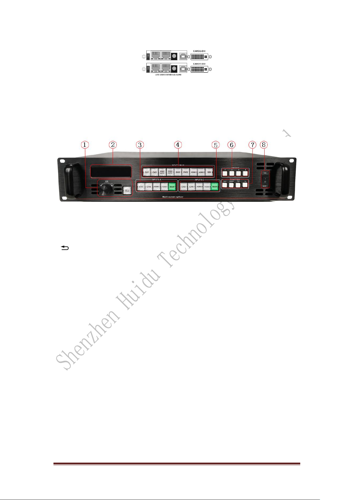
1.Rear panel
Page 1—Video processor rear panel
①AC power input —Connect to the video processor using an IEC standard power
cord with an input power of 100-240 VAC, 50-60 Hz.
②Video input —Input standard for each interface.
●CV1、CV2、
CV3、
CV4 Composite video input,With the BNC interface, the input
video supports PAL, PAL-M/N, NTSC, and SECAM formats. You can connect a
DVD player, a video camera, etc.
●DVI1, DVI2 digital video input, using DVI-I standard interface, can use DVI-I or
DVI-D cable, video input format supports VESA standard.
●HDMI1, HDMI2, HDMI3, HDMI4 HD video input, using HDMI-A standard
interface, input video supports HDMI1.3 standard and VESA standard. Commonly
used to connect desktop computers and HDMI HD players.
●VGA1, VGA2 video input, using DB-25 standard interface, input video supports
VESA standard, used to connect desktop computer, notebook or other VGA video
output device.
●SDI digital video input, SDI-LOOP, SDI signal loop out, use BNC interface, input
video supports HD camera.
③Video output —Processor programming video output interface
● DVI video output, using DVI-I connector, the output video format is set by the
processor, three groups of CH-A, CH-B, CH-C simultaneously output the same signal.
Often used to connect to an LED send card or monitor.
④CH-M/Monitor output, using DVI-I connector, output video is connected to the
display, as a display user's real-time operation image position and switching effects.
⑤RS-232 — Serial communication connector for engineering test, program burning,
PC software control, communication baud rate is 115200bps.
⑥LED Sending Card — The reserved LED sending card installation location allows
for the installation of 4 sending Cards. When installing, the user can first disassemble
the back cover and the small cover, and install and fix it. There are 6 5V power
connectors and 2.0x4 PIN connectors inside. Plug in the 5V power supply after
installation.