Huidu Technology VP1220 System manual

Spec and User Manual
2 in 1 Video processor HD-VP1220/1620
V0.1 20200930

Overview
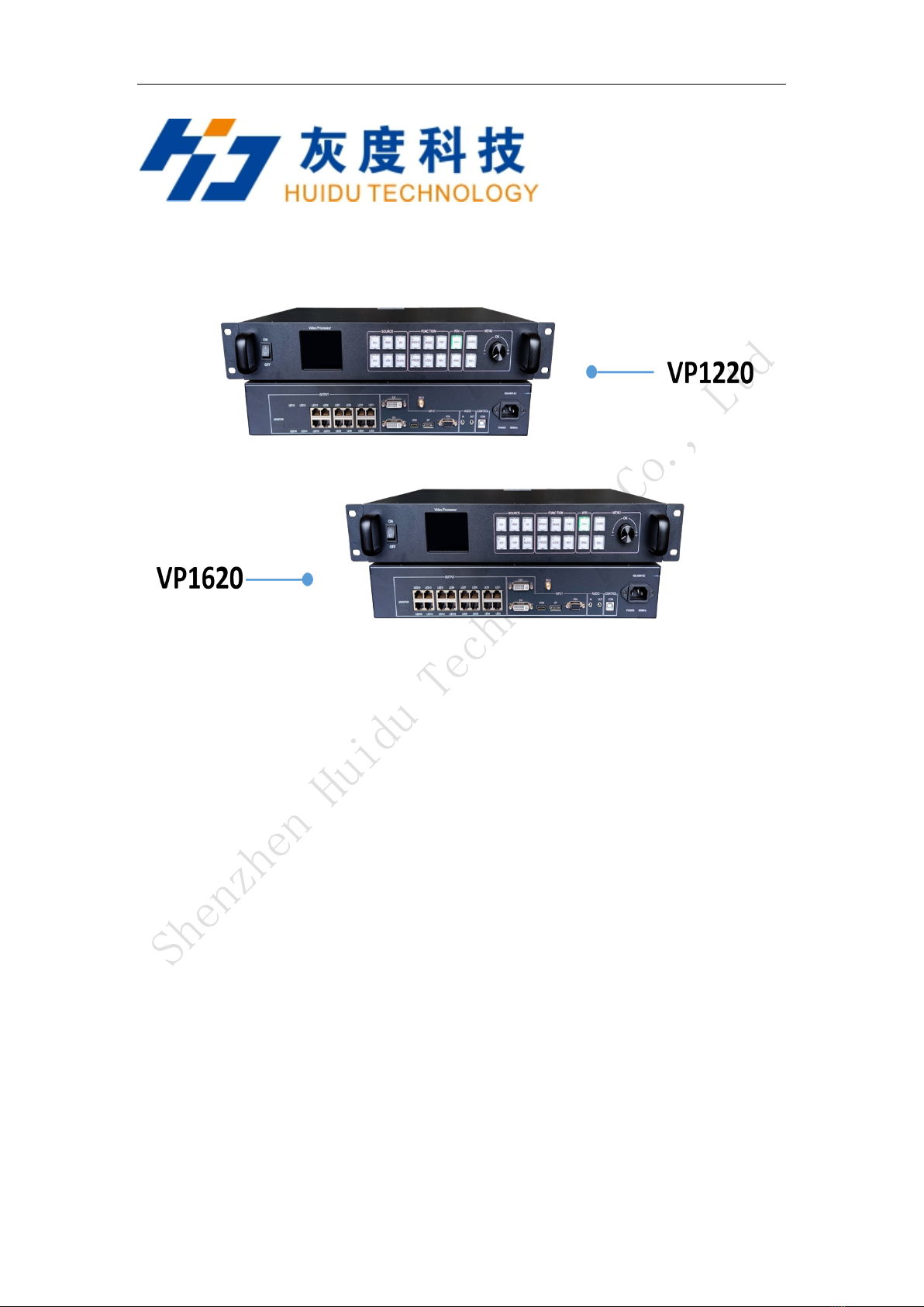
HD- VP1220 or VP1620 is one powerful 2-in-1 controller which with twelve or sixteen network
ports output, support dual live video windows integrated video processing and sending card
functions.
It product supports 4K input and is a cost-effective video processor for mid-to-high-end video
control equipment in the LED large-screen display, performance and rental, studio and other
markets.
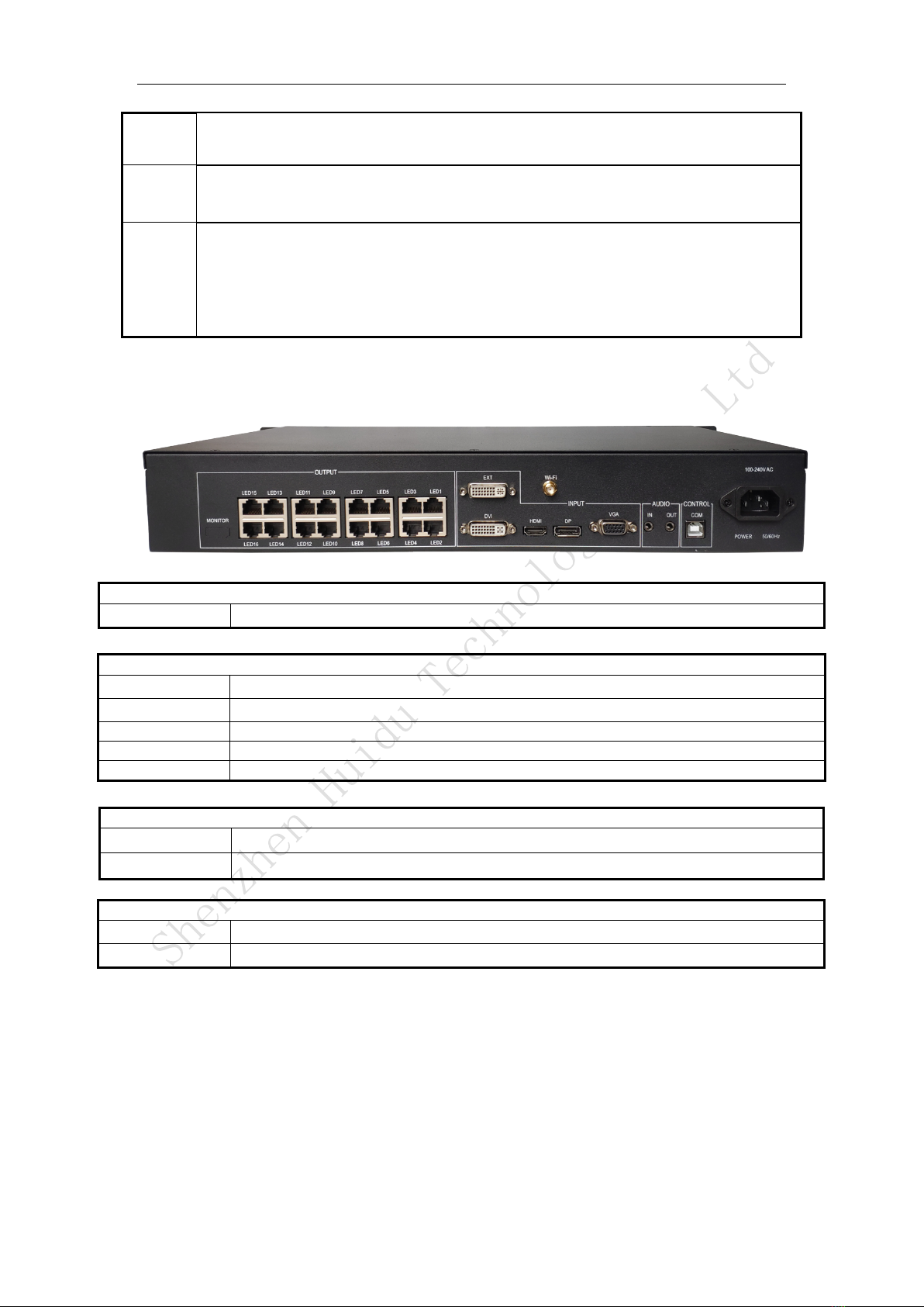
Practical video input interface —1 HD video input interface (HDMI), 1 digital video input
interface (DVI), 1 analog input interface (VGA),1 * extended EXT input interface (DVI or SDI,
factory standard DVI)。
Audio input and output —HDMI/DP audio input ,1 independent analog audio input, select 1
from 3 to send to the audio output terminal.
Debug control interface—Square USB(Type B)、Wi-Fi。
Dual-screen layout—Support dual images function,picture-in-picture PIP, picture-outside-
picture POP.
Input resolution adjustment—In DVI/HDMI/DP input mode, it supports preset and custom
adjustment of common input resolutions.
Support 68network port output—maximum load 7.8 or 10.4 million pixels, maximum width
16000, maximum 3840.
Set-and-save —The set-and-save technology solves the user's cumbersome setting and manual
storage process, the user no need to manually save after adjusting or adjusting the parameters, and
the user parameters are automatically stored in EEPROM, even if the power is turned off After the
power failure, the parameters before the power failure remain in the device.
Save template function—it can save the current settings, up to 8 groups of template parameters,
and save the parameters to the corresponding mode, which is convenient for customers to call
directly.
Key lock — lock the keys to prevent accidentally pressing the operation keys to change settings
during operation.
Application Scenario
Displaying the screen of a video playback device such as a computer/TV/camera synchronously

Connection diagram
Appearance
Front panel
Interface Description
1
Power Button
2
2.8" full-color LCD screen(320×240),display device menu information
3
SOURCE Area
Input Source Select keypad,6 buttons [DVI] ~ [DP], 5 input source port selection
buttons, corresponding to the input interface identification on the back panel.
Among them: when you press BLACK and the BALCK LED indicator is on, the output is
in a black screen state.
4
FUNCTION Area
[BRIGHT]: Quickly swap out the shortcut keys of the brightness adjustment menu.
[FREEZE]: Shortcut key for screen freeze.
[MODE]: Quickly pop up the preset mode call menu.
[LOCK]: Quickly lock the keys to prevent miss operation.

[PXP]: Quickly enter the dual picture layout menu.
[REV]: reserved function keys.
5
WIN Area
[WIN1]- [WIN2]Button: You can select the opened screen 1~2 window, and the LED
light indicates the currently selected window.
6
MENU Area
Short press the knob [OK] key: it means to enter the main menu or input confirmation.
Turn the knob clockwise to increase or the next option, counterclockwise to decrease or
the previous option.
[GUIDE] key: can quickly switch out the "smart navigation" setting interface.
Return key [ESC]: means to exit the current operation or option.
Rear Panel
Input Port
EXT
Expansion input port, the default is DVI, HDMI or SDI can be selected
DVI
DVI port
HDMI
HDMIport
DP
DP port
VGA
VGA port
Audio input and output
AUDIO_IN
Analog audio input port
AUDIO_OUT
Analog audio output port ,Selectable input source audio.
CONTROLinterface
COM
USB Control debugging interface
WIFI
WIFI Wireless control
Output Port
LED1~LED16
12/16-way network port output interface,Connect to the LED screen receiving card

Dimensions

5. Product Operation
5.1 Operation steps
Step 1: Connect the display power to the screen.
Step 2: Connect a playable input source to the HD-VP620 or VP820.
Step 3: Use the USB serial port to connect to the computer to setting screen
parameters.
5.2 Input Source Switching
HD-VP410 supports simultaneous access to 5 types of signal sources, which can be
switched to the input source to be played at any time according to requirements.
Switch input source There are two ways to switch the input source. One is to quickly
switch by pressing the “SOURCE” button on the front panel, and the other is to select
through the input source of the menu interface.
Step 1: Press the knob to select “Input Settings →Input Source” to enter the input
source interface.
Step 2: Turn the knob to select the input source.
Step 3: Press the knob to confirm that the currently selected input source is the input
of the playback screen.
Set resolution
Step 1: Press the knob to select “Input Settings →Input Resolution” to enter the input
resolution interface.
Step 2: Rotate the knob to select the desired resolution or select a custom resolution
setting.
Step 3: After setting the resolution, press the knob to determine the resolution.
5.3 Interface description

The icons in the bottom column from left to right are: brightness, sound, button lock
Main interface
Navigation interface
1. Output settings are used to set the load range and connection relationship of the sending card
network port.
2. The screen layout is used to set the output screen, and supports up to 2 screens to display at
the same time.
3. Image effects are used to set image sharpness, saturation, color temperature, brightness and
other settings.
4. Image capture is used to capture the input source of the screen. You can set the screen and
coordinates captured after the input source is entered.
5. Save mode to save current parameters forming the template file, to facilitate subsequent
quick set.
6. Advanced settings are used to set input source resolution, restore factory settings, display
firmware version, and adjust VGA.

1. Output settings are used to set the coordinates and range of the network port:
Horizontal width: 256—the width of the LED screen;
Vertical height: 128—the height of the LED screen;
Horizontal start: setting parameter range = LED screen width-horizontal width;
Vertical start: setting parameter range = LED screen height-vertical height;
2. The connection relationship is set as the connection relationship processing of the
receiving card. Currently, only standard general mode is supported, and complex
connection relationships are not supported.

The screen switch setting of screen 1 cannot be set to off
Horizontal starting value + horizontal width cannot exceed the width of the LED screen
The vertical starting value + vertical width cannot exceed the height of the LED screen
Brightness: 0-100 default 50
Sharpness: 0-10, default 5
Contrast: 0-100, default 100
Saturation: 0-100, default 50
Color temperature: warmer, natural, colder, customize. Default: Warmer

When the intercept switch is off, the knob cannot select the intercept width,
height, horizontal, and vertical start.
Intercept width: 128—Maximum width of input source
Intercept height: 64—Maximum height of input source
Horizontal start: horizontal start value range = input source width-
interception width
Vertical start: vertical start value range = input source width-interception
width.
Note: If the size of the captured screen is the same as the screen size, it will be
displayed point-to-point. If the size of the captured screen is different from the
screen size, it will be displayed by zooming.
Existing templates support replacement, deletion, and loading
non-existent template option, supports saving up to 8 template files

Supports three sets of general resolutions and supports custom resolution settings. The
default is 60Hz.

The key lock, the maximum support time is 3600 seconds, the key lock is automatically
locked after the set time, except that the key lock button functions normally, other
buttons are locked, and the function does not work.
Language selection: support English, Chinese

Firmware version
Digital function description:
When entering numbers, such as setting the width and height of the screen. The keypad is
multiplexed with related buttons. During the inputting numbers, the multiplexed buttons and ESC
are removed, and the knob can be used. Other key functions are forbidden, and they can not be
used until they are exited. The key multiplexing is as follows:
Original button function
Function after reuse
DVI
1
HDMI
2
DP
3
BRIGHT
4
MODE
5
EXT
6
VGA
7
BLACK
8
FREEZE
9
LOCK
0
Button status lights explanation
1. When the button is pressed, the button's light is on. When no other command and release the
button, the light is off.
2. If the input source of the current window is DVI/HDMI/DP/EXT/VGA, when there is no

input source signal detected, it will flash off at an interval of 125ms, and this status will last
until an input source signal is detected. If the input source signal is lost during usage , it will
continue to blink.
3. When the BLACK button, DVI, HDMI, DP, EXT, VGA lights are all off, the BLACK light is
always on, press the BLACK button again, the BLACK light is off, and then proceed to step 2
according to the input source light of the current window Light status.
4. After pressing the FREEZE button, the button light is always on, press it again to go out.
5. LOCK,LOCK state is always on, and off when unlocked.
6. REV, currently has no function and does not support light status.
7. WIN1, WIN2. Which one of the windows is currently selected by TV, then which button light
will be lit. To switch between different windows, the button light of the input source needs to
synchronize the input source type of the current window.
8. When power off and restart, the following states need to be saved: the input source type of the
current window, the state of the BLACK light, the state of FREEZE, the selection state of
win1, win2.
Enter/Exit keypad lock explanation
1. Press LOCK to lock keypad.
2. Menu newly add function of keypad lock, could be set to turn on or turn off. If turned on, the
internal timer in the MCU will lock the keypad after the set time is recorded. At the same
time, the lock button lights up.
3. When in the locked state, press the LOCK key to unlock directly. If the timer automatic lock
button function is turned on, the timer will restart to count again.
This manual suits for next models
1
Table of contents
Other Huidu Technology Media Converter manuals
Popular Media Converter manuals by other brands

Lenz
Lenz Digital plus SILVER direct Information

Expert
Expert EX-9132C-2RS485 Operation manual

HDCVT TECHNOLOGY
HDCVT TECHNOLOGY HDV-331 user manual

RDS
RDS P132 Quick installation guide

Optical Systems Design
Optical Systems Design OSD2168M Series Operator's manual

ELGO Electric
ELGO Electric AZ16I series installation manual