Humminbird HICP200 User manual

P/N: 7000717 Rev A, CO-148, Released Date: 2021-01-28; ©2021, IRRAS USA, Inc., All rights reserved
Page 1of 38
Instructions for Use
Hummingbird ICP Control Module
HICP200
Picture for Reference Only

P/N: 7000717 Rev A, CO-148, Released Date: 2021-01-28; ©2021, IRRAS USA, Inc., All rights reserved
Page 2of 38
Table of Contents
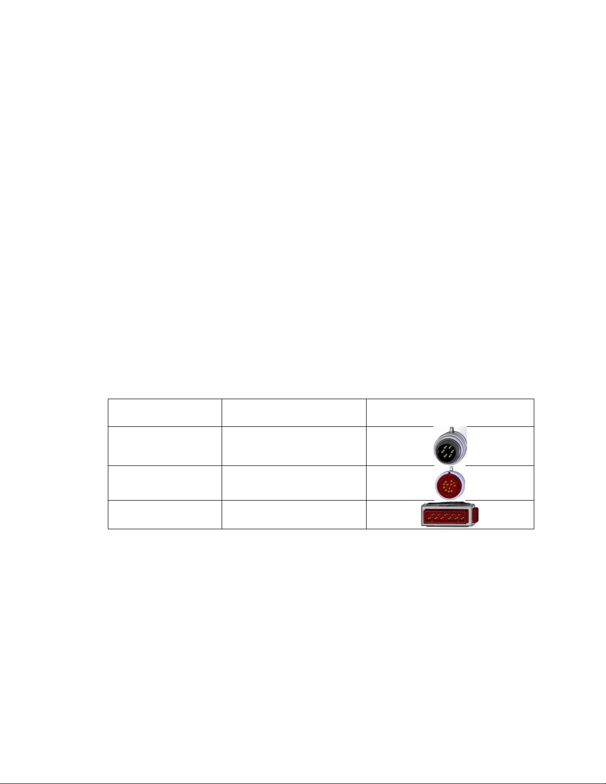
LIST OF SYMBOLS AND ABBREVIATIONS ......................................................................... 4
SYSTEM OVERVIEW............................................................................................................... 5
DESCRIPTION........................................................................................................................... 5
Indications For Use.............................................................................................................. 6
Contraindications................................................................................................................. 6
INTENDED USER....................................................................................................................... 6
COMPONENTS OF THE HUMMINGBIRD ICP CONTROL MODULE ................................... 6
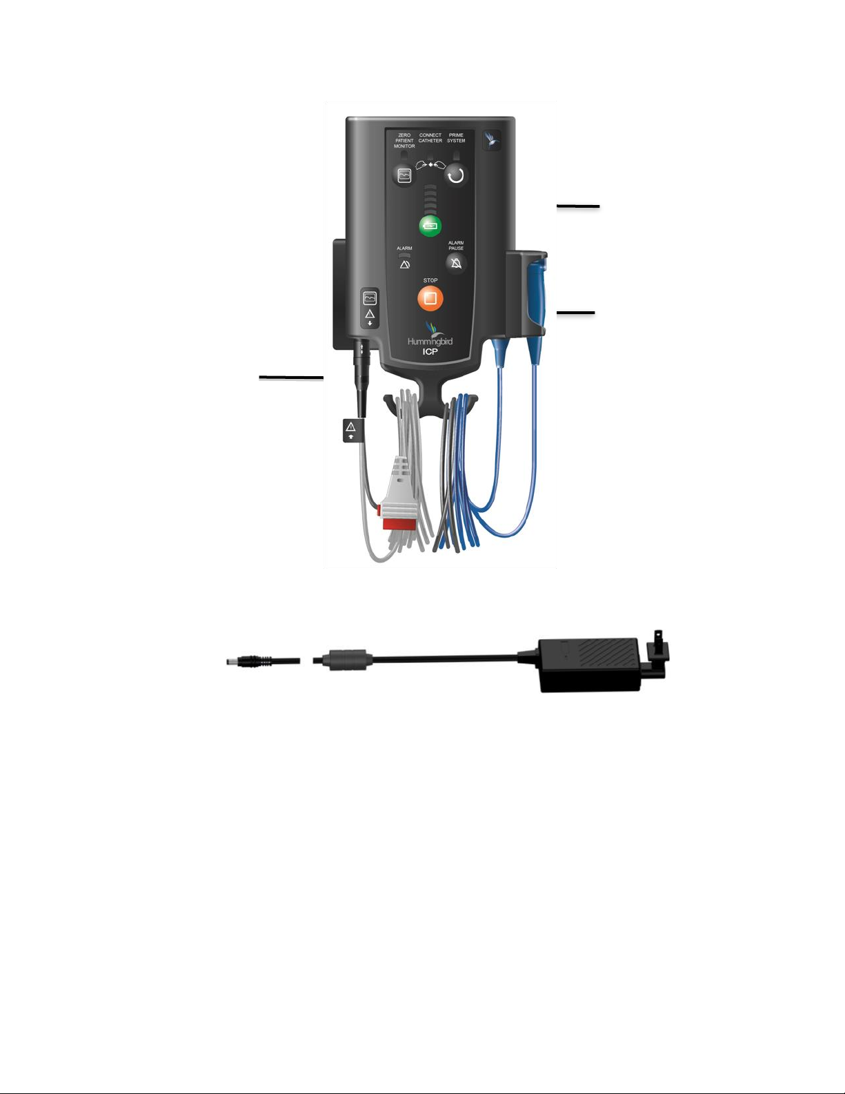
FRONT VIEW ............................................................................................................................ 7
REAR/SIDE/TOP VIEW............................................................................................................... 8
HUMMINGBIRD ICP CONTROL MODULE: SETTING UP THE SYSTEM FOR THE FIRST
TIME.......................................................................................................................................... 8
STEP 1: UNPACK THE SYSTEM (REF: HICP200)........................................................................ 8
STEP 2: ATTACH THE AC POWER SUPPLY.................................................................................. 9
STEP 3: USE AC POWER TO CHARGE THE BATTERY TO FULL CAPACITY .....................................10
STEP 4: CONNECT THE MONITOR CABLE TO THE HUMMINGBIRD ICP CONTROL MODULE .............10
SETTING UP SYSTEM FOR CLINICAL USE ........................................................................11
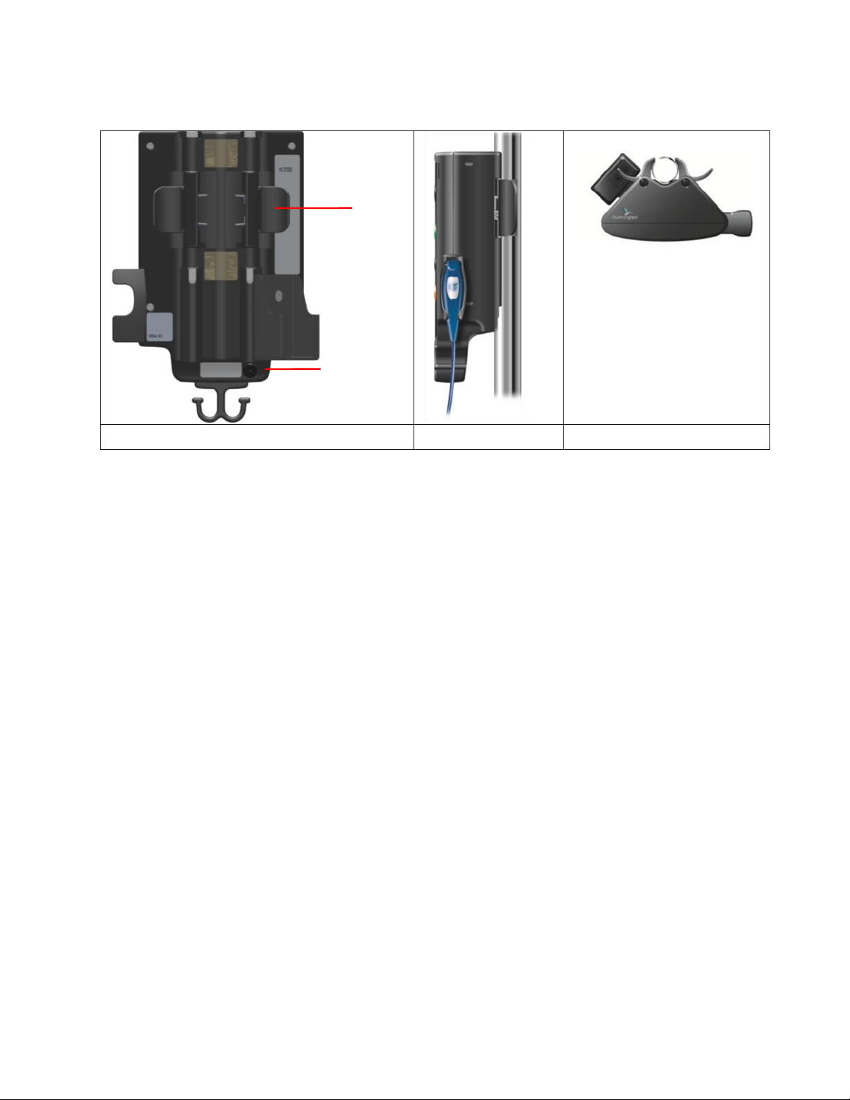
POSITIONING THE HUMMINGBIRD ICP CONTROL MODULE ..........................................................11
ATTACHING TO EQUIPMENT POLE.............................................................................................12
HUMMINGBIRD ICP CONTROL MODULE SETUP ..............................................................13
STEP 1: INSERT AND ZERO.......................................................................................................13
STEP 2: CONNECT...................................................................................................................15
STEP 3: PRIME ........................................................................................................................16
RUN MODE..............................................................................................................................17
PATIENT TRANSPORTATION......................................................................................................17
SWITCHING/SETTING UP A NEW PATIENT MONITOR.....................................................................18
SHUTDOWN /STORAGE OF THE HUMMINGBIRD ICP CONTROL MODULE ......................................18
BATTERY MANAGEMENT.....................................................................................................18
STORING THE HUMMINGBIRD ICP CONTROL MODULE..................................................19
ABOUT THE ALARMS............................................................................................................20
SILENCING AUDIO ALARMS TEMPORARILY.................................................................................21
CLEANING THE SYSTEM......................................................................................................21
CLEANING THE SYSTEM AND COMPONENTS...............................................................................21
CLEANING GUIDELINES ............................................................................................................21
CLEANING PATIENT CABLE MODULE .........................................................................................22
NOTE ABOUT HUMMINGBIRD NEUROMONITORING CATHETERS ...................................................22
TROUBLE SHOOTING THE SYSTEM...................................................................................23
TROUBLE SHOOTING ERROR CODES ........................................................................................23
CONTACTING IRRAS USA, INC. FOR TECHNICAL SUPPORT .........................................25
ABOUT TECHNICAL SUPPORT ...................................................................................................25
PRIOR TO EACH USE: ...............................................................................................................26
DURING OPERATION:...............................................................................................................26
ANNUALLY OR AFTER 6MONTHS OR LONGER IN STORAGE: .........................................................26
REPLACEMENT PARTS .............................................................................................................27

P/N: 7000717 Rev A, CO-148, Released Date: 2021-01-28; ©2021, IRRAS USA, Inc., All rights reserved
Page 3of 38
TECHNICAL SPECIFICATIONS.............................................................................................27
LIST OF TECHNICAL SPECIFICATIONS ........................................................................................27
OPERATION MODES .............................................................................................................29
CLASSIFICATION AND STANDARDS..................................................................................29
MANUFACTURER’S DECLARATION TABLE ......................................................................29
GENERAL NOTES.....................................................................................................................29
WARNINGS.....................................................................................................................34
CAUTIONS ..............................................................................................................................36
WARRANTY.............................................................................................................................37
LIMITATIONS OF LIABILITY ...................................................................................................37
RETURN GOODS POLICY ...............................................................................................37
HOW SUPPLIED .......................................................................................................................37
ORDERING INFORMATION...................................................................................................37

P/N: 7000717 Rev A, CO-148, Released Date: 2021-01-28; ©2021, IRRAS USA, Inc., All rights reserved
Page 4of 38
LIST OF SYMBOLS AND ABBREVIATIONS
Symbol
Meaning
Manufacturer
Date of manufacture expressed as year-month-day (yyyy-mm-dd).
Refer to the Instructions for Use
In the United States of America, federal law restricts this device to sale by or
on the order of a physician, physical therapist, occupational therapist, or
equivalent healthcare professional.
Monitor Interconnect Cable Port
Contents
Model number
Serial number
Type BF applied part (per IEC 60601-1)
Temperature limits
Relative humidity limits
Keep dry
Class II equipment per IEC 60601-1
Only use the Hummingbird ICP Control Module AC Power Supply with the
Hummingbird ICP Control Module device:
MR Unsafe
General Warning
CONT

P/N: 7000717 Rev A, CO-148, Released Date: 2021-01-28; ©2021, IRRAS USA, Inc., All rights reserved
Page 5of 38
SYSTEM OVERVIEW
Description
The Hummingbird ICP Control Module (REF: HICP200) is a ICP Control Module with an
integrated Patient Cable Module and a Monitor Cable specific to the hospital’s monitor. The
Hummingbird ICP Control Module, when used with a Hummingbird H110 and H610 devices
and a cable compatible with the hospital’s monitor, comprises a system whose principle of
operation is based on air-coupled pressure transduction.
The Hummingbird Patient Cable Module houses the pressure transducer and provides a
high-reliability pneumatic connection to the Hummingbird H110 and H610 devices. The
connector provides for audible and tactile feedback indicating a secure connection. The
intracranial pressure (ICP)waveform is transduced in the Patient Cable Module and the
analog signal is transmitted to the patient monitor, according to AAMI BP-22 standard
protocol of 5µV/V/mmHg.
The Hummingbird ICP Control Module monitors the same ICP signal transmitted to the
hospital monitor to control and implement system air priming cycle requirements and user
interface audio/visual system status.
The Hummingbird ICP Control Module is reusable so long as the instructions contained
herein are followed, while the Hummingbird H110 and H610 devices are single-use devices
only. The Hummingbird ICPControl Module is compatible with the following patient monitors.
Table 1: Compatible Patient Monitors and
Corresponding Monitor-Specific Cable Model Number
Patient monitor
Monitor Cable Model
Number
Image
Spacelabs Scout 6-
Pin
7000332
HP / Philips 12-Pin
Veridia
7000334
GE / Marquette Tram
11-Pin
7000335

P/N: 7000717 Rev A, CO-148, Released Date: 2021-01-28; ©2021, IRRAS USA, Inc., All rights reserved
Page 6of 38
The Hummingbird ICP Control Module only supports the following Hummingbird Devices:
Table 2:Compatible Hummingbird ICP Control Module Catheters
IRRAS Model
(REF#)
Parenchymal
ICP
Bolt
Access
Ventricular
Drainage
2-probe
ports
H110
H610
Note
Hummingbird Catheter Model #s H110 and H610 are MR Conditional at 1.5/3.0T.
The Hummingbird ICP Control Module with an integrated Patient Cable
Module and a Monitor Cable is contraindicated for use in a Magnetic
Resonance (MR) environment.
All Hummingbird devices measure ICP with a sensor that sits in the parenchyma. This design
eliminates the need for a fluid-filled system to communicate pressure (and carry waves) to
an external transducer.
Indications For Use
The Hummingbird ICP Control Module is designed for use with the Hummingbird H110 and
H610 devices. Together, they comprise a system that is indicated for use in those conditions
where continuous monitoring of ICP is required. As dictated by clinical judgment, direct
measurement of ICP may be obtained from the subdural, parenchymal, or intraventricular
locations.
Contraindications
The Hummingbird ICP Control Module with an integrated Patient Cable
Module and a Monitor Cable is contraindicated for use in a Magnetic
Resonance (MR) environment.
Intended User
The Hummingbird ICP Control Module is intended to be used by the following qualified medical
and biomedical professionals:
•A qualified healthcare professional should perform the placement and handling of the
catheters.
•Designated qualified hospital staff (e.g. neurosurgeon, nurse, intensivist, trauma
physician, or physician’s assistant) should operate the Hummingbird ICP Control
Module.
COMPONENTS OF THE HUMMINGBIRD ICP CONTROL MODULE
The following section provides information on the different components of the Hummingbird ICP
Control Module

P/N: 7000717 Rev A, CO-148, Released Date: 2021-01-28; ©2021, IRRAS USA, Inc., All rights reserved
Page 7of 38
Front View
Figure 1 –Hummingbird ICP Control Module,
Patient Cable Module, and Monitor Cable
Figure 2 –Expanded view of Front Panel showing Indicator Lights and
Control Buttons
A
C
F
J
L
K
H
Zero Patient Monitor Button
A
B
C
D
E
F
G
Connect Catheter Indicator Light
Prime System Button
Battery Status Lights/Error Codes
Pause Alarm Indicator Light
Pause Alarm Button
Zero Patient Monitor Indicator Light
DB
HBattery Status Button
I
Hummingbird, Run Mode Indicator Light
G
J
Prime System Indicator Light
E
Stop Button
K
I
Alarm Indicator Light
L
IV
II
III
MONITOR CABLE
PATIENT CABLE MODULE
AC POWER SUPPLY CABLE
I
III
II
IV
I
HUMMINGBIRD ICP CONTROL MODULE

P/N: 7000717 Rev A, CO-148, Released Date: 2021-01-28; ©2021, IRRAS USA, Inc., All rights reserved
Page 8of 38
Rear/Side/Top View
Rear View
Side View
Top View
HUMMINGBIRD ICP CONTROL MODULE: SETTING UP THE SYSTEM FOR THE
FIRST TIME
Step 1: Unpack the System (REF: HICP200)
Remove the contents from the Hummingbird ICP Control Module shipping box and
verify the following items are included.
Pole Clamp
AC Port AC Port

P/N: 7000717 Rev A, CO-148, Released Date: 2021-01-28; ©2021, IRRAS USA, Inc., All rights reserved
Page 9of 38
After unpacking the contents, inspect the shipment for any signs of damage or loss. If
any damages are discovered, notify the carrier, the supplier, and retain all shipping
cartons for examination.
Step 2: Attach the AC Power Supply
a. Remove the AC Power Supply from the package and connect the AC Power Supply
to the Hummingbird ICP Control Module.
i. Insert the plug end of the AC Power Supply into a grounded AC wall outlet.
ii. On the back of the Hummingbird ICP Control Module, attach the connector
end of the AC Power Supply into the AC Port.
ICP Control Module
Qty. 1
Patient Cable Module
Qty. 1
Monitor Cable
Qty. 1
AC Power Supply
Qty. 1

P/N: 7000717 Rev A, CO-148, Released Date: 2021-01-28; ©2021, IRRAS USA, Inc., All rights reserved
Page 10 of 38
Step 3: Use AC Power to Charge the Battery to Full Capacity
a. Keep the Hummingbird ICP Control Module on AC power for at least 10 hours.
This will charge the battery to full capacity.
b. After 10 hours, depress battery status button on the main display to verify the display
shows five green bars; this indicates the battery has full charge.
c. Use only the provided Hummingbird ICP Control Module AC Power Supply with the
Hummingbird ICP Control Module. Plug the other end of the power cord into a
hospital, 100-240 V, 50/60 Hz, wall outlet.
Step 4: Connect the Monitor Cable to the Hummingbird ICP Control Module
a. Confirm the Monitor Cable has clicked into the Hummingbird ICP Control Module
cable port and is secure.

P/N: 7000717 Rev A, CO-148, Released Date: 2021-01-28; ©2021, IRRAS USA, Inc., All rights reserved
Page 11 of 38
SETTING UP SYSTEM FOR CLINICAL USE
The following section contains instructions for positioning the monitor, powering the monitor,
and connecting catheters to the monitor.
Positioning the Hummingbird ICP Control Module
The Hummingbird ICP Control Module is
intended to be securely clamped to an
equipment pole or bed support next to the
patient. The distance between the patient and
the Hummingbird ICP Control Module (Fig. 3)
is restricted by the length of the Patient Cable
Module (6’ or 2m). The distance between the
patient monitor and the Hummingbird ICP
Control Module is restricted by the length of
the Monitor Cable (10’ or 3m).
6’ (2m)
10’ (3m)
Fig. 3 Positioning the Hummingbird ICP Control
Module Control
Module Cables

P/N: 7000717 Rev A, CO-148, Released Date: 2021-01-28; ©2021, IRRAS USA, Inc., All rights reserved
Page 12 of 38
Attaching to Equipment Pole
The Hummingbird ICP Control Module includes a clamp to attach it to an equipment
pole. To attach:
1. Position thumbs on the front panel of the ICP Control Module and the fingers
on the spring-loaded tabs (Fig. 4) on the back panel of the Hummingbird ICP
Control Module. Squeeze the tabs to open the equipment pole securement
feature.
2. Gradually release the squeeze tabs on the pole clamp (Fig. 5) to secure the
Hummingbird ICP Control Module to the equipment pole. Ensure that the
Hummingbird ICP Control Module is securely attached to the equipment pole
by pulling down slightly.
Note that the pole clamp supports equipment poles between 0.8 and 1.5 inches (20
and 38mm) in diameter.
Fig. 4 Spring loaded pole clamp
Fig. 5 Clamp attached to equipment
pole

P/N: 7000717 Rev A, CO-148, Released Date: 2021-01-28; ©2021, IRRAS USA, Inc., All rights reserved
Page 13 of 38
HUMMINGBIRD ICP CONTROL MODULE SETUP
The Hummingbird ICP Control Module Monitor Cable is designed to connect directly to the
patient monitor with Invasive Blood Pressure (IBP) measurement capability.
Turn the patient monitor on.
To operate: THINK I.C.P.
Step 1: Insert and Zero
a. Insert the Monitor Cable into the patient monitor’s IBP receptacle. A connection
from the Hummingbird ICP Control Module to the patient monitor’s IBP receptacle
will power-up the Hummingbird ICP Control Module.
b. Check functionality of the LEDs, the audible chimes, and the audible beeps. During
power-up of the Hummingbird ICP Control Module, confirm that all Hummingbird ICP
Control Module lights flash and audible indicators make a sound to ensure the alarm
indicators are functioning properly.
Note:
Connecting the Monitor Cable to the patient
monitor’s (IBP) receptacle will power-up the
Hummingbird ICP Control Module.
Note:
Indicator:
During power-up of the Hummingbird
ICP Control Modul, confirm that all lights
flash and audible indicators make a
sound. Confirm that a flat pressure
signal appears on the patient monitor.

P/N: 7000717 Rev A, CO-148, Released Date: 2021-01-28; ©2021, IRRAS USA, Inc., All rights reserved
Page 14 of 38
Note:
For ease of use, power-up the Hummingbird ICP Control Module and the patient monitor
before beginning the procedure to allow the transducer within the Patient Cable Module
to rise to an equilibrium temperature.
During setup, if repeating the LED and audible chime / beep functional check is desired,
disconnect and reconnect the Monitor Cable from the patient monitor. This action will result
in the functional check being repeated and the system going to ‘Zero Wait Mode’. If you do
not see the expected results on the Hummingbird ICP Control Module or the patient monitor,
check all connections. If you still do not see the expected results, do NOT use the
Hummingbird ICP Control Module. Contact IRRAS USA, Inc. for assistance.
c. Zero patient monitor. Use the standard hospital protocol to “Zero” the patient monitor.
Remove the catheter or HICP200 Plug (whichever is attached) on the
Hummingbird ICP Control Module Patient Cable Module prior to zeroing
patient monitor. The Patient Cable Module must communicate with
atmospheric pressure when zeroing the patient monitor. Failure to remove the
catheter and/or HICP200 Plug from the Patient Cable Module prior to re-zeroing
may result in inaccuracy.
d. Press ‘Zero Monitor’ button on the ICP Control Module.
Note:
Indicator:
The Zero patient monitor indicator light
on the main panel of the ICP Control
Module will go from flashing blue to a
solid blue.

P/N: 7000717 Rev A, CO-148, Released Date: 2021-01-28; ©2021, IRRAS USA, Inc., All rights reserved
Page 15 of 38
THINK I.C.P.
Step 2: Connect
a. Connect the Hummingbird ICP Control Module Catheter connector to the Patient
Cable Module. Push firmly, listening for an audible click.
Note:
Prior to connecting the ICP Catheter to the Patient Cable Module, the Hummingbird ICP
Control Module Catheter will have been placed. Please refer to the appropriate Hummingbird
H110 and H610 IFU for the catheter placement procedure.
Note:
Indicator:
The arrow marking on the ICP Catheter
Connector should align with the flat
(keyway) on the Patient Cable Module.
Firmly make the connection of the
catheter to the Patient Cable Module and
ensure that during the connection, there
is an audible and tactile indication of a
secure connection.
Note:
Indicator:
The Connect Catheter, Prime System
and Patient Cable Module lights will
continue to flash after the ICP Catheter
Connector and Patient Cable Module
have been connected.
Arrow
Flat

P/N: 7000717 Rev A, CO-148, Released Date: 2021-01-28; ©2021, IRRAS USA, Inc., All rights reserved
Page 16 of 38
THINK I.C.P.
Step 3: Prime
a. Press the “Prime System” button on the ICP Control Module to prime the catheter.
Note:
Indicator:
Pressing the Prime System button will
automatically prime the ICP system with
the requisite volume of air to measure
ICP.
Note:
In order to ensure that the proper volume of air is provided to the catheter’s pressure
sensing membrane, software is used to control the sequencing of events. Priming the
catheter begins with a diagnostic state to ensure that each component is operating
correctly. All event commands are routed through the System Safety Integrated Circuit
prior to implementation. This provides real-time verification of proper sequencing.
During the priming sequence, the ICP waveform on the patient monitor will be a flat line
reading approximately 0 mmHg. Do not zero the patient monitor during the priming
sequence.
Once priming is completed, the Hummingbird icon will change from a blinking blue to a
solid blue light to indicate the ICP Control Module is in the Run / Operational state.
Confirm that all 4 indicator lights across the top turn to solid blue during Run/Operational state
(Zero patient monitor, Connect Catheter, Prime System, and Hummingbird-Run Mode Icon
light)
Note:
Indicator:
The Connect Catheter, Prime
System, and Hummingbird-Run
Mode indicator lights on the main
panel of the ICP Control Module will
go from a flashing blue to a solid
blue once the priming sequence is
complete. The Hummingbird Run
Mode icon light indicates the ICP
Control Module is in the
Run/Operational state.

P/N: 7000717 Rev A, CO-148, Released Date: 2021-01-28; ©2021, IRRAS USA, Inc., All rights reserved
Page 17 of 38
Run Mode
Set appropriate intracranial pressure alarm limits on the bedside patient monitor.
Note:
For continuous monitoring of intracranial pressure intra-hospital transport, check the battery
status lights to confirm that the battery is fully charged before unplugging.
If, in Run-Mode, the catheter is disconnected and then reconnected, the Hummingbird ICP
Control Module will sense this event and require the user to re-prime the system.
The Hummingbird ICP Control Module has BLUE indicator lights for the priming operation. A
pulsating light indicates the Hummingbird ICP Control Module is being primed.
Solid BLUE lights are displayed when the Hummingbird ICP Control Module is in Run Mode.
The PRIME button can be pressed when in Run Mode to check the system and to ensure the
device is working accurately.
Note:
After the initial prime sequence, the Hummingbird ICP Control Module will automatically
perform a priming sequence three times within the first two hours: at 5 minutes, at 30
minutes and at 90 minutes and 60 minutes thereafter. This is designed to check the
integrity of the Hummingbird ICP Control Module system. During the priming sequence,
the ICP waveform on the patient monitor will be a flat line reading approximately 0 mmHg
until priming is completed (note: this shall take less than 35 seconds).
After this initial check, the Hummingbird ICP Control Module will typically re-prime
automatically every hour.
Patient Transportation
Disconnecting the Patient Cable Module from the ICP Catheter Connector to transport
the patient
1. Leave the ICP Control Module on Utility Pole and Monitor Cable attached to the IBP
port on the patient monitor.
2. Disconnect the ICP Catheter Connector from the Patient Cable Module.
3. Place the ICP Connector Cap onto ICP Catheter Connector
4. Insert the HICP200 Plug into the Patient Cable Module
5. Place the Patient Cable Module into cable hook at base of ICP Control Module.
The Hummingbird ICP Control Module with Monitor Cable and
Patient Cable Module is contraindicated for use in a Magnetic
Resonance (MR) environment.

P/N: 7000717 Rev A, CO-148, Released Date: 2021-01-28; ©2021, IRRAS USA, Inc., All rights reserved
Page 18 of 38
Note:
The Hummingbird ICP Control Module can remain on the equipment pole or be placed on the
bed for transport.
Switching/Setting up a new patient monitor
Repeat the Hummingbird ICP Control Module Setup procedure, including the
I.C.P. sequence, whenever changing the patient monitor.
Shutdown / Storage of the Hummingbird ICP Control Module
Disconnect the Monitor Cable from the patient monitor to turn off the Hummingbird ICP
Control Module.
Note:
Disconnecting the Monitor Cable will place the Hummingbird ICP Control Module in standby
state. Ensure that the ICP Control Module is plugged into an AC outlet when stored. Store
the cables with the Hummingbird ICP Control Module. If the AC Power Supply is not plugged
into the AC outlet, the battery charge will continue to deplete and the unit will alarm.
BATTERY MANAGEMENT
If the Hummingbird ICP Control Module is not used for a long duration of time, the battery will
lose charge. Always make sure the battery is charged to full capacity prior to use. The
Hummingbird ICP Control Module will charge the battery while the monitor is plugged into AC
power.
Remove Monitor Cable
from patient monitor
Disconnect ICP Connector
from the Patient Cable
Press Stop

P/N: 7000717 Rev A, CO-148, Released Date: 2021-01-28; ©2021, IRRAS USA, Inc., All rights reserved
Page 19 of 38
Routinely check the performance of the battery prior to and during use. When the AC
Power Supply is plugged into the outlet, the Battery Status Lights will be on and green.
Each light that is on indicates 20% of battery life. When the unit is operating under
battery power, the battery status lights will remain off until the Battery Status button is
pressed or the battery is less than 40% charged.
The Hummingbird ICP Control Module displays the following symbols on the status bar to
indicate battery charge levels when plugged into AC power outlet:
Symbol
Color
Available Charge
Green
80 to 100%
Green
60 to 80%
Green
40 to 60%
Green
20 to 40%
Green
Less than 20%
The Hummingbird ICP Control Module displays the following symbols on the status bar to
indicate battery charge levels when not plugged into AC power outlet:
Symbol
Color
Available Charge
Green
80 to 100%
Green
60 to 80%
Green
40 to 60%
Yellow
20 to 40%
Yellow
Less than 20%
If the level of battery charge falls to 15 minutes or less, the monitor will display an error
message on the status bar. If the level of battery charge falls to 5 minutes or less, the monitor
will activate a technical alarm.
STORING THE HUMMINGBIRD ICP CONTROL MODULE
If the Hummingbird ICP Control Module will not be used for several months or longer, keep the
monitor in a dry location that meets the following environmental conditions:
▪Temperature: 15 °C to 30 °C
▪Humidity: 20% to 80% RH, non-condensing
Also ensure the storage location is safe from any liquids that may drip inside the monitor and
damage its internal components.

P/N: 7000717 Rev A, CO-148, Released Date: 2021-01-28; ©2021, IRRAS USA, Inc., All rights reserved
Page 20 of 38
Using the Cable Hooks to Store the Monitor Cable and Patient Cable Module
The Hummingbird ICP Control Module also includes cables hooks at the base of the unit
to store the cables during storage. The cables have a Velcro strap that can be adjusted
to secure the cable loop into place.
Using the AC Power Supply Frame
The Hummingbird ICP Control Module comes with an AC Power Supply Frame that is
designed to hold the AC Power Supply during transport or storage. Loop the cable and
secure with the Velcro strap. Place the AC Power Supply into the frame.
ABOUT THE ALARMS
Physiological alarms are provided by the connected patient monitor and not the HICP200.
Technical alarms are alarms originating in the device due to faults, or scenarios that require
user intervention.
The Hummingbird ICP Control Module activates one technical alarm for exceeding the out-of-
range ICP alarm limits and several technical alarms for indicating equipment-related problems.
Fault Alarm
Level
Fault LED
Alarm Speaker
User Response
Low –Various
(See below)
Solid
On –Low priority
alarm audio
output
Press Stop button, system goes to Zero
Wait Mode
Medium -
System Fault
Blink
Yellow at
0.8 Hz
50% Duty
Cycle
On –Medium
priority alarm
output (3 beeps
that repeat)
Press Stop button, system goes to
Standby Mode
High –
Pressure Output
outside of
accurate range
Blink Red
at 2 Hz
50% Duty
Cycle
No audible alarm
output
High priority visual alarm indicates the
measured pressure is outside of the
pressure accuracy limits of the device.
Note: High priority visual alarm will be
present until measured pressure is within
the pressure accuracy range.
Table of contents
Other Humminbird Control Unit manuals
Popular Control Unit manuals by other brands

Nice
Nice FGR-223 instruction manual

FAAC
FAAC E844 3PH instruction manual

Blackrock Microsystems
Blackrock Microsystems CerePlex m Instructions for use

THE GREENBRIER COMPANIES
THE GREENBRIER COMPANIES ARI1118 Inspection and Maintenance Manual

GEM
GEM R647 Installation, operating and maintenance instructions

AUDAC
AUDAC SourceCon DMP42 user manual