manuals.online logo
Brands
  1. Home
  2. •
  3. Brands
  4. •
  5. Humminbird
  6. •
  7. Transducer
  8. •
  9. Humminbird XHS-9-20-T User manual

Humminbird XHS-9-20-T User manual

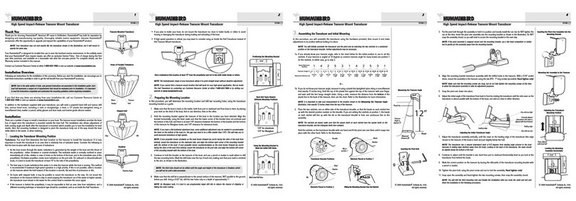
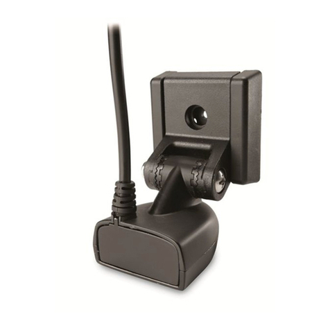
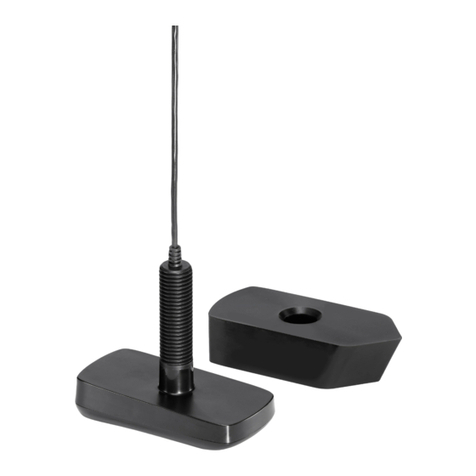
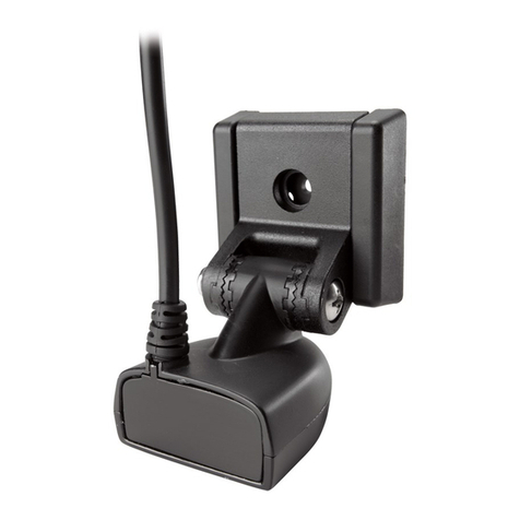
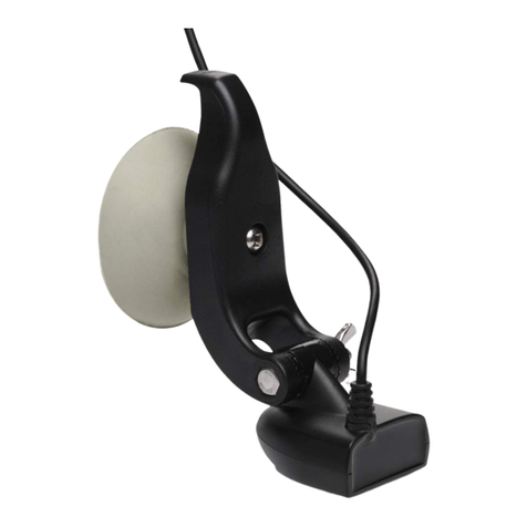
High Speed Transducer
1
Thank you for choosing Humminbird, America’s #1 name in depthsounders. Humminbird has
built its reputation by manufacturing top-quality, thoroughly reliable marine equipment. Genuine
Humminbird accessories offer the opportunity to upgrade and expand the capabilities of your
Humminbird product.
Deadrise Angle
Transom
Strakes
Hull
Rivets
Stepped Hull
THANK YOU
Transom Mounted Transducer
Figure 1
Figure 2
Figure 3
Figure 4
Step
Rib
Note: Please be aware that the transducer
design has changed. The new transducer
now uses a plastic mounting bracket and
will not fit on a metal mounting bracket. If
you are replacing or adding mounting
hardware to your current transducer, make
sure that you have selected the appropriate
hardware. If you are replacing a transducer,
you will need to replace the mounting
bracket and hardware also. For additional
information, contact the Customer
Resource Center through the Product
Support section of www.humminbird.com,
or call 334-687-0503.
Note: If you have
a High Speed Trans-
ducer with integral
temperature sensor
(-T), it is not
designed for In-hull mounting. Options
include a separate temperature sensor or
possibly an In-hull Puck Transducer with
temperature probe pigtail. Information and
guidance is available from our Customer
Resource Center at www.humminbird.com
or at 334-687-0503.
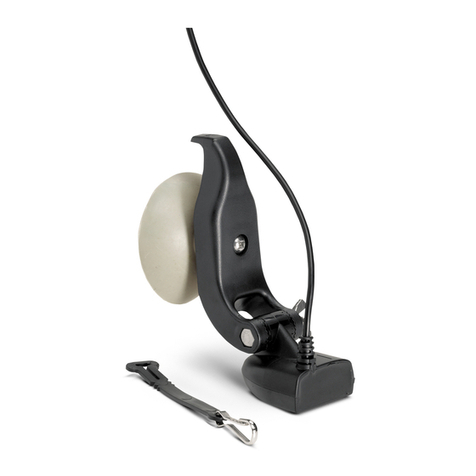
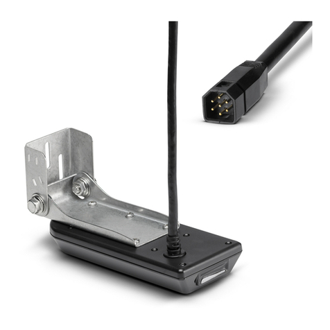
There are several ways to install a transducer on your
boat. The transom mounted installation provides the
least loss of signal, since the transducer is mounted
outside the boat hull. This installation also allows you
to adjust both running angle and depth after the
transducer is mounted, enabling you to tune the
installation for best results. The mounting hardware is
designed to pivot the transducer body out of the way
should the boat strike debris in the water, or when the
boat is out of the water. All necessary hardware is
included for this type of installation (see Figure 1).
Following are instructions
for the installation of the
High Speed Transducer.
We encourage you to read these instructions carefully
to get full benefit from your Humminbird accessory. If
you find that any items are missing from your
installation kit, contact our Customer Resource Center.
In addition to the hardware
supplied with your
transducer, you will need a
powered hand drill and various drill bits, Phillips and
flat head screwdrivers, a ruler or measuring tape, pen
or pencil, and marine-grade silicone sealant.
First, determine the best location on the transom to
install the transducer. Consider the following to find the
best location:
•It is very important to locate the transducer in an
area which is relatively free of turbulent water.
(See Figure 2) As a boat moves through the water,
turbulence is generated by the weight of the boat,
and the thrust of the propeller(s) - either
clockwise or counter-clockwise. This turbulent
water is normally confined to areas immediately
aft of ribs, strakes or rows of rivets on the bottom
of the boat, and in the immediate area of the
propeller(s) (Figure 2). Clockwise propellers create
more turbulence on the port side. On outboard or
inboard/outboard boats, it is best to locate the
transducer at least 15" (380 mm) to the side of
the propeller(s).
•The best way to locate turbulence-free water is to
view the transom while the boat is moving. This
method is recommended if maximum high-speed
operation is a high priority. If this is not possible,
select a location on the transom where the hull
forward of this location is smooth, flat and free of
protrusions or ribs.
•The hydrodynamic shape of your transducer
allows it to point straight down without deadrise
adjustment. (Figure 3)
•On boats with stepped hulls, it may be possible to
mount the transducer on the step. Do not mount
the transducer on the transom behind a step to
avoid popping the transducer out of the water at
higher speeds; the transducer must remain in the
water for the Control Head to maintain the sonar
signal. (Figure 4).
•If the transom is behind the propeller(s), it may be
impossible to find an area clear from turbulence,
and a different mounting technique or transducer
type should be considered, such as an Inside the
Hull Transducer.
1. Remove the correct
transducer mounting
template from this
sheet. Match the mounting bracket screw slots to
the template screw slots to make sure you have
selected the correct template for your transducer
mounting bracket type.
Note: Please make sure that you have
selected the correct template for your
transducer mounting bracket type, and that
you use the correct drill holes for the hull
composition of your boat.
2. Hold the template on the transom of the boat in
the location where the transducer will be installed
(Figure 15). Align the template vertically, matching
the lower edge of the transom with the bottom
corner of the template. If your propeller moves
clockwise as the boat moves forward, mount the
transducer on the starboard side, and use the
bottom left corner of the template. If your propeller
moves counter-clockwise as the boat moves
MOUNTING THE
BRACKET
LOCATING THE
TRANSDUCER
BEFORE YOU
START
ABOUT TRANSOM
MOUNT
INSTALLATION
pn530783-2 B
Attaching the Large Transducer
Assembly to the Bracket
Use Marine Grade
Silicone Sealant to
Seal Drilled Holes Use Marine Grade
Silicone Sealant to
Seal Drilled Holes
forward, mount the transducer on the port side, and use the
bottom right corner of the template.
3. Using a pencil or punch, mark the two mounting holes
(shown on the template for your type of hull) on the
transom. Do not mark or drill any other holes at this time.
1. On fiberglass hulls, it is best to
start with a smaller bit and use
progressively larger drill bits to
reduce the chance of chipping or flaking the outer coating.
Using a ⁹⁄₆₄"(3.5 mm) bit, drill the two holes to a depth of
approximately 1" (25 mm).
1. Attach the Pivot to the transducer
body, as shown in Figure 6a or
6b, depending on your
transducer type, using the #8 - ³⁄₈" (9 mm) long Phillips
headed pivot screw, nyloc nut, and the two toothed lock
washers OR the #8 - ³⁄₈" (9 mm) long Allen headed pivot
screw, headed pin, two flat washers, and the two toothed
lock washers. The toothed lock washers must be positioned
between the transducer pivot ears and the bracket pivot
tongue.
2. Using the appropriate tools, loosely tighten the pivot screw.
Do not completely tighten the assembly at this time, so that
the pivot angle can be adjusted later.
3. Insert the pivot/transducer assembly into the mounting
bracket, as shown. Do not snap the assembly closed. (See
Figures 7a and 7b.).
1. Use a marine-grade silicone
sealant to fill the drilled holes,
especially if the holes penetrated
the transom wall. (See Figures 8a and 8b.)
2. Align the transducer assembly with the drilled holes in the
transom.
3. With either a flat head screwdriver, a ⁵⁄₁₆" (8 mm) hex
driver, a ⁵⁄₁₆" (8 mm) socket, or a Phillips head screwdriver,
mount the assembly to the transom using the two #10 - 1"
(25 mm) long hex head screws or two #8 - ⁵⁄₈" Phillips
wood screws (provided). (See Figures 8a and 8b.)
4. Do not fully tighten the mounting screws at this time, to
allow vertical adjustment of the transducer. Snap the pivot
down into place.
The running position of the
transducer is now completely
adjustable. The bracket allows
height and tilt adjustment, the pivot
screws allow angular adjustment. Correct transducer height and
running angle settings are needed to ensure best performance
at all boat speeds. Initially, adjust the transducer as described
in the following paragraphs. Further adjustment may be
necessary to tweak the installation after high speed testing.
1. Cut out the correct transducer template for your transducer
type from this sheet, following the cutting directions on the
template for your type of boat hull (aluminum or fiberglass).
Adjust the height on the transom and the pivot bolt angle to
match guides on the template as shown.
2. Hand tighten the pivot bolt and mounting screws at this time.
Make sure that the height and angle have not changed.
RUNNING POSITION
ADJUSTMENT
MOUNTING THE
TRANSDUCER
ASSEMBLING THE
TRANSDUCER
DRILLING THE
MOUNTING HOLES
2
Attaching the Large (XT Series)
Transducer to the Pivot
Attaching the Small Transducer to the Pivot
Attaching the Small Transducer Assembly
to the Bracket
Small Transducer Large Transducer
Pivot
DONOTLETDEADRISE
INTERSECTTHISLINE
PLACEEITHERCORNER
ONDEADRISEANGLE
TOP
Use5/32"drill bit
Drill Drill
PLACE EITHER CORNER
ON DEADRISE ANGLE
TOP
Use 5/32" drill bit
DrillDrill
Level
Allen Wrench
Pivot
Flat Washers
Headed Pin
#8 - ³⁄₈"
Pivot
Screw
Toothed
Washer
Toothed
Washer
Angle should be 0° (level)
from port to starboard
Pivot
Transducer Pivot Assembly
Mounting Bracket
Mounting Bracket
Lock Washer
Pivot
Lock Washers
Transducer
Pivot Bolt
Nyloc Nut
Figure 5
Figure 6b
Figure 6a
Figure 7b
Figure 7a
Figure 8a
Figure 8b
Transducer
The smaller transducer
has a flat area at the back
3. Force the pivot to the Up position to gain access to
the mounting screws.
4. Make sure that the transducer location has not
changed, then fully tighten the two mounting
screws (Figure 8a or 8b). Snap the pivot back
down.
5. Confirm that the pivot angle has not changed.
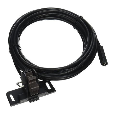
The transducer cable has
a low profile connector
that must be routed to the
point where the depthsounder will be mounted. Every
boat is different and there may be several ways to
route the cable. See Routing the Cable for instructions.
CAUTION! Do not cut or shorten the
transducer cable, and try not to damage
the cable insulation. Route the cable as far
as possible from any VHF radio antenna
cables or tachometer cables to reduce the
possibility of interference. If the cable is
too short, extension cables are available
to extend the transducer cable up to a
total of 50' (15 m). For assistance, contact
the
Customer Resource Center
at
www.humminbird.com or call 334-687-0503
for more information.
There is often a channel or conduit, used for other
wiring, on the inside of the boat, that you can use to
route the transducer cable.
1. If you choose to pass the cable through the
transom of the boat, a ⁵⁄₈" (16 mm) hole must be
drilled above the waterline. Fill this hole with
marine-grade silicone sealant, and use the
supplied escutcheon plate to dress the entry hole.
This will require two #8 x ⁵⁄₈" (16 mm) screws
provided and drilled holes of ⁹⁄₆₄" (3.5 mm). (See
Figure 9.)
2. Remember that the transducer can pivot up to 90
degrees in the bracket. Allow sufficient cable
slack for this movement. It is best to route the
cable to the side of the transducer so that the
cable will not be damaged by the transducer
during rotation. Cable clamps are provided to
secure the cable to the transom using the same
type of screws as the escutcheon plate.
1. Insert the transducer
cable into the appro-
priate terminal slot. The
cable connectors are
labeled, and there are
corresponding labels on the cable holder on the rear
of the Control Head. The slots are keyed to prevent
reversed installation, so be careful not to force the
connector into the holder.
2. Refer to your Control Head Installation Guide for
the correct procedure for installing the cable
connectors to the Humminbird Control Head.
Testing should be
performed with the boat in
the water, although you
can initially confirm basic operation while the boat is
out of the water.
1. Press POWER once to turn the Control Head on.
There will be an audible chirp when the button is
pressed correctly. If the unit does not power-up,
make sure that the collector plug is fully seated in
the receptacle and that power is available.
2.
If all connections are correct and power is available,
the Control Head will enter Normal operation.
Note: The transducer must be submerged in
water for reliable transducer detection.
3. If the bottom is visible on-screen with a digital
depth readout, the unit is working properly. Make
sure that the boat is in water greater than 2'
(.6 m) but less than the depth capability of the
unit, and that the transducer is fully submerged,
since the sonar signal cannot pass through air.
4. If the unit is working properly, gradually increase
the boat speed to test high-speed performance. If
the unit functions well at low speeds but begins to
skip or miss the bottom at higher speeds, the
transducer requires adjustment.
5. If you have the correct angle set on the transducer,
yet lose a bottom reading at high speed, adjust the
transducer to a lower depth in the water. If you
reach the top of the screw slots and continue to lack
high speed performance, increase the angle of the
transducer by lowering the back of the transducer in
increments of ¹⁄₈" (4 mm); see Figure 10.
Note: It is often necessary to make several
incremental transducer adjustments before
optimum high speed performance is achieved.
INSTALLATION
TESTING
CONNECTING THE
CABLE TO THE
CONTROL HEAD
ROUTING THE
CABLE
3
Mounting the
Transducer to the Transom
A = ¹⁄₈
" -
¹⁄₄
" (3 - 6 mm) Fiberglass Hulls
¹⁄₄
" -
¹⁄₂
" (6 - 13 mm) Aluminum Hulls
B = ¹⁄₄
" (6 mm)
AB
Figure 10
Routing the
Cable
⁵⁄₈" (16 mm) Hole
Escutcheon
Plate
Cable Clamp
Figure 9
Installing the Third Mounting Screw
Figure 11
Fiberglass
Adjusting the Running Position
High Speed Transducer
4
CUSTOMER RESOURCE CENTER
Aluminum
Fiberglass
380
Your Humminbird accessory is designed for trouble-free
operation and is backed by the same warranty as our
depthsounders, VHF marine-band radios, and GPS
navigation equipment. Refer to your Humminbird Warranty
Card for the specific details of this warranty. If you have any
questions, visit our web site at www.humminbird.com,
select the Product Support tab/link or call our Humminbird
Customer Resource Center:
WARNING:
Disassembly and repair of this electronic unit should
only be performed by authorized service personnel. Any modification
of the serial number or attempt to repair the original equipment or
accessories by unauthorized individuals will void the warranty.
Handling and/or opening this unit may result in exposure to lead, in
the form of solder.
WARNING: This product contains lead, a chemical known
to the State of California to cause cancer and birth defects
and other reproductive harm.
WARNING: Avoid contact or close proximity with the transducer during
operation of your fishfinder. Touching any transducer during operation can
cause discomfort and may lead to personal injury. Handle the transducer
only when the power of the fishfinder is off.
Important: For Transom Mount transducer installations, install
the third mounting screw after the final transducer adjustments.
Hand tighten only (see Figure 11).
Your depthsounder is now ready for operation.
Note: If your depthsounder is temperature-capable, your
transducer includes a temperature probe. When your
transducer is hooked up, the temperature probe will allow
your depthsounder to display water temperature
automatically.
This accessory works with a number of Humminbird depthsounder
products. Some products may require disassembly of the depthsounder
mounting bracket in order to connect the cable. Refer to the operation manual
for your depthsounder.
If your boat remains in the water for long periods of
time, algae and other marine growth can reduce
the effectiveness of the transducer. Periodically clean the face of the
transducer with a biodegradable detergent or hot water.
WARNING! Do not touch an active transducer during
operation, as this may cause physical discomfort and may
result in personal injury in the form of tissue damage.
Handle the transducer only when the power to the
depthsounder is off.
Pivoting the transducer up in the bracket may allow better access for
inspection or cleaning. During cleaning, your boat should not be running, and
this procedure is normally performed while the boat is out of the water.
In some cases it may take some time to wet the transducer when returned
to the water. Small air bubbles can cling to the surface of the transducer and
interfere with proper operation. These bubbles will dissipate with time, or you
may wipe the face of the transducer with your fingers after the transducer is in
the water.
MAINTENANCE
334-687-0503
Throughout the U.S. and Canada, hours are: Monday-Friday,
8:00 a.m. to 4:30 p.m. Central time
Humminbird
108 Maple Lane
Eufaula, AL 36027

Other Humminbird Transducer manuals

Humminbird MEGA 360 IMAGING Series User manual

Humminbird

Humminbird MEGA 360 IMAGING Series User manual

Humminbird ICE Flasher Series User manual

Humminbird

Humminbird ICE Flasher Series User manual

Humminbird MEGA 360 IMAGING Series User manual

Humminbird

Humminbird MEGA 360 IMAGING Series User manual

Humminbird XTH 9 20 P User manual

Humminbird

Humminbird XTH 9 20 P User manual

Humminbird Bronze Thru-Hull Transducer User manual

Humminbird

Humminbird Bronze Thru-Hull Transducer User manual

Humminbird 900 Series User manual

Humminbird

Humminbird 900 Series User manual

Humminbird APEX Series User manual

Humminbird

Humminbird APEX Series User manual

Humminbird XP 9 20 T User manual

Humminbird

Humminbird XP 9 20 T User manual

Humminbird Transducer User manual

Humminbird

Humminbird Transducer User manual

Humminbird transducer User manual

Humminbird

Humminbird transducer User manual

Humminbird XNT 9 20 User manual

Humminbird

Humminbird XNT 9 20 User manual

Humminbird XTH 9 DB 74 P User manual

Humminbird

Humminbird XTH 9 DB 74 P User manual

Humminbird 531392-2_B Installation guide

Humminbird

Humminbird 531392-2_B Installation guide

Humminbird transducer Quick reference guide

Humminbird

Humminbird transducer Quick reference guide

Humminbird MEGA Llive ICE Imaging User manual

Humminbird

Humminbird MEGA Llive ICE Imaging User manual

Humminbird 900 Series User manual

Humminbird

Humminbird 900 Series User manual

Humminbird SIDE IMAGING User manual

Humminbird

Humminbird SIDE IMAGING User manual

Humminbird MEGA Live User manual

Humminbird

Humminbird MEGA Live User manual

Humminbird XPT 9 HW T User manual

Humminbird

Humminbird XPT 9 HW T User manual

Humminbird High Speed Transducer User manual

Humminbird

Humminbird High Speed Transducer User manual

Humminbird TROLLING MOTOR TRANSDUCER User manual

Humminbird

Humminbird TROLLING MOTOR TRANSDUCER User manual

Humminbird 530511-3_A User manual

Humminbird

Humminbird 530511-3_A User manual

Humminbird ICE HELIX Series User manual

Humminbird

Humminbird ICE HELIX Series User manual

Humminbird HDR 200 User manual

Humminbird

Humminbird HDR 200 User manual

Popular Transducer manuals by other brands

Caen ELS CT-BOX quick start guide

Caen ELS

Caen ELS CT-BOX quick start guide

HYDACELECTRONIC HDA 4800 user manual

HYDACELECTRONIC

HYDACELECTRONIC HDA 4800 user manual

B-K Medical 8870 user guide

B-K Medical

B-K Medical 8870 user guide

Kongsberg Simrad 50/200 Combi D installation manual

Kongsberg

Kongsberg Simrad 50/200 Combi D installation manual

Siemens SITRANS 7ML1105 Compact operating instructions

Siemens

Siemens SITRANS 7ML1105 Compact operating instructions

BROSA 0210 operating manual

BROSA

BROSA 0210 operating manual

HBM Z30A Mounting instructions

HBM

HBM Z30A Mounting instructions

Lumel P18D user manual

Lumel

Lumel P18D user manual

Iskra MT406 user manual

Iskra

Iskra MT406 user manual

Loreme CAL4/100ig Safety manual

Loreme

Loreme CAL4/100ig Safety manual

Daiichi Electronics PTT2-92A-12 instruction manual

Daiichi Electronics

Daiichi Electronics PTT2-92A-12 instruction manual

TR-Electronic LMRI-46 1150 SSI manual

TR-Electronic

TR-Electronic LMRI-46 1150 SSI manual

K&K Sound GOLDEN TRINITY product manual

K&K Sound

K&K Sound GOLDEN TRINITY product manual

Thyracont VSR53MA4 operating instructions

Thyracont

Thyracont VSR53MA4 operating instructions

LEI Extras Skimmer installation instructions

LEI Extras

LEI Extras Skimmer installation instructions

ProMinent Dulcometer DMT operating instructions

ProMinent

ProMinent Dulcometer DMT operating instructions

Simrad ES120-7C -  REV D Dimensions

Simrad

Simrad ES120-7C - REV D Dimensions

M-system LTHZ instruction manual

M-system

M-system LTHZ instruction manual

manuals.online logo
manuals.online logoBrands
  • About & Mission
  • Contact us
  • Privacy Policy
  • Terms and Conditions

Copyright 2025 Manuals.Online. All Rights Reserved.