Hunt HKB-200 User manual

INTEGRATED CONTROLLER HKB-200
HKB-200
Please read the instructions carefully and keep this manual for future reference.
USER’S MANUAL
P/N : HKB-200
PRINTED IN KOREA
Distributed by

USE PRECAUTIONS
02 INTEGRATED CONTROLLER HKB-200
03 INTEGRATED CONTROLLER HKB-200
CONTENTS
To prevent risk or damage on the property must keep the following information please.
• Before using this product, please be sure to read the user manual.
. Install this product in the stable and right place.
. Do not place conductive material (such as screw driver, coin, iron…etc. )nor vessel full of water.
. Use the indicated power only.(DC 12V).
. Do not use this product where flammable substances are used.
. Do not touch electrical parts with wet hands.
. Products used to be a problem, please discontinue.
. When this product is not normally operated, contact seller or service center.
Never disassemble the equipment.
(Problems caused by user’s disassembly are not responsible.)
Warning: Violation of the instructions may cause death or injury.
Caution: Violation of the instructions may cause personal injury or property damage.
*Please note the "Warning" and "Caution“.
"Warning" and "Caution" mean as follows.
. USE PRECAUTIONS ………………………………………………
1.WARNING
2.CAUTION
3.MAINENENCE
. MAIN FUNCTIONS AND FEATURES…………………………………
1.Summary
2.Feature
3.Controller Button Overview
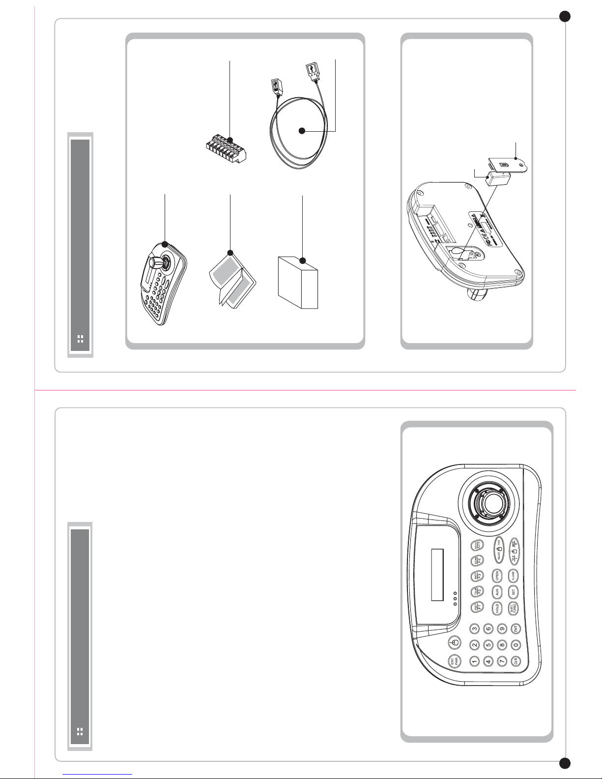
. CONTENTS AND BATTERY CHANGE ………………………………
1.Products
2.Battery Change
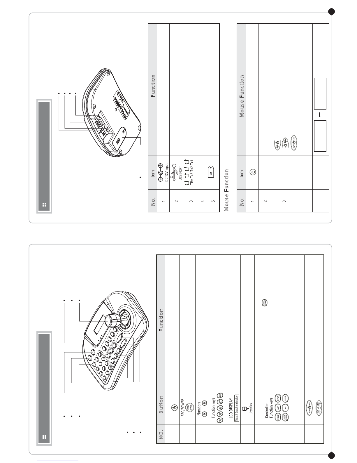
. HARDWARE OVERVIEW……………………………………………
. PART NAME & FUNCTION …………………………………………
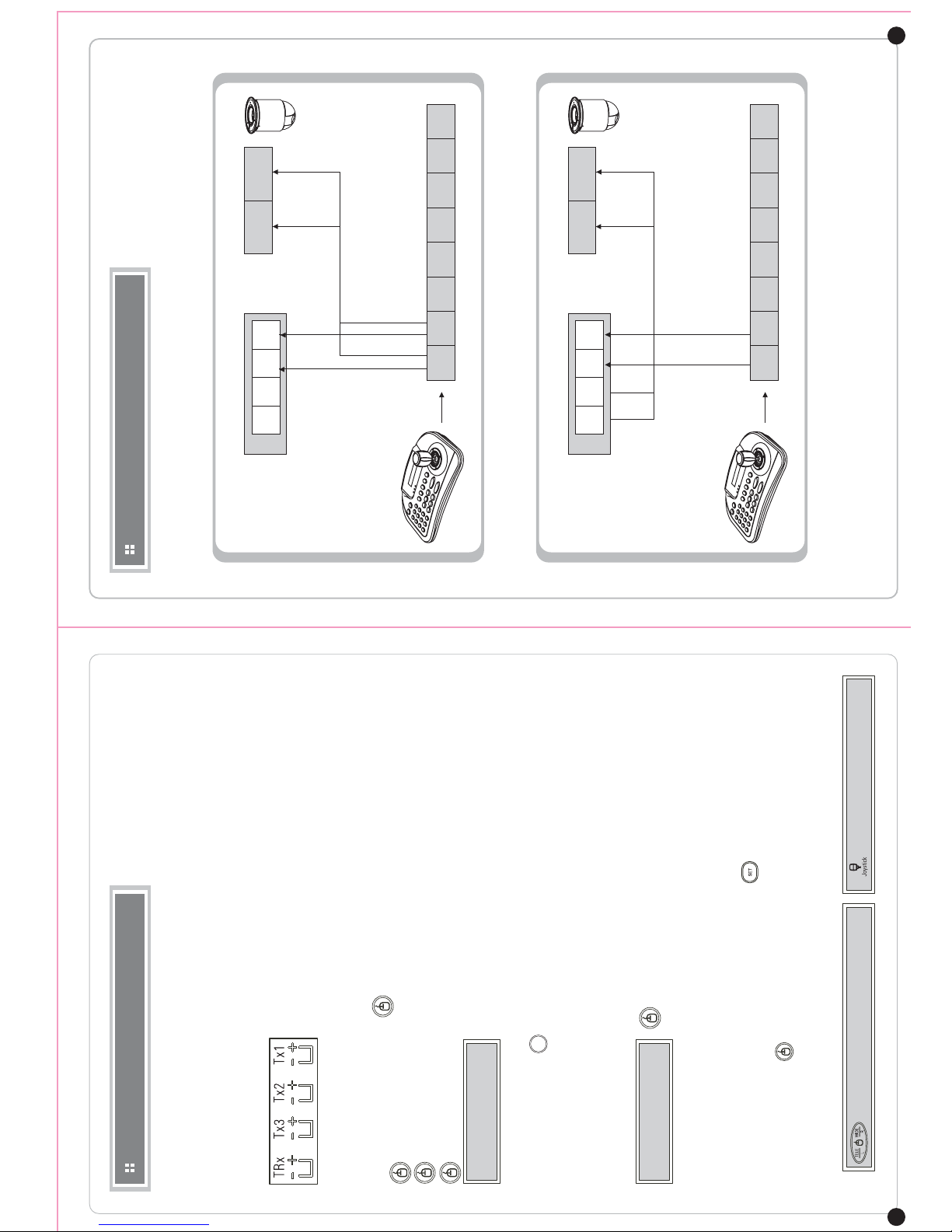
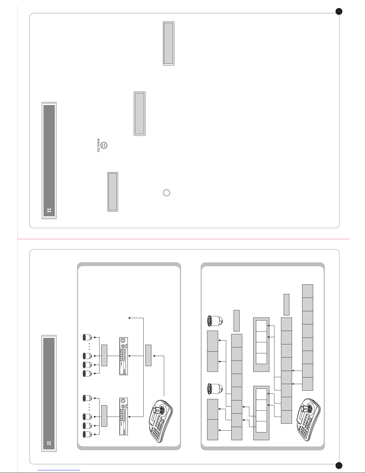
. CONNECTION ……………………………………………………
RS-485/422 connection
DVR connection
WTX-1200A and DVR mouse function use
. SYSTEM CONFIGURATION…………………………………………
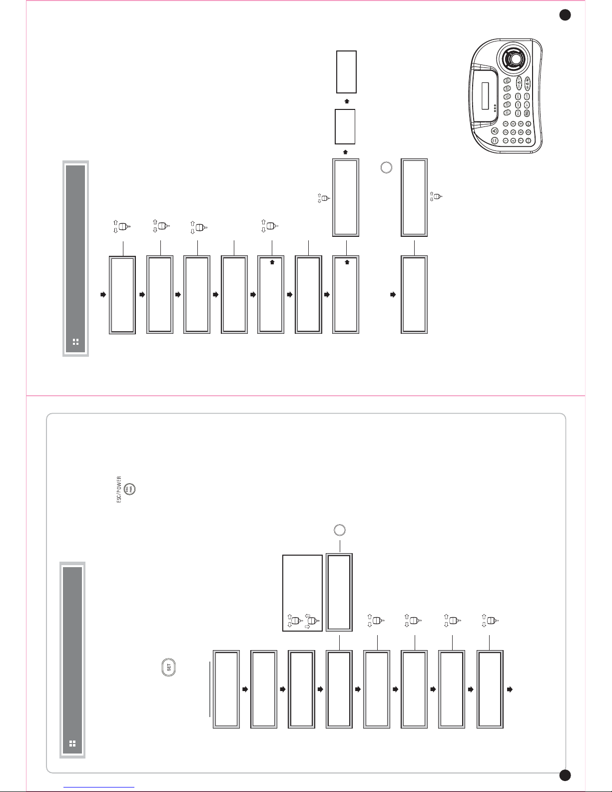
. PTZ Control …………………………………………………………
1.Power On
2.LCD display
3.Camera ID Set Up
. CONTROLLER CONTROL / SET UP …………………………………
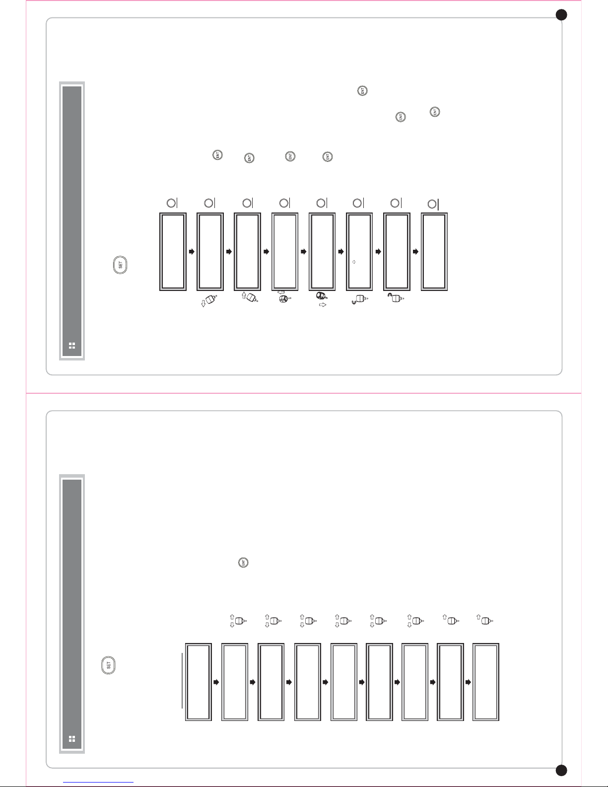
. PTZ SET UP…………………………………………………………
. JOYSTICK CALIBRATION ……………………………………………
. BASIC FUNCTION SETTING AND CONTROL…………………………
1.Preset
2.Tour
3.Pattern
4.Scan
5.Auto Pan
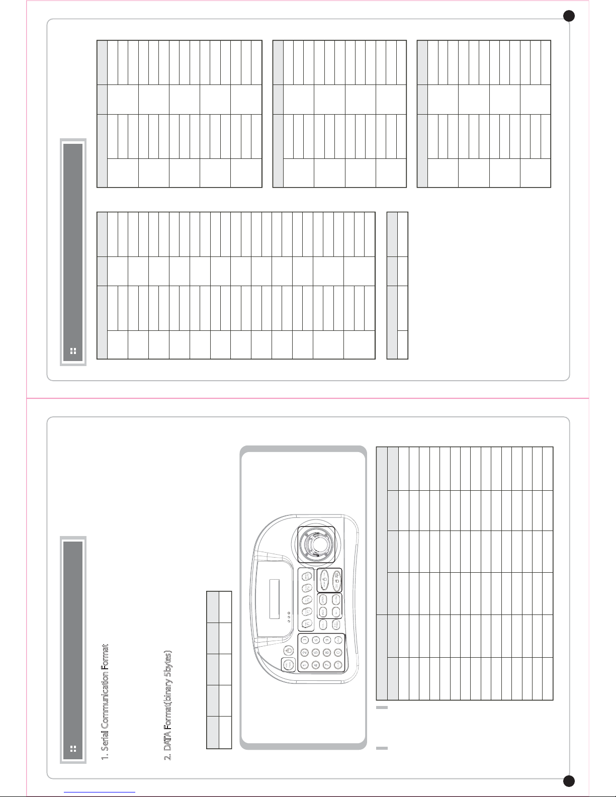
. WTX-1200A PROTOCOL …………………………………………
. SPECIFICATION ……………………………………………………
. DRAWING…………………………………………………………
3p
4p
5p
6p
7p
8p
9p
11p
13p
14p
15p
16p
18p
20p
21p
WARNING
CAUTION
This device is recommended for indoor use only.
- Outdoor/Place exposed to rain or moisture should not be used.
- Drop in water may cause severe damage.
- Do not use in too heavy dust, smoke nor humid environments.
- The device do not leave too hot or cold.
- Always keep the operating temperature between 0'c and 45'c.
- Do not put this unit in direct sunlight.
- (It causes discolor or damage. )
- Do not give this unit a severe shock.
- Unplug the power when thunder, lightning storm.
(May cause fire or damage.)
MAINTENANCE
- When controller body dirt, turn o the power and wipe the surface with a soft cloth.
- Alcohol, benzene and other chemicals to prevent contact. (The surface is changeable)

04 INTEGRATED CONTROLLER HKB-200
05 INTEGRATED CONTROLLER HKB-200
EGNAHCYRETTABDNASTNETNOCSERUTAEFDNASNOITCNUFNIAM
1. Products
2. Battery change
User Manaual Communication connector
HKB-200
(Controller)
DC12V
Adaptor(optional)
USB cable
DC9V Battery (Purchased separately)
Battery cover
WTX-1200A
This product is system integrated controller which can control up to 255 units such as speed dome,
DVR, multiplexer, receiver…etc.
Excellent system compatibility with a variety of protocol implementations.
An array of buttons, user convenience easy connection with other products and ne control make this
unit as market needful product. This CCTV dedicated controller is very convenient to use by anyone.
• Elegant and ergonomic design
• One unit can control up to 255 pan/tilt cameras and other equipments.
• Long distance remote control is possible through RS-485/422 communication.
• Low power consumption design (20mA.LED off)
• Joystick pan/tilt speed controlling is possible.
• Menu control, company logo input are possible by adopting LCD window.
• Easy to control preset, tour, scan, pattern by using function key.
• The administrator's password can be set.
• Easy connection with DVR and other devices(Interface).
(Protocol modifications are required)
• Mobile using is possible by using inner 9V battery.
• S/W Update port(Protocol update).
• USB Mouse function(DVR control)
• Easy to set-ended by built in signal splitter function.(3ch.Max)
1. Summary
2. Features
3. Controller button overview

06 INTEGRATED CONTROLLER HKB-200
07 INTEGRATED CONTROLLER HKB-200
HARDWARE OVERVIEW PART NAME & FUNCTION
PTZ’s up, down, left ,right position control and MENU settings.
Power input (DC 12V, 140mA)
USB connecting terminal
Use Tx1,2 or 3 for RS-485 /RS-422 connection
Program update port
DC9V battery part
FunctionNo.
Enter the numbers or Set up camera ID/PTZ.
Power on and clear the entered value, or Pre-move is used.
Mouse function ON/OFF button
Shows the number entered, system state and running features.
F1~ MENU/AUTO : Control various functions(preset, tour, pattern, scan, auto)
of controlled devices.
MENU : Adjust PTZ menu.
HOLD : : System features pause.
SHIFT/TURBO : When you press the joystick and button at the same time,
the camera helps you to make quick moves.
Optional (special functions, custom functions) functions are
used in.
AUX : External inputs are used in.
SET : : Adjust camera(pan/tilt)’s menu.
OPEN: IRIS open, CLOSE : IRIS close
Adjust Zoom camera’s focus.(Manual mode).
Activate Zoom camera’s Wide/Tele function.
NO. Button Function
2
1
3
4
5
6
7
8
9
4. Program Update Port
3. RS-485 / RS-422
2. USB Port
1. DC12V Input
5. DC9V Battery
4. PTZ Function Keys
6. Joystick
5. LCD Display
3. Numbers
2. ESC/POWER
1. MOUSE
7. Controller Function Keys
9. Camera Zoom Control
MOUSE
8. Camera Focus Control
DC9V Battery
Program Update Port
RS-485 / RS-422
Push a mouse button for 2~3 seconds
Push a mouse button shortly.
Mouse character description will be displayed
= Left button of Computer mouse
=Right button of Computer mouse
=Scroll key of Computer mouse (Middle Key)
(Simultaneously near far key poush and joystick move)
Mouse Function
Mouse Function
To use mouse function, USB driver should be installed in advance.
No.
Discription
Reference Key
button
4
5
DVR Connection
method
Discription [WDS PEL-D 2.4K]
ID:001
[DVR WKEY 2.4K]
ID:001

INTEGRATED Controller WTX-1200A Keyboard
can be used to connect&control DVR, MULTIPLEXER and other external devices.
RS-485/422 Connection
External device’s RS-485/422 port is connected to this Keyboard’s RS-485/422 terminal block.
When RS-485/422 connection, be careful +, - polarity not be changed.
And check device’s RS-485/422 support is available or not.
DVR Connection
Connect USB cable of this equipment to DVR.
Press the top of the controller’s button.
If you briey press : Camera control mode is switched on the keyboard.
If you press and hold : Mouse function is activated through USB Port.
If you briey press, displays are as follows:.
Transfer speed is 9600bps, Control ID is 001.
Display ID is DVR ID.
If you want to control other ID DVR, push number key and ENT then ID will be changed.
(EX. No.3 button + press for 3 seconds)
* Constant value for each button, for each communication (COMMAND) has been set.
WTX-1200A and DVR mouse function use.
Press and hold the mouse button to start the feature.
Mouse function will start as phrase(MOUSE) ashing on the screen.
1.DVR must be PC compatible.(Device driver required)
2.DVR Power ON
3.WTX-1200A Power ON
4.Mouse speed setting in the main setup (WTX-1200A 2 + )
5.WTX-1200A and DVR connected.
6. If you press and hold button, you can see phrase(MOUSE) ashing on the screen.
7. Check the mouse pointer on the screen.
8. Mouse function used as joystick control.
USE ‘L’, ‘R’ button of mouse
CONNECTION SYSTEM CONFIGURATION
09 INTEGRATED CONTROLLER HKB-200
08 INTEGRATED CONTROLLER HKB-200
DVR WKRY 9.6
ID : 001
DVR WKRY 9.6
ID : 001 MOUSE
DVR PORT
Rx-Rx+ Rx -Rx +
Tx-Tx+
Tx1+ Tx1- Tx2+ Tx2- Tx3+ Tx3- Trx+ Trx-
ENT
Single system conguration (Camera 1, kyeboard 1, DVR 1)
DVR PORT PTZ
PTZ
Rx-Rx+ Rx -Rx +
Tx-Tx+
Tx1+ Tx1- Tx2+ Tx2- Tx3+ Tx3- Trx+ Trx-
Use mouse-pointer moving

10 INTEGRATED CONTROLLER HKB-200
SYSTEM CONFIGURATION PTZ CONTROL
11 INTEGRATED CONTROLLER HKB-200
[WDS PEL-D 2.4K]
ID : 001
Multi system conguration
Multi Port
Multi Port
Max16
CAMERA
Max16
DVR
Rx -Rx +
Rx-Rx+Tx-Tx+ Rx-Rx+Tx-Tx+
Tx1+ Tx1- Tx2+ Tx2- Tx3+ Tx3- Trx+ Trx-
Tx+ Tx- Tx+ Tx- Tx+ Tx- Tx+ Tx-
Rx -Rx +
Single system conguartion (PTZ connected directly)
Multi Port Multi Port
Multi Port
Max16
CAMERA
Max16
DVR
[WDS PEL-D 2.4K]
ID : 001
1.Power On
This device has two types of power use.
1)Connect provided adaptor to power.
2)Insert 9V batteries inside.(Do not connect adaptor.)
3)Power on external devices which are connected to this device
before power on of this device.
4)Turn on the power by pressing button.
5) will be displayed on the screen.
[WDS PEL-D 2.4K]
ID : 001
2. Start page displayed
-1. ID: Shows the ID of the currently selected camera.
-2. Shows the currently selected protocol.
ENT
3.Camera ID Set up
-1. Input wanted number button in the number pad.
-2. Press button then Camera ID will be set up as your selected number.
* 1-255 numbers are selectable. When the number outside the range of inputs selected, last selected
numbers will be treated as the rst digit.

Instructions and Setting up the MAIN SETUP
Connect thepower adapter intotheback of the keyboard and pressing button, The following
display appears on theLCD screen.
Main MENU Set up
If you press button 2 + for 2~3 seconds, you can enter intothe MAIN SETUP.
Input password ( Factory set : 0000)
Show software version and date
(DVR Conummunication speed setting)
(Conmmunication setting)
CONTROLLER CONTROL/SETUP CONTROLLER CONTROL/SETUP
12 INTEGRATED CONTROLLER HKB-200
13
MAIN SETUP
[ MAIN SETUP ]
PASSWORD [ **** ]
[ MAIN SETUP ]
1. VER : *.**
[ MAIN SETUP ]
2. DATE : 20
******
[ MAIN SETUP ]
3. TITLE SET : ABC
[ TITLE SET ]
WONWOO
[ MAIN SETUP ]
4. CONTROL ID : NO.
[ MAIN SETUP ]
5. DVR SPD : 9.6K
[ MAIN SETUP ]
6. COMM : RS422
[ MAIN SETUP ]
8. SLEEP : OFF : OFF/ 1Min/ 5MIn /10Min / 30Min /1 (Hour)
: RS422 / RS485
: 2.4 KBPS~57.6 KBPS
: ID No. Change
: Character Select
: Cursor move
ENT
Select BUZZER ON/ OFF
BACKLIGHT setting for LCD
- Auto :Automatically OFF after 30sec
- ON
- OFF
[ MAIN SETUP ]
9. BUZZER : ON
[ MAIN SETUP ]
7. BACKLIGHT : AUTO
: OFF / ON
Select TERMINATION ON/ OFF
Select joystick speed from 50MS~300MS
: OFF / ON
: OFF / ON / AUTO
[ MAIN SETUP ]
10. TERMINATE: ON
[ MAIN SETUP ]
11. JOYSTICK SPD
[ MAIN SETUP ]
12. MOUSE SPD : HIG
[ MAIN SETUP ]
13.PASSWORD: ****
: HIG / MID / LOW
[ MAIN SETUP ]
14. FACTORY SET
[ MAIN SETUP ]
15. SAVE/EXIT
[ FACTORY SET ]
<NO> YES
[ SAVE / EXIT ]
<NO> YES
Tilte setting when power on
Setting to save power in the standbymode
Mouse speed setting when operated with DVR
Password change (Factory set: 0000)
ENT
Factory set.
All data will be changed tothe factory set.
(Move to YES and press )
Select save thedata or not for the changed
setting value
After factory set, the Tx LED on the LCD screen ashing is
not a malfunction.
After factory set, the joystick must reset the settings in the
Joystick Calibration mode.
ALL DATA
INITIALIZED
JOYSTICK
CALIBRATION

It is for the keyboard to set the Max.movement of joystick
PTZ SETUP JOYSTICK CALIBRATION
14 INTEGRATED CONTROLLER HKB-200
PTZ SETUP
If you press button 1 + for 2~3 seconds, you can enter intothe PTZ SETUP menu.
If you press button 3 + for 2~3 seconds, you can enter intothe
JOYSTICK CALIBRATION menu.
: Input password (Factory set:0000)
:
(1~255) +
: Set theprotocol
: Set thebaudrate(2.4KBPS - 57.6KBPS)
: Set teh PARITY (NONE/EVEN/ODD)
: Save the data
: Exit PTZ SETUP menu
: Set the camera speed
Slow PTZ => PROP: ON
Speed PTZ =>PROP: OFF
PTZ SETUP
[ PTZ SETUP 1 ]
PASSWORD [ **** ]
[ PTZ SETUP 1 ]
1. ADDRESS : 001
[ PTZ SETUP 1 ]
2. MODEL : PEL
[ PTZ SETUP 1 ]
3. PROTOCOL : PEL-D
[ PTZ SETUP 1 ]
4. BAUDRATE : 2.4 K
[ PTZ SETUP 1 ]
5. PARITY : NONE
[ PTZ SETUP 1 ]
6. PROP. : ON
[ PTZ SETUP 1 ]
7. SAVE
[ PTZ SETUP 1 ]
8. EXIT
[ JOYSTICK SAVE ]
<NO> YES
**
***
***
***
***
***
***
[ JOYSTICK CALI. ]
[ JOYSTICK CALI. ]
Show thejosytick center value.
ENT
ENT
ENT
ENT
ENT
ENT
ENT
(CW)
(CCW)
ENT
1. PTZ OFFSET :
2. PAN LEFT :
[ JOYSTICK CALI. ]
3. PAN RIGHT :
[ JOYSTICK CALI. ]
4. TILT UP :
[ JOYSTICK CALI. ]
5. TILT DOWN :
[ JOYSTICK CALI. ]
6. ZOOM WIDE :
[ JOYSTICK CALI. ]
7. ZOOM TELE :
Input camera address byusing joystick
Find the camera which user want to control by using josytick
Move thejoystick tothemaximum amount of left side
and press button
Move thejoystick tothemaximum amount of right side
and press button
Move thejoystick tothemaximum amount of upside
and press button
Move thejoystick tothemaximum amount of downside
and press button
Trun thejoystick head tothemaximum amount of
counterclockwise(zoom) and press button
Trun thejoystick head tothemaximum amount of
clockwise(tele) and press button
Select YES or NO and press button
15 INTEGRATED CONTROLLER HKB-200

16 INTEGRATED CONTROLLER HKB-200
17 INTEGRATED CONTROLLER HKB-200
1. PRESET
User can set the camera position where user want to see.
2. TOUR
When Tour function runs, camera moves from thepreset assigned as the1st
point to the preset
assigned as the last point in sequence. The camera will stay to the each
point for the time set to the
dwell time in Tour Edit and move to the next point.
TOUR
F2
TOUR
F2
TOUR
F2
1
+
1+PSET 3+PSET
2+PSET
PSET
F1 PSET
F1
PSET
F1
1
+
1+PSET 3+PSET
2+PSET
4. SCAN
Camera moves between 2 positions ifthere isno PTZ command
after passing the assigned Dwell time.
5. AUTO PAN
Camera moves twopreset pan positions repeatly.
BASIC FUNCTION SETTING AND CONTROL
SCAN
F4 SCAN
F4
SCAN
F4
1
MENU
AUTO
+
3. PATTERN
Camera memorizes thepath (mostly curve path) by joystick of
controller for assigned time and
revives the path exactly as it memorized.
PATT
F3
PATT
F3
PATT
F3
1
+
ApointB point
90
270
PRESET setting : PRESET NO. + 3sec
PRESET operating : PRESET NO. + 1sec
PATTERN setting : PATTERN NO. + 3sec
PATTERN operating : PATTERN NO. + 1sec
SCAN setting : SCAN NO. + 3sec
SCAN operating : SCAN NO. + 1sec
TOUR setting : TOUR NO. + 3sec
TOUR operating : TOUR NO. + 1sec
Consecutively operating

18 INTEGRATED CONTROLLER HKB-200
19 INTEGRATED CONTROLLER HKB-200
WTX-1200A PROTOCOL
CMD ATAD1
1
2
3
4
5
6
7
8
9
0
ENT
CLR
0x20
0x21
short
shitf + short
short
shitf + short
short
shitf + short
short
shitf + short
short
shitf + short
short
shitf + short
short
shitf + short
short
shitf + short
short
shitf + short
short
shitf + short
short
long
shift + short
short
long
shift + short
0x01
0x03
0x01
0x03
0x01
0x03
0x01
0x03
0x01
0x03
0x01
0x03
0x01
0x03
0x01
0x03
0x01
0x03
0x01
0x03
0x01
0x02
0x03
0x01
0x02
0x03
0x01
0x02
0x03
0x04
0x05
0x06
0x07
0x08
0x09
0x0A
CMD ATAD2
shortESC 0x2A 0x01
CMD DATA
F1
F2
F3
F4
AUTO
short
long
shift + short
short
long
shift + short
short
long
shift + short
short
long
shift + short
short
long
shift + short
0x01
0x02
0x03
0x01
0x02
0x03
0x01
0x02
0x03
0x01
0x02
0x03
0x01
0x02
0x03
0x11
0x12
0x13
0x14
0x15
CMD DATA
NEAR
FAR
TELE
WIDE
short
long
shift + short
short
long
shift + short
short
long
shift + short
short
long
shift + short
0x01
0x02
0x03
0x01
0x02
0x03
0x01
0x02
0x03
0x01
0x02
0x03
0x25
0x26
0x27
0x28
CMD
3
5
ATAD4
AUX
OPEN
CLOSE
SET
short
long
shift + short
short
long
shift + short
short
long
shift + short
short
long
shift + short
0x01
0x02
0x03
0x01
0x02
0x03
0x01
0x02
0x03
0x01
0x02
0x03
0x22
0x23
0x24
0x29
WTX-1200A PROTOCOL
1. Serial Communication Format
Data Communication : RS485 / RS-422
Data bit : 8bit
Stop bit : 1bit
Parity bit : None
Transmission speed : 2400, 4800, 9600, 19200, 38400, 57600 bps
2. DATA Format(binary 5bytes)
STX : 0xA0
ETX : 0xAF
ADDR : 0x01 ~ 0xFF(Address Change : addr value + ENT + long)
**n = don’t care
Joystick
byte 1 byte 2 byte 3 byte 4 byte 5
STX ADDR CMD DATA ETX
Value
0x87
0x86
0x85
0x84
0x83
0x82
0x81
0x80
0x88
0x89
0x8A
0x8B
0x8C
0x8D
0x8F
Action
Wide
Stop
Tele
Action
Left
Stop
Right
Action
Up
Stop
Down
Value
0x7n
0x6n
0x5n
0x4n
0x3n
0x2n
0x1n
0x0n
0x9n
0xAn
0xBn
0xCn
0xDn
0xEn
0xFn
Value
0xn7
0xn6
0xn5
0xn4
0xn3
0xn2
0xn1
0xn0
0xn9
0xnA
0xnB
0xnC
0xnD
0xnE
0xnF
DATACMD
Joystick
1
2
3
45

20 INTEGRATED CONTROLLER HKB-200
21 INTEGRATED CONTROLLER HKB-200
SPECIFICATION
Keyboard
communication
Connector Type Data
Joystick
power
Power consumtion
LCD Display
Operating Temp./ Humidity
Keyboard button
Size, Weight
TERMINAL BLOCK(8p)
Rubber button
Numberic keypad and camera function key
Stick 3-axis, variable speed with zoom
12V DC or
9V battery (batter mode)
Max.140mA
Graphic display 16 character x2 lines
0℃~ 45 ℃/ 10% ~ 70% Non-condensing
280(W) x 180(D) x 100(H) / Net : 0.74kg, Gross : 1.28kg
Pan/Tilt interface : RS-485/422
Interface : RS-485/422
Pan/Tilt operating distance : 4700FT (1029m) on 24 AWG wire
Protocol : Multiple (Pelco-D, Pelco-P, WONWOO, Etc.) (Baud rate selectable)
MODEL HKB-200
DRAWING
100mm
180mm
280mm
** The design and speicication are subject to improvement changes without prior notice.
Popular Control Panel manuals by other brands

Woodward
Woodward easYview Series Technical manual

Schaudt
Schaudt LT 100 operating instructions

IntelliSense
IntelliSense ST900C User manual addendum

Helios
Helios KWL-FB Installation and operating instructions

jablotron
jablotron HESTIA-915 installation manual

Mircom
Mircom FR-320 Series Installation and operation manual

Topcon Positioning Group
Topcon Positioning Group RDS TECHNOLOGY ISOCAN APOLLO ATHENE quick start guide

Benninca
Benninca CP.J4 ESA user manual

Controls
Controls MVP-G142 product manual

weintek
weintek MT-8000 Series installation instructions

SOMFY
SOMFY animeo Solo Series installation guide

Danfoss
Danfoss VLT LCP 21 installation guide