manuals.online logo
Brands
  1. Home
  2. •
  3. Brands
  4. •
  5. Hunter
  6. •
  7. Accessories
  8. •
  9. Hunter MINI-CLIK Parts list manual

Hunter MINI-CLIK Parts list manual

MINI-CLIK
®
RAIN SENSOR
INSTALLATION CARD
Introduction
In most installations, the Mini-Clik acts as a switch that breaks the circuit to
an irrigation system's solenoid valves in response to rain. This allows the
timer to advance as scheduled, but keeps the valves from opening the
water ow. Once the Mini-Clik has dried suciently, the switch closes again
to allow normal operation.
The Mini-Clik has 25' (8 m) of cable attached to it. The cable terminates
with blue leads. These leads will be wired to the SEN terminals or SEN and
SEN COM terminals of the controller. The order in which they are wired
does not matter (Figure 1).
For the conduit model, Mini-Clik-C: This rain sensor unit is the same as the
standard model, except there is no aluminum mounting bracket and a ⁄"
threaded cap that allows for electrical conduit to totally enclose the wires
has been added. Unless local code states otherwise, plumbing-grade PVC
pipe can be used, as well as electrical-grade conduit.
Mounting
Standard Model
Using the screws provided, mount the
Mini-Clik on any surface where it will be
exposed to unobstructed rainfall, but not in
the path of sprinkler spray. The switch-housing
portion must be upright (Figure 2), but the
swivel bracket can be moved for mounting on
any angled surface. Loosen the locknut and
screw before swiveling the bracket, and then
re-tighten.
For model Mini-Clik-C: The conduit acts as the
mounting support for the unit. Therefore, place
and mount the conduit to allow for the desired
sensor location as described in the main
instructions for the standard model. Be sure to
support the conduit suciently along its various lengths.
Helpful Hints for Mounting
A. When looking for a suitable location (such as on the side of a building
or post), the closer the Mini-Clik is to the controller, the shorter the
wire run will be. This will minimize the chance for wire breaks.
B. The ideal location for mounting is not always the most practical
location. In the case where a compromise must exist (such as a low
location on a side wall rather than a preferred higher location), note
that the Mini-Clik will still work because it will always receive some
rainfall — it just will not be as accurate in its gauging as it could be.
C. As described in the “Operation” section of this manual, “reset
rate” refers to the amount of time it takes the Mini-Clik to dry
out suciently for the sprinkler system to be allowed to come
back on. The mounting location will aect this rate and must
be taken into consideration should extreme conditions exist.
For example, mounting the Mini-Clik on a very sunny, southern end
of a building may cause the Mini-Clik to dry out sooner than desired.
Similarly, mounting on the northern end of a building with constant
shade may keep the Mini-Clik from drying soon enough.
Once the Mini-Clik is mounted, run the wire to the controller. Fasten it
every few feet with wire clips or staples for best results. If an extension
to the wire provided is needed, use the following table to determine the
minimum wire gauge needed:
If the extension needed is:
use:
Wiring to Your Irrigation System
IMPORTANT: The standard model Mini-Clik is sold and designed for
hooking up to 24-volt irrigation controllers only. For wiring to 110- or
220-volt irrigation controllers, consult your distributor or the
factory. All wiring must conform to National Electrical Code or
applicable local codes.
For model Mini-Clik-C: WARNING! This unit is designed to be installed
in conjunction with 24 VAC circuits only. Do not use with 110 or 220 VAC
circuits.
Other Controllers
The two most common situations are shown below. For non-standard
wiring situations, consult your distributor or request our non-standard
wiring information packet.
X-CORE®PRO-C®
HCC
HC
PRO-HC
ACC2
Figure 1
Figure 2
ACCI-CORE®
24VAC
SEN
REM
C
24 VAC
24 VAC
GND
SEN-1
SEN COM
SEN-2
S1 S1
S2
S2
C
C
GND
AC1
AC2
REM
C
P/MV
SEN
SEN
AC2
AC1
GND
+
–
+
–
+
–
+
–
24
SEN1
SEN1
SEN2
SEN2
SEN3
SEN3
SEN4
SEN4
VAC
COM
TEST
SEN
SEN
REM
24VAC
24VAC
GND
ICC2
24V
24V
SENSOR 1
SENSOR 2
COMMON
SEN C
SEN 2
SEN 1
REM
24VAC
24VAC
GND
24VAC
COM
P/MV3
COM
+ SEN1 SEN1 –
+ SEN2
SEN2 –
+ SEN3
SEN3 –
0–100' (15–30 m)
18 AWG (1 mm)
>100' (>30 m)
16 AWG (1.3 mm)
 LIT- Rev D /
© 2018 Hunter Industries Incorporated | www.hunterindustries.com
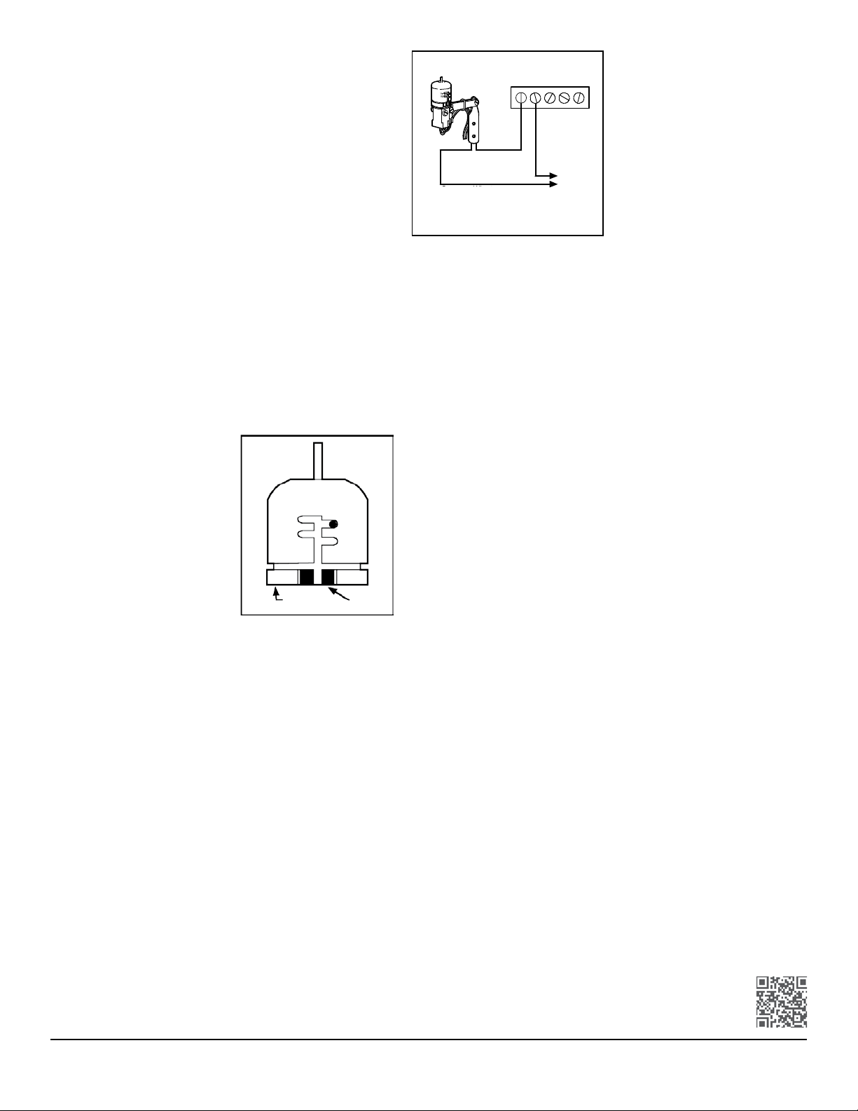
24-Volt Solenoid Valves Only (No Booster Pump) — Figure 3
With the two wires from the Mini-Clik at the controller, locate the
“common ground” wire of the solenoid valves. If it is connected to
the common terminal on the controller, disconnect it. Attach one wire
of the Mini-Clik to the “common” terminal (usually marked “C”) on the
controller. Attach the other wire of the Mini-Clik to the common wire
leading to the valves. Note: The common wire to the valves does not
have to be interrupted at the controller. The Mini-Clik can be wired
anywhere along the common wire line (an example would be at the
valve box location).
Operation Check to Verify Correct Wiring
Turn on one zone of the irrigation system that is visible while you are
in reach of the Mini-Clik. Manually depress the spindle at the top of
the Mini-Clik until you hear the switch “click” o. The sprinkler zone
should stop instantaneously. If it does not, check wiring for correct-
ness. It is not necessary to “wet” test the Mini-Clik, although it will
test the operation accurately, if desired.
Adjustments and Operation
The Mini-Clik can keep the
irrigation system from starting or
continuing aer rainfall quantities
of ⁄", ⁄", ⁄", and ⁄". To adjust it
to the desired shut-o quantity,
rotate the cap on the switch
housing so that the pins are located
in the proper slots (Figure 4). Do
not forcibly twist the cap, as this
could break the pins. The time
that it takes the Mini-Clik to reset
for normal sprinkler operation aer
the rain has stopped is determined
by weather conditions (e.g., wind,
sunlight, humidity). These conditions will determine how fast the hygro-
scopic discs dry out. Since the turf is also experiencing the same condi-
tions, their respective drying rates will roughly parallel each other. This
means when the turf needs more water, the Mini-Clik is already reset to
allow the sprinkler system to go at the next scheduled cycle. There is an
adjustment capability on the Mini-Clik that will slow down the reset
rate. By turning the “vent ring” (Figure 4) to completely or partially
cover the ventilation holes, the hygroscopic discs will dry more slowly.
This adjustment can compensate for an “overly sunny” installation
location, or peculiar soil conditions. Experience will best determine
the ideal vent setting.
1⁄8
1⁄2
1⁄4
3⁄4
Vent Ring Vent
Bypassing the Sensor
On Hunter controllers, move the rain sensor switch to “Bypass.” Note: Using
the “manual” switch on non-Hunter controllers typically will not bypass
the sensor.
Maintenance
There is no required maintenance for the unit. The Mini-Clik does not have to
be removed or covered for winterizing purposes.
Troubleshooting
Follow these simple checks rst before assuming the unit is bad and replacing it.
If the system will not come on at all:
A. First, check to see that the Mini-Clik discs are dry and the switch “clicks”
on and o freely by pressing the top of the spindle.
B. Next, look for breaks in the wire leading to the Mini-Clik and check
all wire connections.
C. Finally, if the Mini-Clik is dry and the wire leading to it is good, check the
Mini-Clik switch by nicking the insulation of the two “outer” wires near the
unit to expose copper. Turn one sprinkler zone on, and apply a “jumper
wire” across the two exposed wires. If the sprinkler now comes on, the
switch is bad. Wrap all nicked wires with electrical tape.
If the System Will Not Shut O Even Aer Heavy Rainfall
A. Check wiring for correctness (see “Operation Check to Verify Correct Wiring”).
B. Check the sensitivity setting (move the cap to a more sensitive setting).
The Mini-Clik is an accurate rain gauge and can be veried by setting up a
tube-type rain gauge in the same vicinity and making periodic readings.
C. Is the rainfall actually hitting the Mini-Clik? Check for obstructions to
rainfall (e.g., overhangs, trees, or walls).
Need help? Visit hunter.direct/miniclikhelp
All Mini-Clik models are listed by Underwriters Laboratories Inc. (UL). Samples of these
devices have been evaluated by UL and meet the applicable UL standards for safety.
1234
Mini-Clik Controller
C
Figure 3
Solenoid
Valves
Common Wire to
All Valves
Figure 4
Figure 3
Mini-Clik Controller
Common Wire to
All Valves
Valves
Solenoid

Other manuals for MINI-CLIK

1

Other Hunter Accessories manuals

Hunter Wireless Rain-Clik User manual

Hunter

Hunter Wireless Rain-Clik User manual

Hunter BP-01 User manual

Hunter

Hunter BP-01 User manual

Hunter Solar Sync User manual

Hunter

Hunter Solar Sync User manual

Hunter WRC User manual

Hunter

Hunter WRC User manual

Hunter Wireless Rain-Clik User manual

Hunter

Hunter Wireless Rain-Clik User manual

Hunter WFS Programming manual

Hunter

Hunter WFS Programming manual

Hunter Solar Sync User manual

Hunter

Hunter Solar Sync User manual

Hunter RAIN-CLIK WR-CLIK Operating instructions

Hunter

Hunter RAIN-CLIK WR-CLIK Operating instructions

Hunter LIT-293 User manual

Hunter

Hunter LIT-293 User manual

Hunter Light Kit Instruction manual

Hunter

Hunter Light Kit Instruction manual

Hunter ET SYSTEM SMARTPORT User manual

Hunter

Hunter ET SYSTEM SMARTPORT User manual

Hunter Hunter Accessory Table 20523 User manual

Hunter

Hunter Hunter Accessory Table 20523 User manual

Hunter MINI-CLIK User manual

Hunter

Hunter MINI-CLIK User manual

Hunter FLOW-SYNC HFS Programming manual

Hunter

Hunter FLOW-SYNC HFS Programming manual

Hunter FLOW-CLIK Operating instructions

Hunter

Hunter FLOW-CLIK Operating instructions

Hunter Wireless Rain-Clik User manual

Hunter

Hunter Wireless Rain-Clik User manual

Hunter 43758 User manual

Hunter

Hunter 43758 User manual

Hunter DSP700 Series User manual

Hunter

Hunter DSP700 Series User manual

Hunter WIRED RAIN-CLIK RAIN-CLIK Parts list manual

Hunter

Hunter WIRED RAIN-CLIK RAIN-CLIK Parts list manual

Hunter RAIN CLIK WR-CLIK Operating instructions

Hunter

Hunter RAIN CLIK WR-CLIK Operating instructions

Hunter Wireless Rain-Clik User manual

Hunter

Hunter Wireless Rain-Clik User manual

Hunter Soil-Clik User manual

Hunter

Hunter Soil-Clik User manual

Hunter Rain-Clik WRC-TR User manual

Hunter

Hunter Rain-Clik WRC-TR User manual

Hunter Wireless Rain-Clik User manual

Hunter

Hunter Wireless Rain-Clik User manual

Popular Accessories manuals by other brands

Philips DoseAware Instructions for use

Philips

Philips DoseAware Instructions for use

Takex PB- 50FA installation manual

Takex

Takex PB- 50FA installation manual

Indexa 1000M owner's manual

Indexa

Indexa 1000M owner's manual

Carpex Micro product manual

Carpex

Carpex Micro product manual

Lantus SoloSTAR How to use

Lantus

Lantus SoloSTAR How to use

Creative 202 owner's manual

Creative

Creative 202 owner's manual

Profroid SOPRANO Series INSTALLATION COMISSIONING OPERATING MAINTENANCE

Profroid

Profroid SOPRANO Series INSTALLATION COMISSIONING OPERATING MAINTENANCE

Cornelius COR9530UBCST Service manual

Cornelius

Cornelius COR9530UBCST Service manual

LightwaveRF JSJS LW380 Operation manuals

LightwaveRF

LightwaveRF JSJS LW380 Operation manuals

Tellur TLL158231 user manual

Tellur

Tellur TLL158231 user manual

Garmin GPSMAP 520 - Marine GPS Receiver instructions

Garmin

Garmin GPSMAP 520 - Marine GPS Receiver instructions

Wiremold 2600-10 Installation instructions manual

Wiremold

Wiremold 2600-10 Installation instructions manual

Vetako Ermak-10 user manual

Vetako

Vetako Ermak-10 user manual

Emos E06016 manual

Emos

Emos E06016 manual

Hugo Müller TS 30.00 mod instruction manual

Hugo Müller

Hugo Müller TS 30.00 mod instruction manual

Monacor DC-160 Mounting instructions

Monacor

Monacor DC-160 Mounting instructions

Philips HF3485/01 quick start guide

Philips

Philips HF3485/01 quick start guide

CASUALPLAY bp105705 instruction manual

CASUALPLAY

CASUALPLAY bp105705 instruction manual

manuals.online logo
manuals.online logoBrands
  • About & Mission
  • Contact us
  • Privacy Policy
  • Terms and Conditions

Copyright 2025 Manuals.Online. All Rights Reserved.