P/N 700881 LIT-358 D 2/18
© 2018 Hunter Industries Incorporated | www.hunterindustries.com
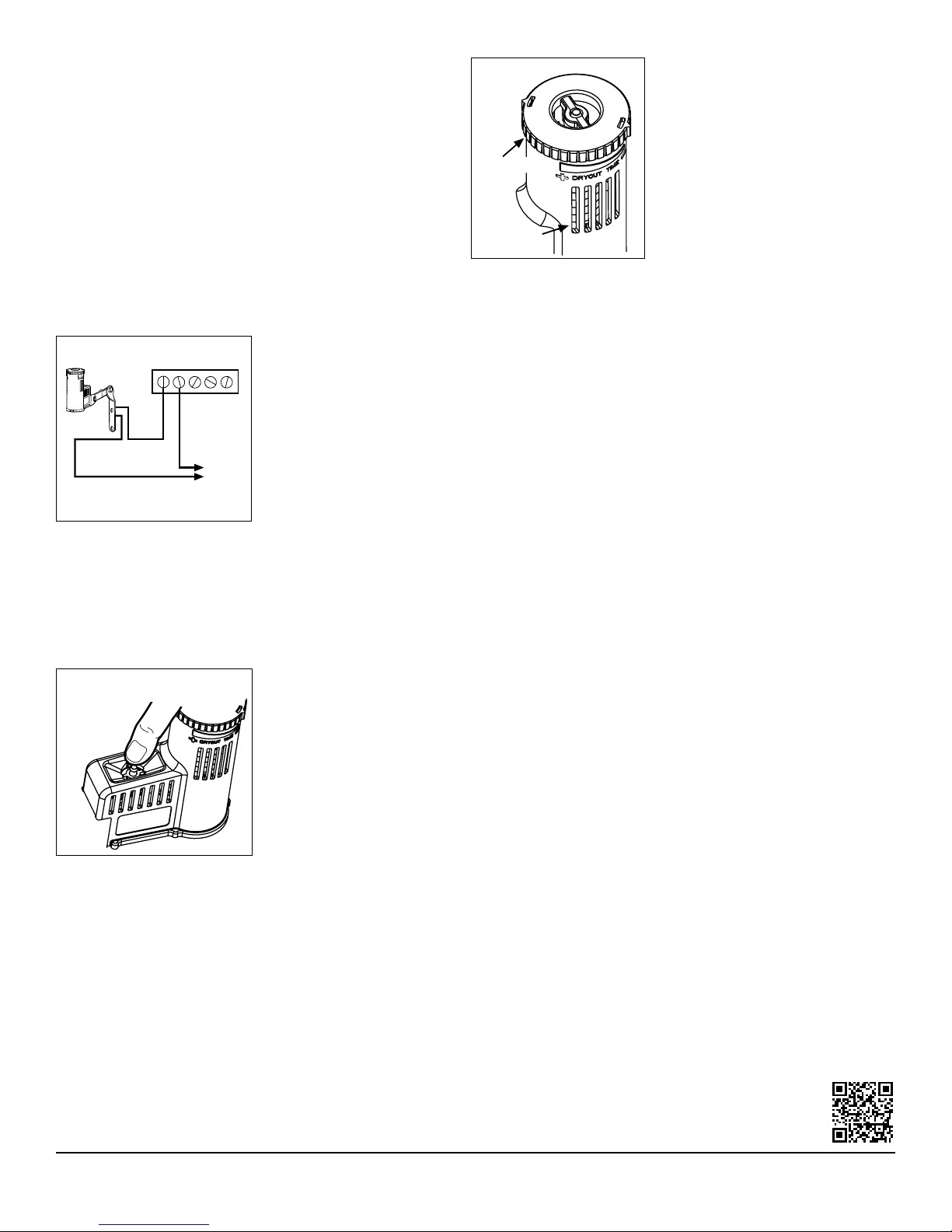
Operation Check to Verify Correct Wiring
Turn on one zone of the irrigation system that is visible while you
are in reach of the Rain-Clik. Manually depress the spindle at the top
of the Rain-Clik until you hear the switch “click” o. The sprinkler
zone should stop instantaneously. If it does not, check wiring for
correctness. It is not necessary to “wet” test the Rain-Clik, although it
will test the operation suciently, if desired (Figure 3).
Adjustments and Operation
The Rain-Clik can keep the irrigation system from starting or continuing
aer rainfall. The time that it takes the Rain-Clik to reset for normal
sprinkler operation aer the rain has stopped is determined by weather
conditions (wind, sunlight, humidity, etc.). These conditions will
determine how fast the hygroscopic discs dry out, and since the turf
is also experiencing the same conditions, their respective drying rates
will roughly parallel each other. So when the turf needs more water, the
Rain-Clik is already reset to allow the sprinkler system to run at the next
scheduled cycle.
There is an adjustment capability on the
Rain-Clik that will slow down the reset
rate. By closing the “vent” (Figure 4) to
completely or partially cover the ventilation
slots, the hygroscopic discs will dry out more
slowly. This adjustment can compensate for
an “overly sunny” installation location, or
peculiar soil conditions. Experience will best
determine the ideal vent setting.
Rain-Clik utilizes single-disc technology
to turn o your sprinkler system within
the first five minutes of rainfall. For light
showers and amounts of rain less than ¹⁄₈" (3 mm), the single disc will shut
o the system for 30 minutes to 4 hours, depending on weather conditions.
Adjusting the vent cap will not have an eect on the dryout time of the single
disc. For heavier rain showers in excess of ¹⁄₈" (3 mm), the disc stack under the
vent cap will hold the system o for an appropriate amount of time. The disc
stack dryout time is what the vent cap adjustment controls.
Bypassing the Sensor
The Hunter X-Core®, Pro-C®, ICC2, and I-Core® controllers are equipped with a
built-in bypass that allows you to override an active sensor. For controllers not
equipped with this feature, should you desire to bypass the operation of the
Rain-Clik for any reason (i.e., turn on your system even though the Rain-Clik
has shut “o” due to rainfall), there is a simple way to do this: add our Bypass
Switch Box. This mounts on or next to the controller, and by simply moving the
switch, the Rain-Clik is bypassed.
Note: Using the “manual” switch on non-Hunter controllers typically will not
bypass the sensor.
Maintenance
There is no required maintenance for the unit. The Mini-Clik does not have to
be removed or covered for “winterizing” purposes.
Troubleshooting
Follow these simple checks rst before assuming the unit is bad and replacing it. If
the system will not come on at all:
A. First, check to see that the Rain-Clik discs are dry and the switch “clicks” on
and o freely by pressing the top of the spindle.
B. Next, look for breaks in the wire leading to the Rain-Clik and check all wire
junctions.
C. Verify temperature is above 37° F (3°C) (for Rain/Freeze-Clik model).
If the System Will Not Shut O Even Aer Heavy Rainfall:
A. Check wiring for correctness (see “Operation Check to Verify Correct Wiring”).
B. Is the rainfall actually hitting the Rain-Clik? Check for obstructions to
rainfall (e.g., overhangs, trees, or walls).
Need help? Visit hunter.direct/rainclikhelp
Wiring to Your Irrigation System (cont.)
Wiring to Other Controllers
The most common situation is shown below.
1. 24-Volt Solenoid Valves Only (Figure 2)
With the two wires from the Rain-Clik at the controller, locate the
“common ground” wire of the solenoid valves. If it is connected to the
common terminal on the controller, disconnect it. Attach one wire of
the Rain-Clik to the “common” terminal (usually marked “C”) on the
controller. Attach the other wire of the Rain-Clik to the common wire
leading to the valves.
Note: The common wire to the valves does not have to be interrupted at
the controller. The Rain-Clik can be wired anywhere along the common
wire line.
Rain/Freeze-Clik
Shade
Figure A
Rain/Freeze-Clik Hunter Controllers
SEN
SEN
C
TEST
P MV
Figure 1
Rain/Freeze-Clik Other Controller
Valves
Common Wire to All Valves
Solenoid
Figure 2
21C 3 4
Figure 3
Manually depress the spindle
at the top of the Rain-Clik
Standard Mount
Rain/Freeze-Clik
Shade
Figure A
Rain/Freeze-Clik Hunter Controllers
SEN
SEN
C
TEST
P MV
Figure 1
Rain/Freeze-Clik Other Controller
Valves
Common Wire to All Valves
Solenoid
Figure 2
21C 3 4
Figure 3
Manually depress the spindle
at the top of the Rain-Clik
Rain/Freeze-Clik
Shade
Figure A
Rain/Freeze-Clik Hunter Controllers
SEN
SEN
C
TEST
P MV
Figure 1
Rain/Freeze-Clik Other Controller
Valves
Common Wire to All Valves
Solenoid
Figure 2
21C 3 4
Figure 3
Manually depress the spindle
at the top of the Rain-Clik
Standard Mount
Manufactured under U.S. Patent Pending
All Rain-Clik models are listed by Underwriters Laboratories, Inc. (UL). Samples of these
devices have been evaluated by UL and meet the applicable UL standards for safety.


